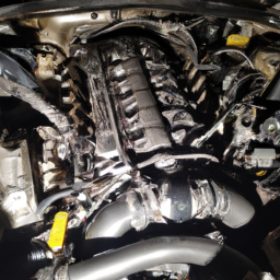
Adjusting the gear ratio on a Cummins B V4 or V6 engine is a complex task that typically involves several mechanical components. click here for more details on the download manual…..
- Diesel class Cummins 12v runaway 12v run away in diesel class.
- 6.7 Cummins number 6 cylinder damage
Below are the steps and tools required for this process, presented in bullet points for clarity:
### Tools Required
– **Torque Wrench**
– Used to apply the correct amount of torque to fasteners, ensuring they are tightened to manufacturer specifications.
– **Socket Set**
– A complete set of sockets will be needed to remove various bolts and nuts. Ensure you have both metric and standard sizes available.
– **Wrenches**
– Adjustable wrenches and combination wrenches will be necessary for loosening and tightening bolts in tight spaces.
– **Pliers**
– Needle-nose pliers are helpful for gripping small parts, while larger pliers can assist with larger clamps or connectors.
– **Screwdrivers**
– Both flathead and Phillips screwdrivers are essential for removing any cover plates or components that are secured with screws.
– **Gear Puller**
– A tool used to remove gears or pulleys from shafts without damaging them. Essential If you need to remove any gear components to change the ratio.
– **Calipers or Micrometer**
– For measuring the dimensions of gears to ensure proper fitment and alignment after adjustments.
– **Dial Indicator**
– Used to measure any backlash in the gear system, ensuring that the gears mesh properly after adjustment.
– **Service Manual**
– A detailed service manual specific to the Cummins B V4 or V6 Engine will provide the necessary torque specifications, diagrams, and procedures for gear ratio adjustments.
### Steps for Gear Ratio Adjustment
– **Preparation**
– Disconnect the battery to prevent any electrical shorts or accidental starts during maintenance.
– Ensure the vehicle is on a flat surface and use wheel chocks for safety.
– **Remove Necessary Covers**
– Use screwdrivers to remove any Engine covers that obstruct access to the gear assembly. This may include timing covers or valve covers.
– **Identify Gear Components**
– Locate the gears involved in the gear ratio. This typically includes the crankshaft gear, camshaft gear, and any other driven gears that affect the overall ratio.
– **Inspect Existing Gear Setup**
– Use the dial indicator to measure the current backlash and ensure that the existing gears are in good condition. Look for wear or damage.
– **Calculate Desired Gear Ratio**
– Determine the desired gear ratio based on your performance goals. This may involve calculations based on your current setup, desired RPMs, and load conditions.
– **Select Replacement Gears**
– Choose gears that match your desired ratio. Ensure these gears are compatible with your existing setup and check specifications against your service manual.
– **Remove Existing Gears**
– Use the gear puller to carefully remove the existing gears from their respective shafts. take care not to damage the shafts during this process.
– **Install New Gears**
– Position the new gears onto the shafts, ensuring they are properly aligned. Use the torque wrench to tighten any fasteners to the specified torque.
– **Check Gear Alignment**
– Re-measure the backlash with the dial indicator. Adjust as necessary to ensure the gears are properly meshed and no excessive play exists.
– **Reassemble Engine Components**
– Replace covers and components that were removed. Ensure all screws and bolts are tightened to the appropriate specifications.
– **Reconnect Battery and Test**
– Reconnect the battery and perform a test run of the engine. Listen for any unusual noises that might indicate improper installation.
– **Final Inspection**
– After the test run, recheck torque on all fasteners and perform a final inspection to ensure everything is secure and functioning correctly.
### Safety and Precautions
– Always wear safety gear, including gloves and goggles, to protect yourself during mechanical work.
– If unsure about any step, consult a professional mechanic or refer to the service manual for guidance.
– dispose of any old oil or parts according to local regulations.
By following these steps and utilizing the required tools, you can effectively adjust the gear ratio on a Cummins B V4 or V6 engine, optimizing its performance for your specific needs.
The license plate light is a crucial automotive component designed to illuminate the rear license plate of a vehicle. This small yet significant light enhances visibility and ensures that the license plate is easily readable in low-light conditions, such as during nighttime or inclement weather. Typically, the license plate light is mounted on or near the rear of the vehicle, often integrated into the trunk lid, bumper, or a dedicated housing.
Functionally, the license plate light serves important legal and safety purposes. Most jurisdictions require that license plates are clearly visible at all times, and a functioning license plate light helps drivers comply with these regulations. Additionally, a well-lit license plate can assist law enforcement in identifying vehicles during nighttime operations, thereby contributing to overall road safety.
The license plate light usually consists of a housing that contains a bulb, which can be an incandescent, halogen, or LED type, depending on the vehicle’s design and the owner’s preferences. LED lights have become increasingly popular due to their energy efficiency, longer lifespan, and brighter illumination compared to traditional bulbs. Maintenance of the license plate light generally involves checking the bulb’s functionality and replacing it when necessary. Overall, while small in size, the license plate light plays a vital role in vehicle safety, compliance, and visibility on the road.
To perform a shift drum repair on a Cummins B V4 or V6 engine, first, remove the engine cover and any necessary components to access the transmission. Disconnect the shift linkage and carefully remove the shift drum. Inspect for wear or damage and replace if needed. Reinstall the new or repaired shift drum, ensuring proper alignment with the shift forks. Reconnect the shift linkage and reassemble any removed components. Finally, check the operation of the shift mechanism before starting the engine to ensure proper functionality. Always refer to the service manual for specific instructions and torque specifications.