Download Daihatsu Charade G100 G102 Chassis 1987-1993 Service Manual –

australia
Replacing the transmission solenoid pack on a Daihatsu Charade G100/G102 chassis involves several steps. click here for more details on the download manual…..


      Fitting Rear Suspension: Charade Restoration #24 After all the underbody cleaning and painting it was a pleasure to refit the tidied up components and get the Charade shell rolling …

    Here’s a reverse order guide to help you understand the process:

    ### 6. Reconnect the Battery
    – **Reconnect the Negative Terminal**: After all components are reassembled, Reconnect the negative battery terminal and ensure it is secure.

    ### 5. Reinstall the Transmission Pan
    – **Position the Pan**: Align the transmission pan back onto the transmission.
    – **Secure with Bolts**: Tighten all the bolts to secure the pan, ensuring a proper seal and avoiding leaks.
    – **Replace Gasket if Necessary**: If the gasket was removed or damaged, replace it before reinstalling the pan.

    ### 4. Reconnect Electrical Connectors
    – **Attach Solenoid Pack Connectors**: Reconnect any electrical connectors that were detached from the solenoid pack.
    – **Check Wiring**: Ensure that all Wiring is in good condition and securely connected to prevent any electrical issues.

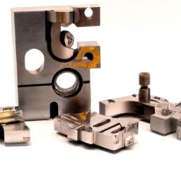
    ### 3. Install the New Solenoid Pack
    – **Position the New Pack**: Place the new transmission solenoid pack into its designated location on the transmission.
    – **Secure with Bolts**: Tighten the bolts that hold the solenoid pack in place, ensuring it is securely fixed.

    ### 2. Drain Transmission Fluid
    – **Drain Fluid**: If not already done, drain the transmission fluid to prevent spillage when removing the solenoid pack and pan. Use a suitable container to catch the fluid.

    ### 1. Remove the Transmission Pan
    – **Unscrew Bolts**: Use a socket wrench to remove the bolts securing the transmission pan to the transmission.
    – **Carefully Detach Pan**: Gently pry the pan away from the transmission, allowing any remaining fluid to drain into your container.

    ### Additional Steps (Before Starting)
    – **Gather Tools and Materials**: Ensure you have the necessary tools (socket set, wrenches, etc.) and a replacement solenoid pack.
    – **Prepare the Vehicle**: Park the Daihatsu Charade on a level surface, engage the parking brake, and raise the vehicle securely with jack stands if necessary.
    – **Consult the Manual**: Refer to the vehicle’s service manual for any model-specific instructions or torque specifications.

    Following these steps in reverse order should help you undersdownload Daihatsu Charade G100 G102 Chassis workshop manualtand the process of replacing the transmission solenoid pack on a Daihatsu Charade G100/G102 chassis. Always take safety precautions and consider consulting a professional if you’re unsure about any steps.
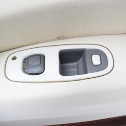
    A window seal is an essential component of a vehicle’s window system, playing a crucial role in maintaining the integrity and functionality of the windows. Typically made from materials such as rubber, silicone, or polyurethane, window seals are designed to provide a watertight and airtight barrier between the vehicle’s body and the glass of the window. This component is located around the perimeter of the window frame, ensuring that water, dust, and wind do not enter the cabin of the vehicle, which helps maintain a comfortable interior environment.

    In addition to their primary function of preventing leaks, window seals also contribute to reducing noise levels inside the vehicle by dampening sound vibrations from the outside. This is particularly important for creating a pleasant driving experience. Furthermore, window seals play a role in the overall structural integrity of the vehicle. They help secure the glass in place, preventing it from rattling or becoming dislodged during driving, especially in the event of an accident.

    Over time, window seals can degrade due to exposure to sunlight, temperature fluctuations, and environmental factors, leading to cracks, tears, or loss of elasticity. Regular inspection and maintenance of window seals are essential to ensure they function effectively, as compromised seals can lead to water leaks, increased wind noise, and even electrical issues if water reaches sensitive components. Replacing worn or damaged window seals is crucial for preserving the vehicle’s comfort, safety, and durability.

    Download Dodge Magnum LX 2005-2006 Workshop Service Repair Manual –

    service
    Performing a shift interlock repair on a Dodge Magnum LX involves several tools and steps. click here for more details on the download manual…..


      How-To #8: Reset Cluster Gauge/Dashboard – 2006-2010 Dodge Charger + Other LX Models Quick tutorial on how to reset your instrument cluster, dash board, or cluster gauge – however you want to call it! If the gauges are …

      SYMPTOMS OF BAD PISTON RINGS In this video, you will learn 5 symptoms of bad piston rings. Watching this video will help you diagnose whether it is time to replace …

    Below is a detailed description of the necessary tools and the process:

    ### Tools Needed

    – **Flathead Screwdriver**:
    – Used to pry off trim pieces and remove clips without damaging surrounding components.

    – **Phillips Screwdriver**:
    – Required for removing screws that secure various panels and components in place.

    – **Socket Set with Ratchet**:
    – Typically, a 10mm socket will be necessary to remove bolts securing components like the center console and the shift assembly.

    – **Torx Bit Set**:
    – Certain screws, especially in the interior, may require Torx bits (like T15) for removal.

    – **Pliers**:
    – Useful for gripping and manipulating small components, especially when disconnecting clips or wires.

    – **Trim Removal Tool**:
    – Helps in safely removing interior trim without scratching or damaging surfaces.

    – **Multimeter**:
    – For testing electrical components and ensuring proper voltage and continuity in the shift interlock system.

    – **Replacement Parts**:
    – Depending on the diagnosis, you might need a new shift interlock solenoid or associated wiring connectors.

    ### Repair Process

    – **Preparation**:
    – Ensure the vehicle is parked on a flat surface and the ignition is turned off. Disconnect the negative battery terminal to prevent electrical shorts.

    – **Remove Interior Trim**:
    – Use the flathead screwdriver or trim removal tool to carefully pry off the trim surrounding the gear shift. Be cautious to avoid breaking clips.

    – **Access the Shift Assembly**:
    – Once the trim is removed, use the Phillips screwdriver and socket set to remove screws and bolts securing the center console. This may involve removing the cup holders or any other components attached to the console.

    – **Disconnect Wiring Harnesses**:
    – Carefully unplug any electrical connectors attached to the shift assembly. Note their arrangement for easy reconnection later.

    – **Inspect the Shift Interlock Mechanism**:
    – Locate the shift interlock solenoid, which is often found near the gear shift lever. Inspect for any visible damage, corrosion, or disconnection.

    – **Test the Solenoid**:
    – Use a multimeter to check the solenoid for continuity. If there’s no continuity, the solenoid likely needs replacement.

    – **Replace Defective Parts**:
    – If the shift interlock solenoid is faulty, remove it by unscrewing it from its mount. Install the new solenoid in reverse order, ensuring it’s securely fastened.

    – **Reassemble the Console**:
    – Once repairs are complete, reattach any disconnected wiring harnesses. Then, reinstall the center console and any trim pieces. Secure everything back in place with screwsdownload Dodge Magnum LX workshop manual and bolts.

    – **Reconnect Battery and Test**:
    – Reconnect the negative battery terminal. Start the vehicle and test the shift interlock function by attempting to shift from park to drive. Ensure the system operates smoothly.

    – **Final Inspection**:
    – Check for any loose parts or rattles and ensure that all components are securely fastened. Clean up your work area and dispose of any old parts responsibly.

    ### Safety Precautions

    – Always wear safety goggles and gloves to protect yourself from sharp edges and electrical components.
    – Make sure the vehicle is in park and the parking brake is engaged before starting the repair.

    This comprehensive guide should help you perform a shift interlock repair on a Dodge Magnum LX effectively. If you encounter any issues or feel uncomfortable at any stage, consult a professional mechanic.
    The high beam switch is a crucial component in a vehicle’s lighting system, primarily responsible for controlling the operation of the high beams, which are the brightest headlights available on most vehicles. Located typically on the steering column or as part of the headlight control stalk, this switch allows drivers to toggle between low and high beam settings, enhancing visibility during nighttime driving or in poorly lit conditions.

    When activated, the high beam lights provide a more intense and focused beam of light, illuminating the road ahead significantly farther than low beams. This can be particularly beneficial on dark, rural roads where street lighting is sparse. However, the use of high beams must be balanced with consideration for other road users, as they can cause glare and reduce visibility for oncoming drivers. Therefore, the high beam switch often includes a mechanism that automatically dims the headlights when it detects oncoming traffic or when the vehicle comes near other vehicles from behind, ensuring safety and compliance with traffic regulations.

    In modern vehicles, the high beam switch may also be integrated with advanced features such as automatic high beams, which utilize sensors to detect surrounding light conditions and adjust the beam settings accordingly. This automation enhances convenience and safety, allowing drivers to maintain optimal visibility without the need for manual switching. In summary, the high beam switch is a vital element for effective vehicle operation, contributing to both safety and driving comfort.

    Download 2008 Mercedes-Benz CLK-Class CLK350 Cabrio (A209) OEM Download Service & Repair Manual Software –

    discount
    Replacing the clutch release bearing in a Mercedes-Benz CLK350 Cabrio (A209) involves several steps and components. click here for more details on the download manual…..


      Crucial Maintenance & upgrade: Mercedes CLK500 W209 First Must do Maintenance & upgrade: CLK500 W209 Sports Brake Package. 5 projects in 2 hours. Rotors, pads, Bleeding and …

      Avoid These Costly Problems – Mercedes CLK – C and E-Class… Avoid These Costly Problems – Mercedes CLK – C-class and E-class…If you have decided to buy a Mercedes CLK, C-class or an …

    This is a detailed guide to help you understand the process, but please note that working on your vehicle can be complex, and if you’re not confident in your mechanical skills, it’s best to consult a professional mechanic.

    ### Required Tools and Equipment
    1. **Basic Hand Tools**:
    – Ratchet and socket set (including extensions)
    – Wrenches (metric sizes)
    – Screwdrivers (flat and Phillips)
    – Pliers
    2. **Special Tools**:
    – Clutch alignment tool (specific to the clutch kit)
    – Torque wrench
    3. **Lifting Equipment**:
    – Car jack and jack stands or a hydraulic lift
    4. **Brake cleaner**: To clean any components during the process
    5. **New Clutch Release Bearing**: Ensure it’s OEM or a quality aftermarket part
    6. **New Clutch Kit (optional but recommended)**: includes the clutch disc, pressure plate, and release bearing
    7. **Gasket Maker/Sealant**: If needed for reassembly

    ### Safety Precautions
    – Always work in a well-ventilated area.
    – Wear safety goggles and gloves.
    – Ensure the vehicle is securely lifted and supported before working underneath it.

    ### Step-by-Step Guide

    #### 1. Preparation
    – **Disconnect the Battery**: Start by disconnecting the negative terminal of the battery to ensure safety.
    – **Lift the Vehicle**: Use a car jack to lift the front of the vehicle and secure it on jack stands.

    #### 2. Remove the Transmission
    1. **Remove the Driveshaft**: Depending on whether your vehicle has a manual or automatic transmission, you may need to remove the driveshaft. This usually involves removing bolts at the differential and sliding the driveshaft out.
    2. **Disconnect Transmission Linkages**: Remove any linkages or cables connected to the transmission.
    3. **Unbolt the Transmission**: Locate the transmission mounting bolts and remove them. These may be located on both the Engine side and the transmission cross-member.
    4. **Support the Transmission**: Use a transmission jack to support the weight of the transmission.
    5. **Remove the Transmission**: Carefully slide the transmission out of the Engine bay. Be cautious of any wires or hoses that may be attached.

    #### 3. Access the Clutch Assembly
    1. **Remove the Clutch Fork**: The clutch fork is usually held in place by a retaining clip or bolt. Remove it to gain access to the release bearing.
    2. **Remove the Pressure Plate and Clutch Disc**: Unbolt the pressure plate from the flywheel. There are usually several bolts that need to be removed in a crisscross pattern to relieve tension evenly. Once unbolted, the pressure plate can be removed, followed by the clutch disc.

    #### 4. Replace the Clutch Release Bearing
    1. **Remove the Old Bearing**: The release bearing is typically mounted on the clutch fork. Slide it off and inspect for any wear or damage.
    2. **Install the New Bearing**: Place the new release bearing onto the clutch fork, ensuring it is seated properly.

    #### 5. Reassemble the Clutch Assembly
    1. **Install the Clutch Disc**: Position the new clutch disc onto the flywheel. Make sure it is aligned properly. You can use a clutch alignment tool to help with this.
    2. **Install the Pressure Plate**: Place the pressure plate over the clutch discdownload Mercedes Benz CLK Class CLK350 Cabrio A209 OEM workshop manual and bolt it back to the flywheel in a crisscross pattern to ensure even clamping force. Refer to your service manual for the specific torque specifications.
    3. **Reinstall the Clutch Fork**: Attach the clutch fork back to its original position.

    #### 6. Reinstall the Transmission
    1. **Position the Transmission**: Carefully slide the transmission back into place, ensuring it aligns with the Engine and input shaft.
    2. **Reattach Transmission Linkages**: Reconnect any linkages or cables that were disconnected.
    3. **Secure the Transmission**: Bolt the transmission back into place securely.
    4. **Reinstall the Driveshaft**: If you removed the driveshaft, reinstall it by sliding it back into place and securing it with bolts.

    #### 7. Final Steps
    1. **Reconnect the Battery**: Once everything is reassembled, reconnect the negative terminal of the battery.
    2. **Test the Clutch**: Before taking the car for a drive, test the clutch operation by pressing the pedal and ensuring it feels normal.
    3. **Check for Leaks**: After starting the vehicle, check for any fluid leaks underneath.

    ### Conclusion
    Replacing the clutch release bearing on a Mercedes-Benz CLK350 Cabrio is a labor-intensive process that requires a good understanding of vehicle mechanics. Always consult the service manual specific to your vehicle for torque specifications and additional details. If you’re unsure at any point, it’s wise to seek the help of a professional mechanic to avoid any potential damage to your vehicle.
    A strut mount is a crucial component of a vehicle’s suspension system, serving as a connection point between the vehicle’s body and its strut assembly. The strut itself is an integral part of the suspension system, providing support, stability, and handling characteristics while absorbing shocks from road imperfections. The strut mount plays a vital role in this system by anchoring the strut to the vehicle’s chassis, ensuring that the strut can effectively manage the forces generated during driving.

    Typically located at the top of the strut, the strut mount is designed to accommodate vertical and lateral loads, allowing for smooth movement of the strut during compression and rebound. It often features a rubber or polyurethane bushing that acts as a damping material, helping to isolate vibrations and noise from the road, which contributes to a more comfortable ride for passengers. Additionally, the strut mount may include a bearing that allows for the rotation of the strut during steering, enhancing the vehicle’s maneuverability.

    Over time, strut mounts can wear out due to exposure to road conditions, corrosion, and the stresses of driving. Symptoms of a failing strut mount include clunking noises, uneven tire wear, and poor handling. Regular inspection and timely replacement of strut mounts are essential for maintaining the overall performance and safety of the vehicle’s suspension system.

    Download 2008 Mercedes-Benz S-Class S420 (W221) OEM Download Service & Repair Manual Software –

    books
    Replacing the gearbox synchronizer in a Mercedes-Benz S-Class S420 W221 is a complex procedure that typically requires mechanical experience, specialized tools, and a good understanding of automotive systems. click here for more details on the download manual…..


      Check Coolant Level on Mercedes #mercedes #cclass #eclass #sclass #ml #shorts #viral #fyp #coola…

      Fix your Mercedes ABC – don’t do coilovers. Premium Mercedes S and SL models have the most advanced factory suspension ever offered called ABC (Active Body Control).

    However, I can break it down into simpler terms for better understanding. Please note that if you’re not comfortable with such procedures, it’s always best to consult a professional mechanic. Here’s a simplified guide on what the process generally involves:

    ### Tools and Materials Needed:
    1. **Basic hand Tools**: Wrenches, sockets, screwdrivers, etc.
    2. **Gearbox Oil**: To refill the gearbox after replacement.
    3. **Replacement Synchronizer**: Make sure it’s the correct part for the S420 W221.
    4. **Torque Wrench**: For properly tightening bolts.
    5. **Shop Manual**: For specific torque settings and step-by-step guidance.

    ### Steps to Replace the Gearbox Synchronizer:

    1. **Safety First**:
    – Ensure the car is parked on a flat surface.
    – Disconnect the battery to prevent any electrical issues.
    – Use wheel chocks to prevent the vehicle from rolling.

    2. **Remove the Transmission**:
    – **Lift the Vehicle**: Use a jack to lift the car and secure it on jack stands.
    – **Remove the Driveshaft**: Locate the driveshaft connected to the gearbox and unbolt it.
    – **Disconnect Linkages**: Unclip and disconnect any shift linkages or electrical connectors attached to the transmission.
    – **Unbolt the Transmission**: Remove the bolts securing the transmission to the engine. you may need to support the transmission with a jack.

    3. **Access the Gearbox**:
    – Once the transmission is removed, place it on a sturdy work surface. Make sure you have good lighting.
    – **Remove the transmission Case**: Unbolt the case to gain access to the internal components.

    4. **Locate the Synchronizer**:
    – Inside the gearbox, you’ll find the gears and synchronizers. The synchronizer is usually located between the gearset and the input shaft.
    – Carefully take note of how the parts are arranged as you will need to reassemble them in the same order.

    5. **Replace the Synchronizer**:
    – Remove the old synchronizer by carefully prying it out. Be gentle to avoid damaging other components.
    – Clean the area where the new synchronizer will be installed.
    – Install the new synchronizer by pressing it into place. Make sure it fits snugly and is aligned properly.

    6. **Reassemble the Gearbox**:
    – Once the new synchronizer is in place, reattach the transmission case.
    – Ensure all internal components are correctly positioned and that there are no leftover parts.

    7. **Reinstall the Transmission**:
    – Lift the transmission back into placedownload Mercedes Benz S Class S420 W221 OEM workshop manual 
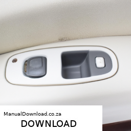
and secure it with bolts.
    – Reconnect the driveshaft and any linkages or electrical connectors that were previously disconnected.

    8. **Refill Gearbox Oil**:
    – Locate the fill plug on the transmission and refill it with the appropriate gearbox oil. Consult your shop manual for the correct type and amount.

    9. **Reconnect the Battery**:
    – Once everything is reassembled, reconnect the battery.

    10. **Test Drive**:
    – Start the engine and take the car for a test drive. Pay attention to the shifting; it should be smooth without any grinding or unusual noises.

    ### Final Notes:
    – This is a high-level overview, and you may encounter specific challenges depending on the condition of your vehicle.
    – Make sure to follow any specific torque settings and procedures outlined in the service manual for your S-Class.
    – If at any point you feel unsure, it’s best to consult with or hire a professional mechanic to ensure the job is done safely and correctly.

    Remember, working on a vehicle can be dangerous if not done properly, so always prioritize safety.
    A vacuum pump is a vital component in many automotive systems, particularly in vehicles equipped with internal combustion engines. Its primary function is to create a vacuum, or negative pressure, which is essential for various operations within the vehicle. One of the most common applications of a vacuum pump is in the brake booster system. In this context, the vacuum pump generates a vacuum that assists in amplifying the force applied to the brake pedal, making it easier for the driver to engage the brakes effectively. This is especially important in vehicles with turbocharged engines, which may not generate sufficient manifold vacuum at low engine speeds.

    In addition to brake assist, vacuum pumps can also be used for other functions, such as operating the HVAC system’s controls, engaging certain engine components, and managing emissions systems. They can be driven mechanically via the engine or can be electric, providing flexibility in design and integration. The efficiency and reliability of a vacuum pump are crucial for maintaining optimal vehicle performance and safety. Over time, vacuum pumps can wear out or develop leaks, leading to a drop in performance or functional failures. Regular maintenance and checks can help ensure that the vacuum pump operates effectively, contributing to the overall efficiency and safety of the vehicle.

    Download Case 1818 Parts-

    discount
    Replacing the gearbox synchronizer on a Case 1818 (or any similar machinery) can seem daunting, but with careful steps and a bit of patience, it can be accomplished even by those with minimal mechanical experience. click here for more details on the download manual…..


      Case 1818 Repower Part 1 The Onan P218 in my Case 1818 skid steer was giving me problems, and finding parts was kinda a pain, so I switched to a much …

      Gear Lever Play Checking 👌👍 #mechanical #garage #video #short tata #1109 #truck #bus #gear #work #mechanical #video #garage #vehicle #information #ytshorts #youtubeshorts #shorts …

    Here’s a simplified guide to help you through the process.

    ### Tools and Materials Needed:
    – Basic hand tools (screwdrivers, wrenches, pliers)
    – Socket set
    – Torque wrench
    – Replacement synchronizer part
    – Clean rags
    – Safety goggles and gloves
    – Container for old fluid (if necessary)

    ### Step-by-Step Guide:

    #### 1. **Preparation:**
    – **Safety First**: Always wear safety goggles and gloves to protect yourself.
    – **Work Area**: Make sure you have a clean, well-lit area to work in. Lay out your tools and parts so that everything is within reach.

    #### 2. **Disconnect the Power Source:**
    – **Turn Off the Machine**: Ensure that the Case 1818 is turned off and cooled down.
    – **Disconnect the Battery**: If applicable, disconnect the battery to prevent any accidental starts.

    #### 3. **Access the Gearbox:**
    – **Remove the Cover**: Locate the gearbox cover. This might involve unscrewing several bolts or screws. Use the correct size tools to avoid stripping any fasteners.
    – **Take Pictures**: Before removing any parts, take pictures for reference. This will help you remember how to reassemble everything.

    #### 4. **Drain the Fluid (if necessary):**
    – **Check for Fluid**: If your gearbox has oil or fluid, you may need to drain it. Look for a drain plug at the bottom of the gearbox.
    – **Remove the Plug**: Use a wrench to carefully remove the drain plug and let the fluid drain into a container.

    #### 5. **Remove the Old Synchronizer:**
    – **Locate the Synchronizer**: Once you have access to the gearbox internals, locate the synchronizer. It is usually a cylindrical part that helps the gears shift smoothly.
    – **Take Out the Synchronizer**: Gently pull the synchronizer out. You may need to wiggle it a bit, but be careful not to damage any surrounding components.

    #### 6. **Install the New Synchronizer:**
    – **Compare Parts**: Check the new synchronizer against the old one to ensure they are identical.
    – **Insert the New Part**: Slide the new synchronizer into place, ensuring it fits snugly.

    #### 7. **Reassemble the Gearbox:**
    – **Replace the Cover**: Once the new synchronizer is in place, reattach the gearbox cover. Make sure to align it properly.
    – **Tighten Bolts**: Use a torque wrench to tighten the bolts to the manufacturer’s specifications (if available). If not, tighten them evenly but do not over-tighten.

    #### 8. **Refill Fluid:**
    – **Add New Fluid**: If you drained the fluid earlier, refill the gearbox with the appropriate type of oil or fluid.
    – **Check Level**: Make sure the fluid level is correct according to the manufacturer’s guidelines.

    #### 9. **Reconnect Everything:**
    – **Reconnect the Battery**: If you disconnected the battery earlier, connect it back.
    – **Double-Check Everything**: Ensure all toolsdownload Case 1818 Parts workshop manual 
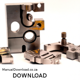
and leftover parts are accounted for.

    #### 10. **Test the Machine:**
    – **Start the Engine**: Turn on the Case 1818 and let it run for a few minutes.
    – **Check for Leaks**: Look for any fluid leaks around the gearbox area.
    – **Test Shifting**: If applicable, test the shifting to ensure the new synchronizer is functioning correctly.

    ### Conclusion:
    Replacing a gearbox synchronizer can be a rewarding experience, and following these steps will help you do it safely and effectively. If you encounter any complications or feel unsure, don’t hesitate to consult the manufacturer’s manual or seek assistance from a professional mechanic. Good luck!
    The transmission pan is a crucial component of an automobile’s transmission system, primarily found in vehicles equipped with automatic transmissions. It serves as a reservoir that holds the transmission fluid, which is essential for lubricating the various moving parts within the transmission, facilitating smooth gear shifts, and cooling the system. Typically made from stamped steel or aluminum, the transmission pan is designed to withstand high temperatures and pressures generated during the operation of the vehicle.

    The pan is located at the bottom of the transmission assembly and is usually sealed with a gasket to prevent fluid leaks. It features a drain plug for easy fluid changes and may include a filter that helps to trap contaminants and debris from circulating within the transmission. Over time, the transmission fluid can become contaminated or break down, leading to potential transmission issues. Regular maintenance, including fluid changes and inspections of the transmission pan, is vital for ensuring optimal performance and longevity of the transmission system.

    In addition to its functional role, the transmission pan can also be a point of aesthetic interest for some automotive enthusiasts, with options for aftermarket pans that feature custom designs or finishes. Overall, the transmission pan plays a vital role in the effective operation of a vehicle’s transmission system, influencing both performance and reliability.

    Download 2002 BMW 525I Service and Repair Manual –

    stores
    Replacing the clutch plate on a BMW 525i involves several steps and requires specific tools and components. click here for more details on the download manual…..


      BMW DENTS FIXED IN MINUTES! BMW 5 Series – 100% Glue Pull Dent Repair (Paintless Dent Removal) Paintless dent removal carried out by Ben at Dents Inc – Cheshire UK This video perfectly demonstrates how important it is to be …

      E30 Progress + E34 525i OVERHEATED! Time to remove the Cylinder Head… While I did say that we get to make the AN lines for the 86 E30 today I completely underestimated the cooler assembly so that will …

    Below is a detailed guide, including descriptions of the tools needed for this task.

    ### Tools and Equipment Needed:

    – **Socket Set**: A complete socket set (metric) will be required, including:
    – **Ratchet**: For turning the sockets.
    – **Extensions**: To reach fasteners in tight spaces.
    – **Universal Joint**: For accessing bolts at angles.

    – **Torque Wrench**: For tightening bolts to the manufacturer’s specifications.

    – **Pliers**: For removing clips and holding components.

    – **Screwdrivers**: Both flat-head and Phillips for various fasteners.

    – **Clutch Alignment Tool**: This tool is crucial for aligning the new clutch disc with the flywheel during installation.

    – **Transmission Jack or floor Jack**: To safely support and lower the transmission.

    – **Creeper or Mechanic’s Mat**: For comfort while working underneath the vehicle.

    – **Brake Cleaner**: To clean the surfaces of the flywheel and clutch components.

    – **Rags or Shop Towels**: For cleaning and wiping away any spilled fluids.

    – **Drip Pan**: To catch any fluids that may leak during the process.

    – **Replacement Clutch Kit**: Ensure you have a complete kit that includes:
    – **Clutch Disc**: The actual friction plate.
    – **Pressure Plate**: The component that presses the clutch disc against the flywheel.
    – **Release Bearing (Throw-out Bearing)**: The bearing that disengages the clutch when the pedal is pressed.

    ### Steps for Clutch Plate Replacement:

    – **Preparation**:
    – Park the vehicle on a flat surface and engage the parking brake.
    Disconnect the negative battery terminal to prevent any electrical shorts.

    – **Remove the Drive Shaft**:
    – Depending on your model, locate and remove the bolts securing the drive shaft to the transmission.
    – Carefully slide the drive shaft out and set it aside.

    – **Access the Transmission**:
    – Remove any components obstructing access to the transmission. This may include the exhaust system, heat shield, or crossmembers.
    – Support the transmission using a transmission jack or floor jack.

    – **Unbolt the Transmission**:
    – Locate the bolts securing the transmission to the engine and remove them using the socket set.
    – Carefully lower the transmission from the engine block. You may need to wiggle it free due to the input shaft being engaged in the clutch.

    – **Remove the Old Clutch Assembly**:
    – Once the transmission is removed, you will have access to the clutch assembly. Remove the pressure plate by unbolting it from the flywheel.
    – Carefully pull off the clutch disc and inspect the flywheel for damage or excessive wear.

    – **Clean the Flywheel**:
    – Use brake cleaner and a rag to clean the surface of the flywheel, removing any debris or oil.

    – **Install the New Clutch Kit**:
    – Position the new clutch disc onto the flywheel. Use the clutch alignment tool to ensure it is centered.
    – Install the new pressure plate over the clutch disc and tighten the bolts in a star pattern to ensure even pressure. Use the torque wrench to apply the correct torque as specified in the manufacturer’s manual.

    – **Replace the Release Bearing**:
    – Install the new release bearing onto the transmission input shaft If applicable.

    – **Reinstall the Transmission**:
    – Carefully lift the transmission back into position, ensuring the input shaft aligns with the clutch disc.
    – Bolt the transmission back to the engine block securely.

    – **Reinstall the Drive Shaft**:
    – Reattach the drive shaft to the transmission, ensuring it is secured with the appropriate bolts.

    – **Reassemble Any Removed Components**:
    – Reinstall any components that were removed to access the transmission, such as the exhaust system or heat shields.

    – **Reconnect the Battery**:
    – Reconnect the negative battery terminal.

    – **Test the Clutch**:
    – Start the vehicledownload BMW 525I workshop manual and test the clutch operation. Ensure that the pedal feels normal and the clutch engages and disengages properly.

    ### Safety Tips:

    – Always wear safety glasses and gloves when working on your vehicle.
    – Make sure the vehicle is securely raised and supported with jack stands If you need to work underneath it.
    If at any point you feel unsure about a step, consult a professional mechanic or refer to the vehicle’s service manual for additional guidance.

    This guide should provide a comprehensive overview of the clutch plate replacement process for a BMW 525i. Always refer to the specific service manual for your vehicle for torque specifications and any model-specific procedures.
    The fan clutch is a crucial component in a vehicle’s cooling system, designed to regulate the operation of the engine’s cooling fan. It plays a vital role in maintaining optimal engine temperatures, ensuring efficiency and preventing overheating. The fan clutch connects the engine’s cooling fan to the water pump shaft and is typically located between the fan blade and the engine.

    There are two common types of fan clutches: thermal and electronic. A thermal fan clutch uses a bi-metallic strip that expands or contracts based on temperature. When the engine reaches a certain temperature, the bi-metallic strip activates a mechanism that engages the fan, allowing it to spin faster and increase airflow through the radiator. This helps dissipate heat more effectively. Conversely, when the engine cools down, the fan clutch disengages, allowing the fan to spin more slowly, which reduces drag on the engine and improves fuel efficiency.

    Electronic fan clutches, on the other hand, utilize electronic sensors and signals from the engine control unit (ECU) to manage fan operation. This allows for more precise control over the cooling system, adapting to varying engine loads and temperatures.

    A malfunctioning fan clutch can lead to overheating, reduced engine performance, and increased fuel consumption. Therefore, regular inspection and maintenance of this component are essential for optimal vehicle operation.

    Download 2004 BMW 760Li (E65/E66) 7 Series OEM Download Service & Repair Manual Software –

    service manual
    Replacing the engine gasket on a BMW 760Li (E65/E66) is a complex task that requires a good understanding of automotive mechanics, as well as some specialized tools. click here for more details on the download manual…..


      bmw e65 760i custom exhaust Sound check after exhaust being modified on my 760i.

      DIY BMW E65 E66 7 series hidden dash menu Dash Camera: http://amzn.to/1Tci2uP UK Shoppers: http://amzn.to/1Slc5wS ******************************************************* All …

    Below is a detailed guide to help you through the process, though it’s important to note that this is a high-level overview. Always refer to a service manual specific to your vehicle for precise instructions and torque specifications.

    ### Tools and Equipment Needed
    1. **Basic Hand Tools**:
    – Socket set (metric)
    – Wrenches (metric)
    – Screwdrivers (flat and Phillips)
    – Torque wrench
    – Pliers

    2. **Specialized Tools**:
    – Engine hoist (if necessary)
    – Gasket scraper or razor blade
    – Torque angle gauge
    – Oil filter wrench
    – Vacuum pump (for vacuum lines)

    3. **Consumables**:
    – New gaskets (OEM recommended)
    – Engine oil
    – Coolant
    – Brake cleaner
    – RTV silicone (if applicable)
    – Engine degreaser

    ### Components Involved
    1. **Engine Gaskets**:
    – **Head Gasket**: Seals the cylinder head to the engine block.
    – **Intake Manifold Gasket**: Seals the intake manifold to the cylinder head.
    – **Exhaust Manifold Gasket**: Seals the exhaust manifold to the cylinder head.
    – **Valve Cover Gasket**: Seals the valve cover to the cylinder head.
    – **Oil Pan Gasket**: Seals the oil pan to the engine block.

    2. **Engine Components**:
    – **Cylinder Head**: Contains the combustion chambers, valves, and camshafts.
    – **Intake Manifold**: Directs air and fuel into the engine.
    – **Exhaust Manifold**: Directs exhaust gases out of the engine.
    – **Valve Cover**: Covers the top of the engine cylinder head.
    – **Oil Pan**: Holds the engine oil.

    ### Steps for Engine Gasket Replacement

    #### 1. Preparation
    – **Disconnect the Battery**: Ensure safety by disconnecting the negative terminal.
    – **Drain Fluids**: Drain engine oil and coolant to prevent spills.

    #### 2. Remove Components
    – **Intake Manifold**:
    – Disconnect throttle body, vacuum lines, and electrical connectors.
    – Unbolt the intake manifold and carefully remove it.

    – **Exhaust Manifold**:
    – Disconnect exhaust pipes and associated sensors.
    – Unbolt and remove the exhaust manifold.

    – **Valve Covers**:
    – Remove ignition coils and spark plugs (if applicable).
    – Unbolt the valve covers and lift them off.

    – **Cylinder Head**:
    – Remove any remaining components attached to the cylinder head (e.g., camshaft timing chain, sensors).
    – Unbolt the cylinder head in the correct sequence (refer to service manual).
    – Carefully lift the cylinder head off the engine block.

    #### 3. Clean Surfaces
    – **Gasket Removal**: Use a gasket scraper or razor blade to remove old gaskets. Be careful not to scratch the mating surfaces.
    – **Clean Surfaces**: Use brake cleaner and a clean rag to remove oil and debris from the mating surfaces.

    #### 4. Install New Gaskets
    – **Head Gasket**: Place the new head gasket onto the engine block, ensuring it’s aligned properly.
    – **Intake and Exhaust Gaskets**: Install the new gaskets for the intake manifold and exhaust manifold.
    – **Valve Cover Gasket**: Place the new gasket on the valve cover.

    #### 5. Reassemble Components
    – **Cylinder Head**: Carefully lower the cylinder head onto the block, ensuring the gasket stays in place.
    – **Torque Head Bolts**: Torque the cylinder head bolts in the specified sequence and to the specified torque settings (refer to service manual).

    – **Reinstall Valve Covers**: Bolt the valve covers back into place.
    – **Reattach Exhaust Manifold**: Position the exhaust manifold with new gasketsdownload BMW 760Li E65 E66 7 OEM workshop manual and bolt it down.
    – **Reattach Intake Manifold**: Position and bolt the intake manifold.

    #### 6. Reconnect Components
    – Reconnect all electrical connections, vacuum lines, and any other components that were removed.

    #### 7. Fill Fluids
    – **Engine Oil**: Replace the oil filter and fill the engine with the appropriate type and amount of engine oil.
    – **Coolant**: Refill the cooling system with the recommended coolant.

    #### 8. Final Steps
    – **Reconnect Battery**: Reconnect the negative battery terminal.
    – **Start the Engine**: Check for leaks and ensure the engine runs smoothly.
    – **Check Systems**: Monitor for any warning lights and check fluid levels again after running the engine for a short period.

    ### Important Notes
    – **Safety First**: Always wear safety glasses and gloves when working on a vehicle.
    – **Consult Manual**: Refer to the BMW service manual for specific torque values and sequences.
    – **Consider Professional Help**: If you lack experience, consider seeking help from a professional mechanic, as mistakes can lead to severe engine damage.

    This guide provides an overview of the engine gasket replacement process for a BMW 760Li E65/E66. Proper care and attention to detail are essential for a successful repair.
    A brake disc, also known as a brake rotor, is a critical component of a vehicle’s braking system, designed primarily to slow down or stop the vehicle by converting kinetic energy into thermal energy through friction. Typically made from cast iron or carbon composite materials, brake discs are circular plates that are mounted to the wheel hub. When the driver presses the brake pedal, hydraulic pressure is applied to brake calipers, which contain brake pads that clamp down onto the surface of the brake disc. This contact generates friction, which slows the rotation of the wheel and ultimately brings the vehicle to a stop.

    Brake discs come in various designs, including vented, slotted, and drilled types, each engineered to improve performance under different conditions. Vented discs feature internal cooling channels that enhance heat dissipation, reducing the risk of brake fade during prolonged use. Slotted or drilled discs have grooves or holes that allow for better gas and moisture dissipation, further improving grip and performance, especially in wet conditions.

    The maintenance of brake discs is paramount for vehicle safety. Over time, they can wear down or become warped due to excessive heat, necessitating regular inspections and replacements. High-performance vehicles may use upgraded brake discs to enhance stopping power and minimize fade during extreme driving conditions. Overall, the brake disc is an essential element in ensuring effective braking performance and vehicle safety.

    Download 2008 BMW 1-Series COUPE E82 Service and Repair Manual –

    workshop manual
    Replacing the transmission fluid sensor on a BMW 1 Series Coupe (E82) can seem daunting, especially if you have little mechanical experience. click here for more details on the download manual…..


      BMW 1 Series Hidden Features!

      CHEAP APPLE CARPLAY HEAD UNIT FOR MY BMW 1 SERIES 135i E82 In this video, I’m showing you how to install an Apple Carplay/Android Auto head unit into a BMW 1 series E82. This unit is a great …

    However, with the right tools and a step-by-step approach, you can tackle this task. Here’s a simplified guide to help you through the process.

    ### Tools and Materials Needed:
    1. **Tools:**
    socket set (including 10mm and 13mm sockets)
    – Flathead screwdriver
    – Ratchet wrench
    – Torque wrench (for reassembly)
    – Pliers
    – Oil catch pan

    2. **Materials:**
    – New transmission fluid sensor
    – New transmission fluid (if necessary)
    – Rags or paper towels
    – Safety glasses and gloves

    ### steps to Replace the Transmission Fluid Sensor:

    #### 1. **Safety First**
    – Park your car on a level surface and turn off the engine.
    – Engage the parking brake.
    wear safety glasses and gloves to protect yourself from any fluid spills.

    #### 2. **Lift the Car**
    – Use a jack to lift the front of the car and secure it on jack stands. This gives you better access to the transmission area.

    #### 3. **Locate the Transmission Fluid Sensor**
    – The transmission fluid sensor is typically located on the side of the transmission. It looks like a small plug and is usually near the fluid pan.
    – You may need to remove a cover or some components to access it better.

    #### 4. **Drain the Transmission Fluid**
    – Place an oil catch pan underneath the transmission to catch any fluid that may leak out.
    – Using a socket wrench, remove the bolts from the transmission pan (if necessary) to drain the fluid. Be careful, as the fluid can be hot and messy.

    #### 5. **Disconnect the Old Sensor**
    – Once you have access to the sensor, gently disconnect the wiring harness. There may be a clip or tab that you need to press to release it.
    – Use the appropriate socket to unscrew the sensor from the transmission. Be cautious not to drop any debris into the transmission.

    #### 6. **Install the New Sensor**
    – Take your new sensor and screw it into place where the old One was. Use your hand to tighten it first, then use a torque wrench to tighten it to the manufacturer’s specifications (check your manual for the exact torque value).
    – Reconnect the wiring harness to the new sensor, ensuring it clicks into place securely.

    #### 7. **Reassemble the Transmission Pan (if removed)**
    – If you removed the transmission pan, clean any old gasket material off the mating surface.
    – Place a new gasket or sealant on the pan if required.
    – Reattach the pan and tighten the bolts in a crisscross pattern to ensure even pressure.

    #### 8. **Refill Transmission Fluid**
    – If you drained the fluid, refill the transmission with the correct typedownload BMW 1 Series COUPE E82 workshop manual and amount of fluid as specified in your owner’s manual.
    – Use a funnel to avoid spills and check for any leaks around the sensor area.

    #### 9. **Lower the Car**
    – Carefully remove the jack stands and lower the car back to the ground.

    #### 10. **Test the New Sensor**
    – Start the car and let it run for a few minutes. Check the dashboard for any warning lights related to the transmission.
    – Take the car for a short test drive to ensure everything is functioning properly.

    ### Final Tips:
    – Always refer to your vehicle’s service manual for specific instructions and torque specifications.
    – If at any point you feel unsure, it may be wise to consult a professional mechanic.

    By following these steps, you should be able to replace the transmission fluid sensor on your BMW 1 Series Coupe E82. good luck!
    Keyless entry is an advanced automotive feature that enhances convenience and security for vehicle users. This system allows drivers to unlock and start their vehicles without the need for a traditional physical key. Instead, keyless entry utilizes a remote key fob or a smart key, which communicates wirelessly with the car’s electronic control unit.

    When a driver approaches the vehicle with the key fob in their pocket or bag, sensors embedded in the car detect the fob’s proximity. This triggers the system to unlock the doors automatically, often accompanied by a welcoming light sequence. The driver can then enter the vehicle without fumbling for keys. Once inside, starting the engine is as simple as pressing a button, provided that the key fob is within the car’s interior.

    Keyless entry systems often come with additional security features. For example, they may include rolling code technology, which changes the access code each time the key fob is used, making it significantly harder for potential thieves to replicate the signal. Some systems also offer features like remote locking and unlocking, allowing users to control their vehicle from a distance.

    Overall, keyless entry systems represent a significant advancement in automotive technology, providing enhanced ease of use while also improving vehicle security. As vehicles become increasingly integrated with smart technology, keyless entry is likely to become a standard feature in many new models.

    Download 2019 Audi S5 Download Service & Repair Manual –

    owners manual
    Performing engine diagnostics on an Audi S5 can seem daunting, but breaking it down into simple steps can make it manageable, even for those with little mechanical experience. click here for more details on the download manual…..


      NEW Wheels for the Audi S5! Looks AMAZING! Welcome back to the channel! In this video, we put are removing the stock wheels off the S5 to put on a set of aftermarket ones!

      B9 Audi S4/S5/RS4/RS5 Driveshaft Bearing Carrier UPGRADE!👀👌🏼😁 The JXB Performance Driveshaft Center Support Carrier Bearing Upgrade for the B9 Audi S4/S5/RS4/RS5 Has a Street(softer) …

    Here’s an easy-to-follow guide:

    ### 1. **Gather Your Tools**
    – **OBD-II Scanner**: This is a diagnostic tool that reads trouble codes from your vehicle’s computer. You can purchase one or find a local auto parts store that will lend or rent you one.
    – **Basic Hand Tools**: A set of screwdrivers, wrenches, and pliers may come in handy if you need to inspect any components.

    ### 2. **Check for Warning Lights**
    – Sit in your Audi S5 and turn the ignition to the “on” position (without starting the engine).
    – Look for any warning lights on the dashboard, particularly the check Engine light (CEL). If it’s on or blinking, it indicates a problem.

    ### 3. **Connect the OBD-II Scanner**
    – Locate the OBD-II port in your vehicle. In the Audi S5, it’s usually found below the dashboard near the steering column.
    – Plug the OBD-II scanner into the port.
    – Turn the ignition on (again, don’t start the engine).
    – Follow the scanner’s instructions to read the trouble codes. These codes will give you clues about what might be wrong.

    ### 4. **Interpret the Codes**
    – Once the scanner retrieves the codes, write them down. You can look them up in the scanner’s manual or search online for their meanings.
    – Common codes may point to issues like misfires, oxygen sensor problems, or issues with the catalytic converter.

    ### 5. **Visual Inspection**
    – Open the hood of your Audi S5.
    – Look for any obvious signs of trouble:
    – **Leaks**: Look for any fluids leaking (oil, coolant, etc.).
    – **Worn Belts**: Check the condition of the belts; they should not be cracked or frayed.
    – **Loose Connections**: Ensure all electrical connections are secure, especially those related to the Engine sensors.

    ### 6. **Check Fluid Levels**
    – **Engine Oil**: Use the dipstick to check the oil level. Make sure it’s at the right level and the oil looks clean.
    – **Coolant**: Check the coolant reservoir to ensure it’s at the proper level.
    – **Brake Fluid**: Make sure your brake fluid is at the recommended level.

    ### 7. **Test Drive and Observe**
    – If safe, take the car for a short drive. Pay attention to any unusual sounds, vibrations, or performance issues.
    – If the check Engine light comes back on, make a note of any changes in performance.

    ### 8. **Seek Professional Help**
    – If you find trouble codes that indicate serious issues (like Engine misfires or transmission problems), or if you’re uncomfortable performing any repairs, it’s best to consult a professional mechanic.

    ### 9. **Keep Records**
    – Document any codes, symptoms,download Audi S5 workshop manual and repairs. This information can be very helpful for a mechanic if you need to take the car in for professional diagnostics.

    ### Conclusion
    By following these steps, you can perform basic Engine diagnostics on your Audi S5. Remember, while this guide helps you identify potential issues, some problems may require professional expertise to fix. Don’t hesitate to seek help if you’re unsure about anything!
    The trunk light, also known as the cargo light or boot light, is a vital component in automotive design, primarily serving the function of illuminating the trunk or cargo area of a vehicle. Typically located on the underside of the trunk lid or mounted on the side walls of the trunk, this small but essential light activates when the trunk is opened, providing visibility in low-light situations. Its primary purpose is to facilitate the easy loading and unloading of items, ensuring that drivers can see clearly when accessing their belongings, especially during nighttime or in poorly lit conditions.

    Trunk lights are generally powered by the vehicle’s electrical system and can be LED or incandescent bulbs. LED lights are increasingly preferred due to their energy efficiency, longer lifespan, and brighter illumination. The light is usually wired to a switch that is activated when the trunk lid is opened, which may be a mechanical switch or a sensor that detects the lid’s position.

    In addition to their practical function, trunk lights also enhance safety by preventing accidents or injuries that could occur from fumbling in the dark. Some modern vehicles may even include additional features, such as automatic shut-off timers or integration with the vehicle’s interior lighting system. Overall, the trunk light is a small yet significant feature that contributes to the overall functionality and convenience of a vehicle.

    Download Kia Venga 2010 Service Manual –

    bookshop
    Installing a suspension lift kit on a Kia Venga can enhance its off-road capabilities and improve ground clearance. click here for more details on the download manual…..


      Kia Venga MPV review – CarBuyer Kia Venga MPV 2014 review: http://bit.ly/19YuYOS Subscribe to the Carbuyer YouTube channel: http://bit.ly/17k4fct Subscribe to …

      Rear End Noise? Diagnose and Fix a Differential in Your Car, Truck, or SUV If you are hearing clunking, rattling or grinding noises in the rear end of your rear wheel or four wheel drive vehicle, it may be a …

    However, this process requires careful planning and execution. Below is a detailed guide outlining the tools and steps needed for a successful installation.

    ### Tools Required

    – **Socket Set**: A complete metric socket set, including ratchets and extensions, to remove and tighten bolts.
    – **Wrench Set**: A comprehensive set of combination wrenches for accessing tight spaces.
    – **Torque Wrench**: To ensure all bolts are tightened to the manufacturer’s specifications.
    – **Jack and Jack Stands**: A hydraulic jack for lifting the vehicle and jack stands for safety while working underneath.
    – **Lug Wrench**: To remove the wheels.
    – **Pry Bar**: For leveraging components, especially when removing old parts.
    – **Spring Compressors**: Essential for safely compressing coil springs during removal and installation.
    – **Cutting Tool**: A saw or cutting torch may be necessary if any modifications to brackets or body panels are required.
    – **Drill and Drill Bits**: For creating new mounting points if needed.
    – **Measuring Tape**: To measure suspension heights and ensure proper alignment.
    – **Grease Gun**: To lubricate moving parts and fittings.
    – **Safety Gear**: Gloves, goggles, and a dust mask to protect yourself during the installation.

    ### Installation Steps

    – **Preparation**:
    – Park the Kia Venga on a level surface, engage the parking brake, and disconnect the battery to prevent any electrical issues during the installation.
    – Gather all tools and the lift kit parts to ensure everything is on hand.

    – **Raise the Vehicle**:
    – Use the jack to lift the front or rear of the vehicle, depending on which part of the suspension you are working on first.
    – Secure the vehicle with jack stands to ensure safety while you are working underneath it.

    – **Remove Wheels**:
    – Using the lug wrench, remove the lug nuts and take off the wheels to access the suspension components.

    – **Disconnect Suspension Components**:
    – Start with the lower control arm, sway bar links, and shocks. Use the socket and wrench set to remove the bolts carefully.
    – Depending on the lift kit design, you may need to remove the coil springs. Use spring compressors to safely compress the springs before removal.

    – **Install Lift Kit Components**:
    – Follow the manufacturer’s instructions for the lift kit, as each kit may have different components and installation methods.
    install any new brackets, spacers, or lift struts as specified. Ensure that each component is aligned correctly.
    – If the kit includes new shocks, replace the old shocks with the new ones at this stage.

    – **Reassemble Suspension**:
    – Once the lift kit components are installed, reattach the lower control arm, sway bar links, and any other suspension parts you previously removed.
    – Ensure all bolts are tightened to the specified torque settings using the torque wrench.

    – **Adjust Alignment**:
    – After the suspension components are reattached, checkdownload Kia Venga workshop manual and adjust the alignment if necessary. this is crucial to ensure proper handling and tire wear.

    – **Reinstall Wheels**:
    – Put the wheels back on and hand-tighten the lug nuts.
    – Lower the vehicle back to the ground, and then use the torque wrench to tighten the lug nuts to the manufacturer’s specifications.

    – **Final Checks**:
    – Reconnect the battery and check for any loose parts or unusual noises.
    – Take the vehicle for a short test drive to ensure the lift kit is functioning correctly and there are no issues.

    – **Post-Installation Maintenance**:
    – Regularly check the suspension components and alignment, especially after the first few hundred miles, to ensure everything remains secure and properly adjusted.

    ### Notes

    – Always consult the lift kit’s installation manual for model-specific instructions.
    – If you’re unsure about any part of the installation, consider seeking professional assistance.
    – Ensure the lift kit is suitable for the Kia Venga, as incorrect kits can lead to handling issues or damage.

    Following these detailed steps should help you successfully install a suspension lift kit on your Kia Venga. Remember to prioritize safety and accuracy throughout the process.
    The heater core is a vital component of a vehicle’s heating and cooling system, playing a crucial role in providing interior comfort during cold weather. It is essentially a small radiator located within the dashboard of the car, positioned in such a way that it can transfer heat from the engine’s coolant to the air that enters the cabin.

    The heater core operates by circulating hot coolant from the engine through its channels. As the hot coolant passes through the core, a fan blows air over it, allowing the heat to transfer to the air. this heated air is then directed into the vehicle’s cabin through the ventilation system, warming the interior space for the occupants.

    Heater cores are usually made of aluminum or copper and are designed in a way that maximizes surface area to enhance heat exchange efficiency. Over time, heater cores can become clogged with debris or suffer from corrosion, leading to diminished heating performance or even coolant leaks inside the cabin. Symptoms of a Failing heater core can include a sweet smell of coolant, foggy windows, or a lack of hot air from the vents.

    Maintaining the heater core is important not only for comfort but also for the overall efficiency of the vehicle’s heating system. Regular inspections and coolant changes can help prolong its lifespan and ensure optimal operation.