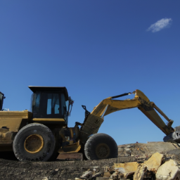
Repairing a manual transmission on a Komatsu D65E-12 dozer requires a systematic approach, proper tools, and a good understanding of the machine’s components. click here for more details on the download manual…..
- Engine over hauling bulldozer,dozer,bulldozer (product category),bulldozers,buldozer,bulldozer (invention),komatsu limited (business operation) …
- Komatsu D65-18 and D85-18 operator controls An inside look at Komatsu’s D65-18 and D85-18 operator controls. Learn more about the D65EX-18: https://bit.ly/2AKy92T Learn …
Below is an overview of the process, including detailed descriptions of the components involved.
### Components of the Manual Transmission
1. **Transmission Housing**: The outer shell that contains all internal components. It’s made of durable materials to withstand High stress and heat.
2. **Input Shaft**: Connects to the engine and transfers power to the transmission.
3. **Output Shaft**: Transfers power from the transmission to the final drive.
4. **Gears and Synchronizers**: These components allow for smooth shifting between different gears.
5. **Clutch Assembly**: Engages and disengages the engine from the transmission. Includes the clutch disc, pressure plate, and release bearing.
6. **Shift Forks and Linkage**: Mechanisms that allow the driver to select different gears.
7. **Bearings and Seals**: Support rotating components and prevent fluid leaks.
8. **Oil Pump and Fluid Reservoir**: Circulates transmission fluid to lubricate and cool the transmission.
### Tools Required
– Basic hand tools (sockets, wrenches, screwdrivers)
– Torque wrench
– Transmission jack
– Pry bar
– Seal puller
– Gear puller
– clean rags
– Oil catch pan
– Gasket scraper
– Safety equipment (gloves, goggles)
### Step-by-Step Repair Process
#### 1. Preparation
– **Safety First**: Ensure the dozer is parked on a level surface. Engage the parking brake and Disconnect the battery.
– **Documentation**: Refer to the service manual for the specific model, noting specifications and torque values.
#### 2. Accessing the Transmission
– **Remove the Belly Pan**: If applicable, remove the belly pan to gain access to the transmission.
– **Disconnect the Drive Shafts**: Remove the bolts connecting the drive shafts to the output shaft. Use a wrench or socket set to carefully detach them.
– **Disconnect the Clutch Linkage**: Remove the linkage connected to the clutch pedal. this may involve unbolting brackets or removing cotter pins.
#### 3. Removing the Transmission
– **Support the Transmission**: Use a transmission jack to support the transmission.
– **Unbolt the Transmission**: Locate and remove the bolts securing the transmission to the engine and transmission housing. Carefully lower the transmission once all bolts are removed.
#### 4. Disassembling the Transmission
– **Remove the Housing**: Once the transmission is on a workbench, remove the bolts from the transmission housing.
– **Inspect Internal Components**: Carefully take apart the transmission to access the internal components. Pay attention to the arrangement of gears, bearings, and other parts. Take pictures or make diagrams if necessary for reassembly.
– **Check for Wear**: Inspect gears, bearings, and seals for wear or damage. Replace any components that are worn beyond specifications.
#### 5. Replacing Components
– **Replace Worn Gears or Synchros**: If any gears or synchronizers are damaged, replace them. Ensure that the new components match the specifications.
– **Install New Seals**: Replace seals to prevent leaks. Ensure they are properly seated using a seal driver if necessary.
– **Install New Bearings**: If bearings are worn, replace them. Ensure they are adequately lubricated before installation.
#### 6. Reassembly
– **Reassemble the Transmission**: Carefully reassemble the transmission in the reverse order of disassembly, ensuring all parts are aligned correctly.
– **Torque Specifications**: Use a torque wrench to tighten bolts to the manufacturer’s specifications as per the service manual.
#### 7. Reinstallation
– **Reconnect the Transmission**: Use the transmission jack to lift the transmission back into place. Secure it to the engine with the appropriate bolts and torque them to specification.
– **Reconnect Drive Shafts**: Reattach the drive shafts to the output shaft, ensuring they are properly aligned.
#### 8. Reconnect Clutch Linkage
– **Reattach Linkage**: Reconnect the clutch linkage to the pedal and check for proper operation.
#### 9. Fill with Transmission Fluid
– **Add Fluid**: Refill the transmission with the specified type and amount of transmission fluid. Check the levels according to the service manual.
#### 10. Testing
– **Reconnect Battery**: Reconnect the battery and start the engine.
– **Test Drive**: Carefully test the dozer to ensure that the transmission operates smoothly through all gears.
### Final Checks
– **Check for Leaks**: Inspect around the transmission and seals for any signs of fluid leaks.
– **Monitor Performance**: Monitor the operation of the transmission during use and address any irregularities.
### Conclusion
Manual transmission repair on a Komatsu D65E-12 is a detailed process that requires attention to detail and adherence to safety protocols. Always refer to the specific service manual for your model for the most accurate instructions and specifications. If you’re unsure or uncomfortable with any part of the process, it may be best to consult a professional mechanic.
The trunk lid, also known as the tailgate or boot lid, is a crucial component of a vehicle that serves several functional and aesthetic purposes. Typically located at the rear of a car, it provides access to the trunk or cargo area, enabling drivers and passengers to store and retrieve items. The design and functionality of trunk lids can vary significantly based on the type of vehicle—sedans, hatchbacks, SUVs, and coupes each have distinct trunk lid styles that cater to their respective designs and user needs.
Trunk lids are generally constructed from materials such as steel, aluminum, or composite materials, balancing weight, strength, and cost-effectiveness. Many modern trunk lids are designed with aerodynamics in mind, contributing to the overall efficiency of the vehicle by reducing drag. Additionally, they often feature insulation and weather stripping to protect the contents from moisture and noise.
Mechanically, trunk lids can be operated manually or electronically, with some vehicles featuring power-operated systems that allow the lid to be opened or closed with the push of a button. Safety features such as trunk release mechanisms, locking systems, and sometimes even sensors to prevent accidental closure enhance their usability. Moreover, the trunk lid often incorporates design elements that contribute to the vehicle’s overall aesthetic appeal, including integrated spoilers, lights, and branding elements, blending functionality with style.
A sway bar link, also known as an anti-roll bar link or stabilizer link, is an essential component of a vehicle’s suspension system. It connects the sway bar (or anti-roll bar) to the vehicle’s suspension, typically linking it to the control arms or struts. The sway bar itself helps to minimize body roll during cornering by redistributing weight from one side of the vehicle to the other, enhancing stability and handling. The sway bar link plays a crucial role in this process by allowing the sway bar to pivot while maintaining a connection to the suspension system.
Sway bar links are usually made of metal and may include rubber bushings or ball joints to accommodate movement and absorb shocks. Over time, these links can wear out, leading to increased body roll, noise, or instability during turns. Regular inspection and replacement of worn sway bar links are vital for maintaining optimal vehicle handling and safety.
Repairing the suspension crossmember on a Komatsu D65E-12 dozer involves several key components and steps. Here are the main components and considerations for the repair process:
### 1. **Crossmember Structure**
– The crossmember is a critical structural component that provides support for the dozer’s undercarriage. It connects various parts of the frame and must be inspected for cracks, corrosion, or deformation.
### 2. **Inspection and Assessment**
– Before starting repairs, thoroughly inspect the crossmember for any signs of wear or damage. Check for cracks, bent sections, or loose connections. This assessment will help determine whether the crossmember can be repaired or needs replacement.
### 3. **Removal of the Crossmember**
– To repair or replace the crossmember, it may need to be removed from the machine. This typically involves:
– **Disconnecting Components:** Detach any components that are connected to the crossmember, such as suspension links, hydraulic lines, or electrical wiring.
– **Support Structure:** Use supports to hold up the machine and maintain stability while the crossmember is being removed.
– **Bolts and Fasteners:** Remove the bolts and fasteners securing the crossmember to the frame. This may require specific tools like impact wrenches or socket sets.
### 4. **Repair Process**
– Depending on the type of damage, repairs can include:
– **Welding:** For cracks, welding may be necessary to restore structural integrity. Ensure proper welding techniques are used and consider the metal type.
– **Reinforcement:** If the crossmember is weak but not severely damaged, adding reinforcement plates can enhance strength.
– **Replacement:** If the crossmember is too damaged to repair, sourcing a new or refurbished part may be necessary.
### 5. **Reinstallation**
– Once repairs are complete, the crossmember must be reinstalled:
– **Alignment:** Ensure proper alignment with the frame and other components.
– **Fastening:** Secure with appropriate bolts and fasteners, following the specified torque settings outlined in the manual.
### 6. **Final Inspection**
– After reinstallation, conduct a thorough inspection to ensure everything is properly secured and functioning. Check for any signs of misalignment or stress on the crossmember.
### 7. **Testing**
– Before returning the dozer to service, conduct a test run to ensure that the suspension system operates correctly and that the repair has resolved any issues.
### Tools Required
– Wrenches and sockets
– Torque wrench
– Welding equipment (if needed)
– Lifting equipment (hoists, jacks)
– Safety gear (gloves, goggles)
### Safety Precautions
– Always follow safety protocols when working on heavy machinery.
– Use appropriate lifting techniques and equipment to prevent accidents.
By following these components and steps, you can effectively perform a suspension crossmember repair on a Komatsu D65E-12 dozer. Always refer to the specific repair manual for detailed instructions and specifications.