Download 2004 SKODA Fabia Combi Download Service & Repair Manual –

get
Adjusting the transmission band on a Skoda Fabia Combi is a task that typically requires some mechanical knowledge and tools. click here for more details on the download manual…..


    USED Skoda Fabia RS – Common problems and should you buy one? | ReDriven used car review Have peace of mind when getting a used car. Buy a Vehicle History Check now! https://bit.ly/4b94XPc We’re all about those …

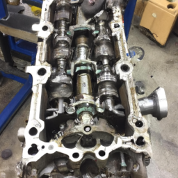
    how to replace easy transmission (gear) & differential oil with tool|demo in skoda fabia|auto… hello.. friends is video me gear or differential oil kese fast change kar sakte he ek tool ki madadse dikhaya gaya he.. ye tool oil …

However, I can break it down into simple steps for you. Please note that this is a general guideline, and it’s always best to consult the owner’s manual or a professional mechanic if you’re unsure. Here’s how you can approach it:

### What You Need:
– Basic hand tools (wrenches, sockets)
– A Jack and Jack stands (for safety)
– A torque wrench (if available)
– A service manual for the Skoda Fabia Combi (for specific torque settings and procedures)

### Steps to Adjust the Transmission Band:

1. **Safety First**:
– Park the car on a flat surface.
– Turn off the engine and remove the keys.
– Engage the parking brake to prevent the car from rolling.

2. **Lift the Vehicle**:
– Use a Jack to lift the front of the car and securely place it on Jack stands. This will provide you with enough space to work underneath the car.

3. **Locate the Transmission Band**:
– The transmission band is found on the transmission itself, which is usually located under the car towards the middle or rear.
– You may need to remove a cover or shield to access it. Consult your service manual for the exact location.

4. **Identify the Adjustment Points**:
– There will typically be a bolt or screw on the band that needs to be adjusted. Make sure you understand which way to turn it to either tighten or loosen the band.

5. **Check the Current Tension**:
– Before making any adjustments, check the current tension of the band. This might require a specific tool or method outlined in the service manual.

6. **Adjust the Band**:
– Using the appropriate tool, turn the adjustment bolt:
– **To tighten**: Turn the bolt clockwise.
– **To loosen**: Turn the bolt counterclockwise.
– Make small adjustments, often no more than a quarter turn at a time.

7. **Recheck the Tension**:
– After making adjustments, check the band tension again to ensure it’s within the specified range mentioned in the service manual.

8. **Reassemble Everything**:
– If you removed any covers or shields, reattach them securely.
– Ensure all tools are removed from under the car.

9. **Lower the Vehicle**:
– Carefully remove the Jack stands and lower the vehicle back to the ground.

10. **Test Drive the Car**:
– Start the car and take it for a short drive to ensure everything is so it’s essential to be cautious and precise. If you have any doubts, don’t hesitate to reach out for professional assistance.
A door handle is a crucial component of a vehicle that serves both functional and aesthetic purposes. Typically located on the exterior and interior of a car door, the door handle allows passengers and drivers to open and close the door easily. Exterior handles are designed for quick access to the vehicle, while interior handles enable occupants to exit or enter the car comfortably.

Most modern door handles are made from durable materials such as plastic, metal, or a combination of both, designed to withstand wear and tear from daily use and exposure to various weather conditions. The design of door handles can vary widely, ranging from traditional pull handles to more advanced systems like touch-sensitive or keyless entry mechanisms. Some vehicles are equipped with electronic handles that allow the doors to open automatically when the key fob is within proximity.

In addition to their primary function, door handles contribute to the overall design and style of a vehicle. Manufacturers often design them to complement the car’s aesthetics, integrating them seamlessly into the bodywork for a sleek, modern appearance. Furthermore, safety features are frequently incorporated into door handles, such as child locks and anti-theft systems, ensuring that they not only provide convenience but also enhance the vehicle’s security. Overall, the door handle is an essential element of automotive design, combining practicality with visual appeal.

Download Case IH 267B, 301B Operators Service Manual –

workshop manual
Shifting detent repair on a Case IH 267B or 301B series tractor involves several steps and requires specific tools and parts. click here for more details on the download manual…..


    PEUGEOT DESTRUYÓ su propia MARCA Existió alguna vez una marca europea símbolo de comodidad, lujo, calidad y silencio, pero hoy, Peugeot, solo significa dolores …

    Manual override of a lippert slide out Nothing strikes fear into a camper more than pushing the slide button and nothing happens. Whether its a power failure or a motor …

Below is a detailed guide with an explanation of the tools and their purposes.

– **Safety Gear**
– **Safety Glasses**: Protects your eyes from debris during the repair.
– **Gloves**: Provides hand protection and improves grip on tools.

– **Basic Tools**
– **Wrench Set**: Used to loosen and tighten bolts and nuts on the tractor. A combination of metric and standard wrenches may be required depending on the specific bolts used in the shifting mechanism.
– **Socket Set**: Allows for easier access to bolts in tight spaces. A ratchet handle with various socket sizes will speed up the removal and installation process.
– **Screwdriver Set**: Flat-head and Phillips screwdrivers are necessary for removing any covers or panels that may obstruct access to the detent assembly.

– **Specialized Tools**
– **Pliers**: For gripping and manipulating small components or retaining clips.
– **Torque Wrench**: Ensures that bolts are tightened to the manufacturer’s specifications, preventing over-tightening or under-tightening, which can lead to further issues.
– **Pick Tool**: Useful for removing O-rings or seals without causing damage.

– **Replacement Parts**
– **Detent Spring**: A spring that provides the tension necessary for the detent mechanism to click into place. If it is worn or broken, it will need replacement.
– **Detent Ball**: A small ball that fits into the detent mechanism. If it is chipped or worn, it may not hold the gear in place properly.
– **O-rings or Seals**: Depending on the condition of your current seals, they may need replacing to prevent fluid leaks.

– **Repair Procedure**
– **Identify the Problem**: Before starting the repair, determine if the issue is with the detent ball, spring, or surrounding components.
– **Remove the Shifter Cover**: Use screwdrivers to remove any screws or bolts securing the shifter cover. Carefully set the cover aside to avoid damaging any gaskets.
– **Access the Detent Assembly**: Once the cover is removed, locate the detent mechanism. This may require removing additional components depending on your specific model.
– **Remove the Detent Assembly**: Use wrenches or a socket set to remove any bolts holding the detent assembly in place. Take note of how pieces are oriented for reassembly.
– **Inspect Components**: Check the condition of the detent ball, spring, and any seals. Replace any worn or damaged components with new parts.
– **Reassemble the Detent Mechanism**: Carefully reassemble the detent mechanism, ensuring that the new parts are correctly seated. Use the torque wrench to tighten bolts to the specified torque settings.
– **Reinstall the Shifter Cover**: Once reassembly is complete, replace the shifter coverdownload Case IH 267B 301B s workshop manual and secure it with screws or bolts.
– **Test the Mechanism**: Start the tractor and test the shifting to ensure that the detent functions correctly and engages smoothly.

– **Post-Repair Checks**
– **Fluid Levels**: After repair, always check the hydraulic fluid levels if your tractor uses hydraulics in the shifting mechanism. Top off if necessary.
– **Visual Inspection**: Conduct a thorough inspection for any signs of leaks or misalignment after the repair is done.

By following these steps and using the appropriate tools, you can effectively perform a shifting detent repair on a Case IH 267B or 301B tractor. Always refer to the specific service manual for any model-specific instructions or torque specifications.
A hubcap, also known as a wheel cover, is a decorative disc that is placed over the central portion of a vehicle’s wheel. Its primary purpose is to enhance the aesthetic appeal of the wheel and the overall appearance of the vehicle while also serving practical functions. Hubcaps are commonly made from materials such as plastic, aluminum, or steel, and they come in a variety of designs, colors, and finishes, allowing for customization that matches the style of the car.

In addition to their decorative role, hubcaps help protect the wheel’s lug nuts and hub assembly from dirt, debris, and corrosion, which can prolong the life of these components and reduce the need for maintenance. They can also contribute to the vehicle’s aerodynamics by smoothing out the airflow around the wheels, potentially improving fuel efficiency.

Hubcaps can be either full covers that encapsulate the entire wheel or partial covers that only shield certain areas. Some vehicles come equipped with hubcaps as standard features, while others may have alloy wheels that do not require them. Moreover, hubcaps can be easily replaced if damaged, making them a practical accessory for car owners. Overall, while often overlooked, hubcaps play a significant role in both the functionality and aesthetics of automobiles.

Download Mitsubishi Eclipse 2 1995 Service Repair Manual –

get
Repairing a transmission fluid leak on a Mitsubishi Eclipse involves several steps and tools. click here for more details on the download manual…..


    2g eclipse no spark 1&4 im not getting any spark onto 1&4 and at the same time that happen my dashboard lights stay on after i remove the key and wont …

    Evolution Of Mitsubishi Eclipse (1990-2023) mitsubishi #eclipse #evolution.

Below is a detailed guide with bullet points for clarity.

### Tools and Materials Needed

– **Jack and Jack Stands**
– Used to lift the vehicle safely to access the undercarriage.
– **Wheel Chocks**
– Placed behind the rear wheels to prevent the car from rolling while lifted.
– **Drain Pan**
– To catch any leaking fluid during the repair process.
– **Transmission Fluid**
– Ensure you have the correct type of transmission fluid specified for your Mitsubishi Eclipse.
– **Socket Set**
– Various sizes will be needed to remove bolts and components.
– **Wrench Set**
– For loosening and tightening nuts and bolts.
– **Torque Wrench**
– To ensure bolts are tightened to manufacturer specifications.
– **Screwdrivers (Flathead & Phillips)**
– For removing clips, covers, or any components that may obstruct access.
– **Sealant or Gasket Maker**
– Used for sealing any gaskets or joints that may be leaking.
– **Replacement Gaskets or Seals**
– If the leak is due to a damaged gasket or seal, replace them as necessary.
– **Rags or Shop Towels**
– For cleanup of any spilled fluid and wiping down components.
– **Safety Glasses and Gloves**
– Always wear protective gear when working on vehicles.

### Step-by-Step Repair Process

– **Identify the Source of the Leak**
– Inspect the undercarriage of the vehicle to find where the fluid is leaking from. Common areas include the transmission pan, cooler lines, or seals around the transmission.

– **Lift the Vehicle**
– Use the Jack to lift the front of the vehicle, placing Jack stands securely underneath for safety. Ensure the vehicle is stable before working underneath.

– **Drain the transmission Fluid**
– Place a drain pan under the transmission pan. Remove the drain plug (if equipped) or loosen the pan bolts to allow the fluid to drain completely. This step prevents spills during repairs.

– **Inspect the transmission Pan and Gasket**
– Once drained, remove the transmission pan by unscrewing the bolts with a socket or wrench. Check for any damage to the pan itself and the gasket. If the gasket is worn or damaged, replace it.

– **Replace Gaskets or Seals**
– If the leak is originating from a worn gasket, remove the old gasket material from the transmission and pan. Clean the surfaces thoroughly with a rag. Apply a new gasket or sealant as per the manufacturer’s recommendations.

– **Check Cooler Lines and Connections**
– Inspect the transmission cooler lines for any cracks, wear, or loose connections. Tighten or replace any damaged lines as necessary.

– **Reinstall the transmission Pan**
– Carefully place the transmission pan back onto the transmission, ensuring the new gasket is aligned properly. Tighten the pan bolts in a crisscross pattern to ensure even pressure, using a torque wrench to meet manufacturer specifications.

– **Refill transmission Fluid**
– Remove the transmission dipstickdownload Mitsubishi Eclipse 2 workshop manual and use a funnel to add new transmission fluid through the dipstick tube. Check the owner’s manual for the correct fluid type and quantity.

– **Start the Engine and Check for Leaks**
– Start the engine and let it idle for a few minutes. Shift through all the gears, allowing the fluid to circulate. Check for any leaks around the pan, seals, and cooler lines.

– **Lower the Vehicle**
– Turn off the engine and carefully lower the vehicle from the Jack stands using the jack. Remove wheel chocks.

– **Final Check**
– After a short test drive, check the fluid level again and look for any signs of leaks. Add more fluid if necessary.

### Safety Precautions

– Always ensure the vehicle is securely lifted and stable before working underneath.
– Be cautious of hot fluids and surfaces.
– Dispose of any waste fluid properly according to local regulations.

By following these steps thoroughly, you can effectively repair a transmission fluid leak on a Mitsubishi Eclipse. If the leak persists or if you’re unsure at any stage, consulting a professional mechanic is recommended.
The Engine Control Module (ECM), often referred to as the Engine Control Unit (ECU), is a crucial component in modern automotive systems, serving as the brain of the engine. This sophisticated electronic device is responsible for managing and regulating various engine functions to optimize performance, efficiency, and emissions. The ECM processes data from multiple sensors located throughout the vehicle, including those monitoring air intake, temperature, fuel levels, and exhaust emissions, among others.

By analyzing this data, the ECM makes real-time adjustments to critical engine parameters such as fuel injection timing, ignition timing, and air-fuel mixture ratios. This dynamic adjustment helps ensure the engine runs smoothly and efficiently, providing the driver with the desired power and acceleration while maintaining fuel economy and minimizing harmful emissions.

Additionally, the ECM plays a vital role in diagnostics and troubleshooting. It continuously monitors the engine’s performance and can detect malfunctions or deviations from normal operating conditions. When a fault is identified, the ECM can trigger warning lights on the dashboard and store diagnostic trouble codes (DTCs) that can be retrieved by technicians during vehicle servicing.

In summary, the ECM is an essential component that enhances engine performance, promotes fuel efficiency, and helps ensure compliance with environmental regulations, making it a key player in the overall operation of modern vehicles.

Download TECUMSEH BH 37 SMALL Engine Shop Manual –

australian
Reconditioning a gearbox, especially on a small engine like the Tecumseh BH 37, can seem daunting if you have limited mechanical experience. click here for more details on the download manual…..


    Tecumseh powered lawn mower carburetor replacement Replacing a carburetor on a Tecumseh engine to fix fuel leaking into the crankcase and mixing with the oil. Carb used 640350.

However, with careful steps and attention to detail, you can tackle this project. Here’s a simplified guide to help you through the process:

### Tools and Materials You’ll Need:
– Basic hand tools (screwdrivers, wrenches, pliers)
– Socket set
– Torque wrench
– Cleaning supplies (brush, rags, cleaning solvent)
– Replacement seals and gaskets
– Gear oil (specific to your engine’s requirements)
– Safety goggles and gloves

### Step-by-Step Process:

#### 1. **Preparation**
– **Safety First**: Wear safety goggles and gloves to protect yourself.
– **Work Area**: Set up a clean, well-lit workspace with enough room to work on the engine.
– **Documentation**: If possible, get a service manual for the Tecumseh BH 37. This will provide you with diagrams and specifications.

#### 2. **Remove the Engine**
– Disconnect the engine from its mounting (if applicable) and remove any attachments, such as the air filter and exhaust.
– Carefully lift the engine from its housing or mounting, ensuring not to damage any components.

#### 3. **Disassemble the Gearbox**
– **Remove the Gearbox Cover**: Use appropriate tools to remove screws or bolts that hold the gearbox cover in place. Keep track of all screws and parts.
– **Inspect Components**: Once the cover is off, inspect all internal components (gears, shafts, etc.) for wear or damage.

#### 4. **Clean All Parts**
– Thoroughly clean all components using a brush and cleaning solvent. This removes dirt and old oil, making it easier to spot any damage.
– Dry all parts with a clean rag and ensure they are free of debris.

#### 5. **Inspect for Damage**
– Look for worn gears, damaged seals, or any other issues. Replace any parts that are damaged or excessively worn. You can find replacement parts at small engine repair shops or online.

#### 6. **Reassemble the Gearbox**
– **Install New Seals and Gaskets**: Ensure that you replace any old seals or gaskets to prevent leaks.
– **Reattach Components**: Carefully place the gears and shafts back in their respective positions.
– **Put the Cover Back On**: Align the gearbox cover and secure it with screws or bolts. Make sure to follow the torque specifications to avoid over-tightening.

#### 7. **Refill Gear Oil**
– Check the specifications for the type of gear oil your Tecumseh BH 37 requires. Use a funnel to refill the gearbox with the correct amount of oil.

#### 8. **Reinstall the Engine**
– Place the engine back in its original position and reattach it to the mounting. Reconnect any attachments like the air filterdownload TECUMSEH BH 37 SMALL Engine Shop workshop manual and exhaust.
– Ensure that all connections are secure.

#### 9. **Test the Engine**
– Before running the engine, check everything one last time to ensure all parts are in place.
– Start the engine and let it run for a few minutes. Listen for any unusual sounds and check for leaks around the gearbox.

### Final Tips:
– **Take Your Time**: Rushing through the process can lead to mistakes. Take your time to ensure everything is done correctly.
– **Documentation**: If you’re unsure about any step, refer to the service manual or look for online tutorials specific to your engine model.
– **Ask for Help**: Don’t hesitate to ask someone with more experience for assistance or advice.

By following these steps, you can successfully recondition the gearbox on your Tecumseh BH 37 small engine. good luck!
The temperature gauge is a vital instrument found in most vehicles, designed to monitor the operating temperature of the engine. It plays a crucial role in ensuring that the engine functions efficiently and does not overheat, which could lead to severe damage. Typically located on the dashboard, the temperature gauge provides real-time feedback to the driver about the engine’s coolant temperature, allowing for quick decision-making if any issues arise.

The gauge operates using a temperature sensor, usually located near the engine block or in the coolant system. This sensor measures the temperature of the engine coolant, which circulates to absorb excess heat generated during combustion. The information from the sensor is relayed to the gauge, which then displays the temperature on a calibrated scale, often marked with color-coded zones indicating safe operating temperatures (usually in the green range), caution (yellow), and danger (red).

When the engine temperature exceeds the normal range, the gauge will rise, alerting the driver to potential overheating. If the gauge consistently reads high, it may indicate problems such as a malfunctioning thermostat, low coolant levels, or issues with the water pump. Monitoring the temperature gauge is essential for maintaining vehicle performance and longevity, as overheating can lead to engine failure and costly repairs. Therefore, it is important for drivers to pay attention to this gauge and respond promptly to any warning signals it may provide.

Download Case IH 2377, 2388, MX215, MX245, MX275, MX305, STX280, STX330 Service Manual –

do your own repairs
Cleaning the throttle body on agricultural machinery such as the Case IH 2377, 2388, MX215, MX245, MX275, MX305, STX280, and STX330 is an important maintenance task that can help ensure optimal engine performance and fuel efficiency. click here for more details on the download manual…..


    Cummins® CNH ® 8.9L, 9.0L Engine Cummins® CNH ® 8.9L Tier 3 Long Block ⚙️ 4 Valves Per Cylinder Head ⚙️ 87676433R, 87676433ER, 87326123, …

Below is a detailed step-by-step guide to performing throttle body cleaning, including descriptions of each component involved.

### Tools and Materials Needed

1. **Tools:**
– Socket set (including extensions)
– Wrenches
– Screwdrivers (flathead and Phillips)
– Torque wrench
– Pliers
– Soft-bristle brush
– Cleaning rags or paper towels

2. **Materials:**
– Throttle body cleaner (e.g., CRC Throttle Body Cleaner or similar)
– Engine degreaser (optional)
– Safety goggles
– Work gloves
– Shop vacuum (optional)

### Safety Precautions
– **Wear Safety Gear:** Always wear safety goggles and gloves to protect yourself from cleaning chemicals.
– **Disconnect Battery:** Disconnect the negative terminal of the battery to avoid electrical shorts or accidental engine starts.

### Step-by-Step Cleaning Process

#### Step 1: Locate the Throttle Body
The throttle body is usually located between the air intake filter and the intake manifold. It controls the amount of air entering the engine.

#### Step 2: Remove the Air Intake Duct
1. **Identify the Duct:** Find the air intake duct that connects to the throttle body.
2. **Disconnect the Duct:** Use the appropriate socket or screwdriver to loosen the clamps holding the duct in place. Remove the duct gently to avoid damage.

#### Step 3: Access the Throttle Body
1. **Inspect the Throttle Body:** Look for the throttle body, which is a cylindrical component with an actuator connected to it.
2. **Disconnect Sensors and Wiring:** If your model has sensors (e.g., throttle position sensor), carefully disconnect them. Note the wiring locations for reinstallation.

#### Step 4: Remove the Throttle Body
1. **Unscrew the Throttle Body:** Use the socket set to remove the bolts holding the throttle body to the intake manifold. Keep track of the bolts for reassembly.
2. **Gently Remove the Throttle Body:** Carefully pull the throttle body away from the manifold. Be cautious not to damage any gaskets. If there’s a gasket, inspect it for wear or damage and replace it if necessary.

#### Step 5: Clean the Throttle Body
1. **Inspect for Deposits:** Look for carbon deposits on the throttle plate and inside the throttle body.
2. **Spray Cleaner:** Using the throttle body cleaner, spray the interior surfaces of the throttle body, focusing on the throttle plate and the walls.
3. **Clean with a Brush:** Use a soft-bristle brush to gently scrub off any carbon deposits. Be careful not to scratch the surfaces.
4. **Wipe Down:** Use a clean rag or paper towel to wipe away any residue and cleaner. Ensure that no lint or debris remains inside.

#### Step 6: Reassemble the Throttle Body
1. **Check Gasket:** If a new gasket is required, install it onto the throttle body or intake manifold.
2. **Reattach the Throttle Body:** Position the throttle body onto the intake manifolddownload Case IH 2377 2388 MX215 MX245 MX275 MX305 STX280 STX330 workshop manual and secure it with the bolts. Use a torque wrench to tighten the bolts to the manufacturer’s specifications.
3. **Reconnect Sensors and Wiring:** Reattach any sensors or wiring that were disconnected.

#### Step 7: Reattach the Air Intake Duct
1. **Reconnect Duct:** Position the air intake duct back onto the throttle body and secure it with the clamps.
2. **Ensure a Tight Fit:** Make sure all connections are secure to prevent air leaks.

#### Step 8: Reconnect the Battery
– Reconnect the negative terminal of the battery.

#### Step 9: Test the Engine
1. **Start the Engine:** Turn the ignition to the “On” position and then start the engine. Allow it to idle for a few minutes.
2. **Check for Leaks:** Inspect the throttle body area for any signs of air leaks or unusual noises.
3. **Test Drive:** If everything sounds good, take the vehicle for a short drive to ensure proper performance.

### Conclusion
Regular cleaning of the throttle body can greatly enhance engine performance, fuel efficiency, and overall reliability. Always refer to the specific service manual for your model for any particular torque specifications and procedures, as they may vary by model. Regular maintenance, including throttle body cleaning, can help prolong the life of your equipment and ensure it operates efficiently.
A hubcap is a decorative cover that is typically placed over the wheel hub of a vehicle, serving both aesthetic and functional purposes. Hubcaps can be made from a variety of materials, including plastic, metal, or a combination of both, and they come in numerous designs and finishes to complement the overall look of a car. They are most commonly found on vehicles with steel wheels, where they can hide the lug nuts and enhance the vehicle’s appearance.

Functionally, hubcaps help protect the wheel hub from dirt, debris, and moisture, which can contribute to corrosion and other forms of damage. By covering the exposed components, hubcaps can also reduce the likelihood of road grime accumulating on the wheel’s surface, making maintenance easier for vehicle owners. Additionally, hubcaps can contribute to the aerodynamics of a vehicle, potentially improving fuel efficiency by minimizing air resistance around the wheels.

While some modern vehicles have transitioned to using alloy wheels that do not require hubcaps, many cars, especially older models or budget-friendly options, still utilize them. Hubcaps can be easily replaced or upgraded, allowing owners to personalize their vehicles or replace damaged components without needing to invest in entirely new wheels. Overall, hubcaps are an essential yet often overlooked component of automotive design, blending functionality with visual appeal.

Download Land Rover Defender 1999 2000 2001 2002 Workshop Service Repair Manual –

australian
Installing a suspension lift kit on a Land Rover Defender can seem daunting, but with a bit of patience and careful attention to detail, it can be done. click here for more details on the download manual…..


    2024 Land Rover Defender 130 Outbound – POV Test Drive (Binaural Audio) Filmed by TopherDrives https://www.youtube.com/c/topherdrives MSRP: $93788 Power: 395 hp / 406 lb-ft Engine: 3.0L turbo …

    Landrover Defender Lithium Alternator 250A Upgrade Defender Power Station David Kingston is upgrading his #defender with Scotty (our newly named 3kw buck boost) plus 250A …

Here’s a simplified guide for someone with little mechanical experience.

### What You’ll Need:
1. **Suspension lift Kit**: Make sure it’s specifically designed for your Land Rover Defender model.
2. **Basic Tools**: Wrenches, sockets, a jack, jack stands, and a torque wrench.
3. **Safety Gear**: Gloves and safety glasses.
4. **Owner’s Manual**: Helpful for specific torque settings and diagrams.

### Steps to Install a Suspension lift Kit:

#### 1. **Preparation**
– **Read the Instructions**: Before starting, read the installation manual that comes with your lift kit. Each kit can have specific requirements.
– **Gather Materials**: Make sure you have all tools and the lift kit parts ready.

#### 2. **Safety First**
– **Work on a Flat Surface**: Ensure you’re on a stable, flat area.
– **Wear safety Gear**: Protect yourself with gloves and safety glasses.

#### 3. **Lift the Vehicle**
– **Jack Up the Defender**: Use your jack to lift the vehicle. Make sure to lift it high enough to remove the wheels comfortably.
– **Secure with Jack Stands**: Place jack stands under the vehicle to ensure it’s safely supported while you work.

#### 4. **Remove the Wheels**
– **Take Off the Tires**: Use a wrench or socket to remove the lug nuts and take off the tires. This gives you access to the suspension components.

#### 5. **Remove the Old Suspension Components**
– **Identify the Components**: Locate the shocks, springs, and any other parts that need to be replaced.
– **Remove the Old Parts**: Use your tools to carefully unbolt and remove the old shocks and springs. Keep track of all bolts and parts as you will need some of them for the new installation.

#### 6. **Install the New Suspension Components**
– **Install New Springs**: Place the new lift springs into the appropriate locations. Make sure they are seated correctly.
– **Install New Shocks**: Attach the new shocks according to the kit instructions. They usually bolt into place.
– **Make Sure Everything is Tight**: Use a torque wrench to tighten all bolts to the recommended specifications in the kit’s manual.

#### 7. **Reattach the Wheels**
– **Put the Tires Back On**: Align the tires with the wheel hubs and hand-tighten the lug nuts to hold them in place.
– **Lower the Vehicle**: Carefully remove the jack stands and lower the vehicle back to the ground using the jack.

#### 8. **Final Tightening**
– **Tighten Lug Nuts**: Once the vehicle is on the ground, use your wrench to fully tighten the lug nuts in a crisscross pattern to ensure even pressure.

#### 9. **Check Alignment**
– **Alignment**: After lifting, it’s essential to have a professional check the wheel alignment. This ensures your vehicle drives straightdownload Land Rover Defender workshop manual and reduces tire wear.

#### 10. **Test Drive**
– **Take a Short Drive**: Go for a short drive to test the new suspension. Pay attention to how the vehicle handles and listen for any unusual sounds.

### Tips:
– **Take Your Time**: Don’t rush the installation. It’s better to do it right than to finish quickly.
– **Ask for Help**: If you have a friend or family member with some mechanical experience, don’t hesitate to ask for assistance.
– **Stay Organized**: Keep your workspace tidy and organized to avoid losing parts.

By following these steps and being careful, you can successfully install a suspension lift kit on your Land Rover Defender. Enjoy your new ride height and improved off-road capability!
The crankshaft pulley is a crucial component in an internal combustion engine, primarily serving as the connection point for various accessory drive components, such as the alternator, power steering pump, water pump, and air conditioning compressor. Typically made from durable materials like steel or aluminum, the crankshaft pulley is mounted on the crankshaft at the front of the engine. Its primary function is to convert the rotational energy generated by the crankshaft into usable power for these accessories.

The crankshaft pulley is designed with grooves or ribs that accommodate the serpentine belt or V-belts, which wrap around it to transfer motion to the driven components. In many modern vehicles, the crankshaft pulley also plays a role in the engine’s balance and vibration dampening. It may incorporate a harmonic balancer, which reduces engine vibrations and helps maintain smooth operation by absorbing excess oscillations produced during combustion.

Proper functioning of the crankshaft pulley is essential for the overall performance of the engine. If the pulley becomes damaged or misaligned, it can lead to issues such as belt slippage, accessory failure, or even severe engine damage. Regular inspection and maintenance of the crankshaft pulley and associated belts are crucial to ensure optimal engine performance and longevity.

Download Mercury MKZ 2012Service & Repair Manual –

do your own repairs
Adjusting the parking brake on a Mercury MKZ involves several steps that need to be performed in reverse order for clarity. click here for more details on the download manual…..


    SYMPTOMS OF A BAD DIFFERENTIAL In this video, you will learn 4 symptoms of a bad differential. Watching this video will help you diagnose if it is time to replace your …

    Lincoln MKZ Cabin Air Filter Replacement ( 2013 2014 2015 2016 2017 2018 2019 2020 ) Website: http://undercarexperts.com/ eBay Store: https://www.ebay.com/usr/undercarexperts The model shown in this video is a …

Here’s a detailed breakdown:

### 6. Reassemble Components
– **Reattach any components** that were removed during the adjustment process, such as the wheel and tire.
– Ensure all fasteners are tightened to the manufacturer’s specifications to avoid any issues while driving.

### 5. Lower the Vehicle
– If the vehicle was raised using a jack and jack stands, carefully lower it back to the ground.
– Remove any wheel chocks used for safety.

### 4. Test the Parking Brake
– With the vehicle on a level surface, engage the parking brake.
check to see if the vehicle holds in place without rolling. If the parking brake holds properly, the adjustment is complete.
– If the vehicle rolls, further adjustment may be needed.

### 3. Adjust the Cable Tension
– Locate the adjustment mechanism, typically found under the vehicle or near the rear brakes.
– Turn the adjustment screw or nut to increase or decrease cable tension. A proper adjustment will ensure that the parking brake engages fully without excessive force.

### 2. Inspect the Brake Shoes and Drums
– If applicable, remove the rear wheels and inspect the brake shoes and drums for wear.
– If the shoes are worn out, they may need to be replaced before adjusting the parking brake.

### 1. Lift the Vehicle
– Use a jack to lift the rear of the vehicle and secure it with jack stands.
– Ensure the vehicle is on a flat surface for safety.

### Summary
By following these steps in reverse order, you can successfully adjust the parking brake on a Mercury MKZ. Always refer to the vehicle’s service manual for specific details and torque specifications to ensure safety and accuracy during the adjustment process.
A cable release is a mechanical device used primarily in photographydownload Mercury MKZ workshop manual and certain automotive applications, designed to remotely trigger a shutter or activate a mechanism without direct physical contact. In photography, the cable release allows photographers to take pictures without touching the camera, thereby minimizing the risk of camera shake, which can lead to blurred images. This is particularly beneficial in long exposure photography or when using telephoto lenses, where even the slightest movement can affect the outcome of a shot.

The mechanism typically consists of a flexible cable housed within a sheath, with one end attached to the camera’s shutter button and the other end connected to a trigger mechanism. When the photographer pulls the cable, it mechanically actuates the shutter, capturing the image. Some cable releases also feature a locking mechanism that allows for extended exposures, making them valuable for time-lapse photography or star trails.

In automotive contexts, the term “cable release” may refer to systems that utilize a cable mechanism to operate components such as the hood latch or trunk release. In these applications, the cable connects the release lever inside the vehicle to the locking mechanism outside, allowing the driver to open the hood or trunk from the passenger compartment. Overall, cable releases are essential tools that enhance precision and ease of use in various mechanical and photographic tasks.

Download 2005 Mercedes-Benz SLK-Class (R171) OEM Download Service & Repair Manual Software –

book shop
Certainly! click here for more details on the download manual…..


    HIAUTO Wheel Bearings Inner diameter 45mm Wheel Bearings Kit Premium Quality guarantee of functio… HIAUTO Wheel …

    Buying a used Mercedes SLK R171 – 2004-2011, Review with Common Issues https://differentcarreview.com/ Buying a used Mercedes-Benz SLK R171 – produced from 2004 to 2011 What is the best engine, …

Here’s a detailed guide on how to replace the shock mounts on a Mercedes Benz SLK Class R171 OEM, outlined with bullet points for clarity:

### Tools and Materials Needed

– **Jack and Jack Stands**
– A hydraulic jack to lift the vehicle safely.
– Jack stands to secure the vehicle in place.

– **Lug Wrench**
– A tool for loosening and tightening the lug nuts on the wheels.

– **Socket Set**
– A set of sockets (both metric and standard) and a ratchet to remove bolts. Common sizes may include 10mm, 13mm, and 17mm.

– **Torque Wrench**
– To ensure bolts are tightened to the manufacturer’s specifications.

– **Pry Bar**
– Useful for providing leverage to remove stubborn components.

– **Spring Compressors**
– Essential for safely compressing the coil spring to prevent injury while removing the strut assembly.

– **Penetrating Oil**
– To lubricate rusted or stuck bolts for easier removal.

– **Replacement Shock Mounts**
– OEM parts are recommended for proper fit and performance.

### Procedure

– **Preparation**
– Park the vehicle on a level surface and engage the parking brake.
– Gather all tools and materials needed for the job.

– **Lifting the Vehicle**
– Use the lug wrench to loosen the lug nuts on the front wheels (do Not remove them completely).
– Position the hydraulic jack under the vehicle’s designated lift points and raise it high enough to place jack stands securely.

– **Removing the Wheels**
– Once the vehicle is securely raised, remove the lug nuts completely and take off the front wheels.

– **Accessing the Strut Assembly**
– Locate the strut assembly, which is connected to the lower control arm and the upper strut mount.
– Spray penetrating oil on the bolts connected to the strut mount for easier removal.

– **Removing the Strut Assembly**
– Using the appropriate socket, remove the bolts that secure the strut to the steering knuckle (lower connection).
– Remove any additional components (like sway bar links) that may obstruct access to the strut assembly.
– If necessary, use a pry bar to gently separate the strut from the steering knuckle.

– **Compressing the Coil Spring**
install spring compressors onto the coil spring of the strut assembly.
– Gradually tighten the compressors evenly to compress the spring enough to relieve pressure on the strut mount.

– **Removing the Old Shock Mount**
– Once the spring is compressed, remove the top nut securing the strut mount to the strut (this may be a large nut requiring a socket).
– Take off the old shock mount and inspect for wear or damage.

– **Installing the New Shock Mount**
– Place the new OEM shock mount onto the strut.
– Reattach the top nutdownload Mercedes Benz SLK Class R171 OEM workshop manual and tighten it to the manufacturer’s specifications using a torque wrench.

– **Reassembling the Strut Assembly**
– Carefully release the tension on the spring compressors, allowing the coil spring to seat onto the new mount securely.
– Reinstall the strut assembly back into the vehicle by reversing the removal steps.

– **Reattaching Components**
– Reattach any components you removed, such as sway bar links and bolts connecting the strut to the steering knuckle.
– Ensure all bolts are tightened to the appropriate torque specifications.

– **Reinstalling the Wheels**
– Place the wheels back onto the hub and hand-tighten the lug nuts.
– Lower the vehicle off the jack stands using the hydraulic jack.

– **Final Checks**
– Once the vehicle is back on the ground, use the lug wrench to tighten the lug nuts in a star pattern to ensure even seating.
– Perform a final inspection of the strut assembly and surrounding components to ensure everything is securely in place.

– **Test Drive**
– Take the vehicle for a short test drive to ensure proper handling and that there are no unusual noises.

### Conclusion
– Regularly check the shock mounts and suspension components for wear and tear to maintain a smooth driving experience. Following this procedure will help ensure a successful shock mount replacement on your Mercedes Benz SLK Class R171.
The valve cover bolt is a crucial component in an internal combustion engine, specifically designed to secure the valve cover to the engine cylinder head. The valve cover, also known as the rocker cover, serves as a protective shield for the engine’s valvetrain components, including the camshaft, rocker arms, and valves. The primary function of the valve cover is to prevent dirt, debris, and contaminants from entering the engine, while also containing oil that lubricates these moving parts.

Valve cover bolts are typically made of high-strength materials, such as steel or aluminum, to withstand the engine’s harsh operating conditions, including temperature fluctuations and vibrations. They often feature a hexagonal or socket head design, which allows for easy installation and removal with standard tools. The bolts are usually accompanied by washers or gaskets to ensure a tight seal, preventing oil leaks that could lead to engine damage or performance issues.

Over time, valve cover bolts can become corroded or stripped, especially if they are frequently removed for maintenance or repairs. In such cases, it is essential to replace them to maintain the integrity of the valve cover and ensure the engine operates efficiently. Proper torque specifications are critical when installing valve cover bolts, as overtightening can cause warping of the valve cover or damage to the engine components.

Download JEEP CHEROKEE XJ 2.5L 4.0L Workshop Repair Manual All 1988-2001 Models Covered –

repairs
Certainly! click here for more details on the download manual…..


    Jeep Cherokee: Engine Options & Basics Explained 2.5L, 2.8L, 4.0L, 2.1L ['84-'01 XJ] The 1984 – 2001 Jeep Cherokee saw 5 different engine options. In this video I document a quick rundown of each one. What’s a …

    How To Replace Alternator 1984-2001 Jeep Cherokee Buy Now! New Alternator from 1AAuto.com https://trq.video/ia-1AEAL00567 The alternator in your vehicle powers the battery and …

Here’s a detailed guide on how to replace the transmission pan gasket on a Jeep Cherokee XJ with both 2.5L and 4.0L engines.

### Tools and Materials Needed
– **Socket Set**: A complete set of metric sockets (8mm to 15mm) for removing the transmission pan bolts.
– **Ratchet and Extensions**: A ratchet with extensions to reach bolts in tight spaces.
– **Torque Wrench**: To ensure proper tightening of bolts to manufacturer specifications.
– **Flathead Screwdriver**: For prying and scraping off the old gasket material.
– **Gasket Scraper or Razor Blade**: For cleaning the transmission pan and mating surfaces.
– **Cleaning Cloths/Rags**: For wiping surfaces and catching any spills.
– **Transmission Fluid**: To refill after the gasket replacement.
– **New Transmission Pan Gasket**: Ensure it is the correct size and material for your specific transmission.
– **Transmission Pan**: If damaged, consider replacing it as well.
– **Oil Drain Pan**: To catch fluid when dropping the transmission pan.
– **Safety Glasses**: To protect your eyes during the process.
– **Gloves**: To protect your hands from dirt and hot fluid.

### Preparation Steps
– **Park on a level Surface**: Ensure the vehicle is on a flat surface to avoid fluid spills and ensure accurate measurements.
– **Lift the Vehicle**: Use a jack and jack stands to safely elevate your Jeep, providing adequate clearance to work underneath.
– **Disconnect the Battery**: Remove the negative terminal to prevent any electrical issues while working on the vehicle.

### Draining the Transmission Fluid
– **Place Oil Drain Pan**: position the oil drain pan under the transmission pan to catch the fluid.
– **Remove Transmission Pan Bolts**: Use the appropriate socket to remove the bolts securing the transmission pan. Start with the corner bolts and work your way around to prevent bending the pan.
– **Carefully Lower the Pan**: Allow the fluid to drain completely before removing the pan entirely. Tilt the pan slightly to drain any remaining fluid.

### Removing the Old Gasket
– **Inspect the Pan and Gasket**: Check for any signs of damage or wear in the pan itself.
– **Scrape Off Old Gasket Material**: Use a gasket scraper or a razor blade to carefully remove the old gasket material from both the transmission pan and the transmission surface. Ensure not to scratch the mating surfaces.

### Installing the New Gasket
– **Clean Surfaces**: Wipe down the mating surfaces of both the transmission and the pan with a cleaning cloth to remove any debris or fluid.
– **Position the New Gasket**: Place the new gasket onto the transmission pan. Ensure it is seated correctly and evenly around the entire perimeter.
– **Reattach the Transmission Pan**: Align the pan with the transmission and carefully lift it into position. Be cautious not to disturb the new gasket.

### Securing the Pan
– **Install Pan Bolts**: Hand-tighten the bolts to hold the pan in place. Start from the center and work your way outwards in a criss-cross pattern to ensure even pressure.
– **Torque the Bolts**: Use the torque wrench to tighten the bolts to the manufacturer’s specifications (usually around 12-15 ft-lbs for most Jeep models, but check your manual for specifics).

### Refilling the Transmission Fluid
– **Reinstall the Transmission Pan**: If you had to remove any additional components, reinstall them after securing the pan.
– **Reattach the Fluid Fill Tube**: If applicable, reconnect the transmission fluid fill tube or dipstick.
– **Refill Transmission Fluid**: Use a funnel to refill the transmission fluid through the dipstick tube. Check your owner’s manual for the correct typedownload JEEP CHEROKEE XJ 2.5L 4.0L workshop manual and amount of fluid.
– **Check Fluid Level**: Start the engine and let it warm up. Shift through all gears and check the fluid level on the dipstick, adding more fluid as necessary.

### Final Steps
– **Reconnect the Battery**: Reattach the negative battery terminal.
– **Check for Leaks**: Start the engine and inspect the area around the transmission pan for leaks.
– **Dispose of Old Fluid**: Properly dispose of the old transmission fluid according to local regulations.

### Conclusion
With these steps, you should be able to successfully replace the transmission pan gasket on a Jeep Cherokee XJ with both the 2.5L and 4.0L engines. Always refer to the specific service manual for your vehicle for any torque specifications or additional procedures unique to your model.
The blower motor is a critical component of a vehicle’s heating, ventilation, and air conditioning (HVAC) system. Its primary function is to circulate air through the cabin of the vehicle, ensuring that occupants remain comfortable regardless of outside weather conditions. The blower motor is typically located inside the dashboard, near the heater core and evaporator core, and it is powered by the vehicle’s electrical system.

When the driver or passengers adjust the climate control settings, the blower motor receives a signal to activate and adjust its speed according to the selected airflow level. The motor drives a fan that pushes air through the HVAC system, which can either be heated or cooled depending on the settings. This air can then be directed through various vents in the car to provide optimal comfort.

Blower motors come in different types, such as single-speed or variable-speed, with variable-speed motors providing more precise control over airflow. They are designed to be durable and withstand the rigors of automotive use. However, like any mechanical component, blower motors can fail over time due to wear, electrical issues, or debris buildup. A malfunctioning blower motor can lead to poor airflow, unusual noises, or complete failure of the HVAC system, making it essential for vehicle maintenance and comfort. Regular inspection and timely replacement of a faulty blower motor can enhance the overall driving experience.

Download DAF LF45 Series Workshop Service Repair Manual –

buy
Replacing the shock mounts on a DAF LF45 involves several steps and requires specific tools. click here for more details on the download manual…..


    Daf LF45 Problem, it won't start, turns oven Anyone know the what could be the problem. daf lf45. started fine. checked hazard lights and normal lights. tired off. changed wiper blades and cleaned window. now it just …

    The Most Satisfying Clean | DPF Cleaning Ever wonder what it looks like when we clean your DPF Filter? Curious how the machine works or what a DPF even is? Check out …

Here’s a detailed guide to help you through the process:

– **Safety Precautions**
– Ensure the vehicle is parked on a flat, stable surface.
engage the parking brake and chock the wheels to prevent any movement.
– Wear appropriate personal protective equipment (PPE), including gloves and safety glasses.

– **Tools Required**
– **Socket Set**: A comprehensive socket set, including both metric and imperial sizes, is necessary for removing the bolts.
– **Torque Wrench**: To ensure bolts are tightened to the manufacturer’s specifications.
– **Pry Bar**: Useful for applying leverage when necessary to remove components.
– **Jack and Jack Stands**: To safely lift the vehicle and provide stable support.
– **Rubber Mallet**: For gently tapping components without damaging them.
– **Wire Brush**: To clean any rust or debris from the mounting surfaces.
– **Grease or Lubricant**: To help with the installation of new mounts and to protect against future rust.

– **Preparation**
– Open the hood and disconnect the battery to prevent any electrical issues.
– Raise the front or rear of the vehicle using a jack and secure it with jack stands.

– **Accessing the Shock Mounts**
– Locate the shock absorbers on the vehicle, which are typically mounted to the chassis and the axle.
– Identify the shock mounts, which are rubber components that cushion the shock absorbers.

– **Removing old Shock Mounts**
– Using the socket set, remove the bolts securing the shock absorber to the shock mount and the vehicle chassis.
– If the bolts are rusted or difficult to remove, apply penetrating oil and let it sit for a few minutes.
– Once the bolts are removed, gently tap the shock absorber with a rubber mallet to dislodge it from the mount.
– Check for any additional components or brackets that may need to be removed to fully access the shock mount.

– **Inspecting Components**
– After removing the shock mount, inspect it for wear or damage, such as cracks or excessive wear.
– Check the shock absorber for any signs of leaking or damage that may necessitate replacement.

– **Installing New Shock Mounts**
– Clean the mounting surfaces with a wire brush to remove any rust or debris.
– Apply a thin layer of grease or lubricant to the new shock mount to facilitate installation and prevent corrosion.
– Position the new shock mount in placedownload DAF LF45 workshop manual and align it with the shock absorber and chassis.

– **Securing the Shock Mounts**
– Reattach the shock absorber to the new shock mount and secure it with the bolts.
– Tighten the bolts to the manufacturer’s specified torque using a torque wrench to ensure proper installation.

– **Reassembly**
– Once both the shock mounts are installed, recheck all connections and ensure everything is securely fastened.
– Lower the vehicle back to the ground and remove the jack stands.

– **Final Checks**
– Reconnect the battery and check for any electrical issues.
– Take the vehicle for a short test drive to ensure that the suspension is functioning properly and there are no unusual noises.

– **Maintenance Tips**
– Regularly inspect shock mounts and other suspension components for wear and damage.
– Consider lubricating the mounts periodically to extend their lifespan.

By following these steps and using the appropriate tools, you can effectively replace the shock mounts on a DAF LF45, ensuring a smoother ride and better handling.
A jack pad is an essential component used in automotive maintenance and repair, primarily designed to provide a secure lifting point for vehicles when using a jack. Typically made from durable materials such as rubber or polyurethane, jack pads serve to protect the vehicle’s undercarriage and body from damage during the lifting process.

When lifting a vehicle, it’s crucial to place the jack in the correct location to ensure stability and safety. Jack pads are specifically designed to fit into designated lifting points on a vehicle, which are usually reinforced areas that can handle the weight and pressure exerted during lifting. These pads help distribute the load evenly, reducing the risk of denting or crushing the vehicle’s frame or panels.

Additionally, jack pads often feature a non-slip surface, which enhances grip and helps prevent the jack from slipping during operation. Their use is particularly important for vehicles with sensitive undercarriage components, such as electric or hybrid cars, where traditional jacking methods could potentially cause damage.

In professional automotive shops, jack pads are indispensable tools that facilitate safer and more efficient vehicle lifts. They also contribute to the longevity of both the vehicle and the lifting equipment, making them a valuable investment for any mechanic or car enthusiast.