Download ALFA 33 Workshop Repair Manual –

book shop
Replacing the upper control arm on an Alfa 33 requires careful attention to detail and the right tools. click here for more details on the download manual…..


    Trying to Cleaning the car radiator with a bottle of water #yearofyou Cleaning the car radiator with a bottle of water coolant flush CAR ENGINE.

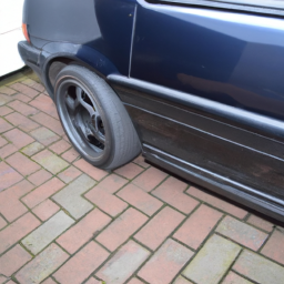
    Italy's Strange Answer To The Golf GTI – Alfa Romeo 33 1.7 Green Cloverleaf The Alfa Romeo 33 was based on the great AlfaSud but somehow Alfa managed to make it worse than the model it replaced.

Below is a step-by-step guide with detailed descriptions of the tools needed for this process.

### Tools and Materials Needed:

– **Jack and Jack Stands**
– A hydraulic floor jack to lift the vehicle.
– Jack stands to securely support the vehicle once lifted.

– **Socket Set**
– A comprehensive socket set (including both metric and standard sizes) to remove bolts and nuts. Common sizes for alfa 33 may include 10mm, 13mm, and 17mm sockets.

– **Ratchet Wrench**
– A ratchet wrench to attach to the sockets for ease of use.

– **Torque Wrench**
– A torque wrench to ensure that bolts are tightened to manufacturer specifications.

– **Pry Bar**
– A pry bar may be useful for removing stubborn components.

– **Ball Joint Separator**
– This tool helps in safely detaching the ball joint from the control arm without damaging other components.

– **Hammer**
– A rubber mallet or a dead blow hammer can assist in dislodging stuck parts.

– **Wrenches**
– Open-end and box-end wrenches in various sizes to accommodate different bolts.

– **Grease (if applicable)**
– To lubricate new bushings or joints as necessary.

– **Replacement Upper Control Arm**
– Ensure you have the correct part that matches your alfa 33 model year.

### Step-by-Step Replacement Process:

– **Preparation**
– Park the vehicle on a level surface and engage the parking brake.
– Gather all tools and materials for easy access during the process.

– **Lift the Vehicle**
– Use the hydraulic floor jack to lift the front of the vehicle.
– Place jack stands under the vehicle to ensure it is securely supported.

– **Remove the Wheel**
– Using the appropriate socket, remove the lug nuts and take off the front wheel to access the suspension components.

– **Locate the Upper Control Arm**
– Identify the upper control arm, which connects the wheel assembly to the chassis.

– **Remove the Ball Joint Nut**
– Using the appropriate socket and ratchet, remove the nut securing the ball joint at the top of the control arm.

– **Separate the Ball Joint**
– Use the ball joint separator to carefully detach the ball joint from the control arm. If necessary, tap it lightly with a hammer to loosen it.

– **Remove Control Arm Bolts**
– Locate and remove the bolts securing the upper control arm to the chassis. These may require a wrench or socket. Keep track of any washers or spacers.

– **Take Out the Old Control Arm**
– Carefully maneuver and remove the old control arm from the vehicle. Take note of how it is positioned for easier installation of the new one.

– **Install the New Upper Control Arm**
– Position the new control arm in place, aligning it with the chassis and the ball joint position.

– **Secure the Control Arm**
– Reinsert and hand-tighten the bolts to hold the control arm in place. Ensure that all spacers and washers are in their original positions.

– **Attach the Ball Joint**
– Align the ball joint with the steering knuckle and push it into place. Reattach the nut and tighten it to the manufacturer’s specifications using a torque wrench.

– **Final Tightening**
– Go through all boltsdownload ALFA 33 workshop manual and nuts, tightening them to the specified torque settings to ensure everything is secure.

– **Reattach the Wheel**
– Place the wheel back onto the hub and hand-tighten the lug nuts. Lower the vehicle and then use the torque wrench to tighten the lug nuts to the correct specification.

– **Lower the Vehicle**
– Carefully remove the jack stands and lower the vehicle completely to the ground.

– **Test Drive**
– Once the installation is complete, take the vehicle for a short test drive to ensure everything is functioning correctly. Listen for any unusual noises and check for proper alignment.

– **Check Alignment**
– It’s recommended to have the wheel alignment checked after replacing suspension components.

### Safety Tips:

– Always wear safety glasses and gloves when working on vehicles.
– Ensure the vehicle is securely supported before working underneath it.
– Consult the vehicle’s service manual for specific torque settings and procedures unique to your alfa 33 model.

By following these detailed steps and utilizing the right tools, you can successfully replace the upper control arm on an alfa 33.
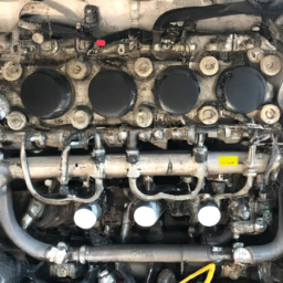
The timing chain is a crucial component in an internal combustion engine, responsible for synchronizing the rotation of the crankshaft and camshaft(s). This synchronization is vital for ensuring that the engine’s intake and exhaust valves open and close at the correct times during each cylinder’s intake and exhaust strokes. By maintaining this precise timing, the timing chain helps optimize engine performance, efficiency, and power output.

Typically made of metal links, the timing chain is designed to withstand the high levels of stress and heat produced within the engine. Unlike timing belts, which are made of rubber and require periodic replacement, timing chains are generally more durable and are often engineered to last for the lifetime of the vehicle. However, they can still experience wear over time due to factors such as oil contamination, inadequate lubrication, or improper tension.

Timing chains are usually housed within the engine and may be protected by a timing cover. They operate under high tension, maintained by tensioners and guides that help minimize slack and prevent the chain from skipping teeth on the sprockets. If a timing chain fails, it can lead to catastrophic engine damage, including bent valves, damaged pistons, or even complete engine failure. Regular maintenance, including oil changes and inspections, is essential to prolong the life of the timing chain and ensure reliable engine operation.

Download BMW 518I E28 Service Repair Manual 1985-1988 –

repairs
Replacing the timing chain on a BMW 518i E28 is a complex task that typically requires a good understanding of automotive mechanics. click here for more details on the download manual…..


    1987 BMW E28 seat operation

    BMW E28 Engine Compartment Fuse box diagram with location Details old model#shorts#bmw#fuse#box website link for India visitors ÷ https://sites.google.com/view/best-automobile-products/home website link for (United states) …

However, I’ll break it down into simple steps for you, assuming you have very little mechanical experience. Please keep in mind that this is a high-level overview and working on a car can be dangerous. If you’re not comfortable, it’s best to seek help from a professional mechanic.

### Tools and Materials Needed:
– Basic hand tools (wrenches, sockets, screwdrivers)
– Torque wrench
– Timing chain kit (includes chain, sprockets, guides, etc.)
– Oil and oil filter
– Gasket sealant
– Clean cloths

### steps to Replace the Timing Chain:

1. **Preparation:**
– Ensure the car is parked on a level surface and the engine is cool.
Disconnect the battery to prevent any electrical issues while you work.

2. **Remove the Engine Components:**
– **Remove the Air Intake:** Start by taking off the air filter housing and the intake hose to access the engine.
– **Remove the Valve Cover:** Take out the bolts securing the valve cover and carefully lift it off to expose the timing chain.
– **Remove other components:** Depending on access, you may need to remove additional components like the alternator, power steering pump, and any brackets blocking your path to the timing chain.

3. **Align the Engine:**
– Rotate the crankshaft (the large pulley at the bottom of the engine) using a wrench until the timing marks on the crankshaft and camshaft sprockets are aligned. This ensures the engine is at top dead center (TDC) for the number one cylinder.

4. **Remove the Old Timing Chain:**
– Remove the tensioner and guides. These parts hold the chain in place and maintain tension.
– Carefully take off the timing chain from the sprockets. Be cautious not to let any debris fall into the engine.

5. **Install the New Timing Chain:**
– Place the new timing chain over the sprockets, ensuring it follows the correct path (refer to a service manual for specific routing).
– Reinstall the tensioner and guides to secure the new chain in place.

6. **Reassemble the Engine:**
– Replace the valve cover with a new gasket or sealant to ensure a good seal.
– Reinstall any other components you took off earlier, such as the air intake and accessories.
– Double-check that all bolts and components are securely fastened.

7. **Refill Engine Oil:**
– Replace the oil filter and refill the engine with new oil. This is important because the timing chain operates in an oil-lubricated environment.

8. **Reconnect the Battery:**
– Once everything is back in place, reconnect the battery.

9. **Start the Engine:**
– Start the enginedownload BMW 518I E28 workshop manual and listen for any unusual noises. It should run smoothly if everything was done correctly.

10. **Final Checks:**
– After running the engine for a few minutes, check for any leaks around the valve cover and other components you removed.

### important Tips:
– Always refer to a service manual specific to the BMW 518i E28 for detailed diagrams and specifications.
– If at any point you feel unsure, it’s wise to consult with a more experienced mechanic or a professional shop.
– Make sure to work in a clean environment to avoid any dirt or debris getting into the engine.

### Safety Precautions:
– Use safety glasses to protect your eyes.
– Ensure the car is securely supported on jack stands if you need to lift it.
– Keep your work area organized to avoid losing small parts.

This task can be quite involved, and it’s important to proceed carefully and methodically. Good luck!
A wiper blade is an essential component of a vehicle’s windshield wiper system, designed to provide clear visibility for the driver by removing rain, snow, dirt, and debris from the windshield. Typically made of a rubber or silicone material, the wiper blade consists of a long, flat strip that is attached to a metal or plastic frame. The frame is connected to the wiper arm, which is powered by an electric motor to move the blade across the windshield in a back-and-forth motion.

Wiper blades come in various sizes and shapes to fit different vehicle models, and they are often categorized into two main types: traditional frame-style blades and more modern beam blades. The traditional blades feature a metal frame that holds the rubber strip, while beam blades offer a sleeker design without an external frame, allowing for better contact with the windshield surface.

Regular maintenance and timely replacement of wiper blades are crucial for optimal performance. Worn or damaged blades can lead to streaking, skipping, or even scratching the windshield, which compromises driver visibility and safety. Most manufacturers recommend changing wiper blades every six to twelve months, depending on the climate and usage conditions. Overall, wiper blades play a vital role in ensuring a safe driving experience, especially in adverse weather conditions.

Download HYUNDAI TERRACAN J3 DELPHI COMMON RAIL Diesel Engine Service Repair Manual –

buy
Replacing a gearbox synchronizer on a Hyundai Terracan J3 with a Delphi common rail engine involves several steps. click here for more details on the download manual…..


    DELPHI INJECTOR PULL OUT FROM HYUNDAI TERRACAN INJECTOR PULLER from CARBONZAPP.

    Hyundai Terracan 2.9 problems 1120 rail pressure Valve IMV fuel pressure hyundai terracan 2.9 crdi problems 1120 rail pressure control valve IMV 1120 rail pressure control valve IMV under the lower …

Here’s a reverse order explanation of the process:

### 1. **Reassemble the Gearbox**
– **Install the Gearbox Cover**: Secure the gearbox cover back onto the gearbox casing using the appropriate bolts.
– **Reconnect Gear Linkage**: Attach the gear linkage to the gearbox, ensuring it is properly aligned.
– **Install the drive Shafts**: Reinstall the drive shafts, ensuring they are secured and properly fitted into the differential.

### 2. **Refill Transmission Fluid**
– **Add Gear Oil**: Refill the gearbox with the correct type and amount of gear oil as specified in the vehicle’s service manual.

### 3. **Install the Gearbox**
– **Position the Gearbox**: Carefully lift the gearbox into place on the engine, ensuring alignment with the engine mounts and transmission bell housing.
– **Secure the Gearbox**: Use the bolts to secure the gearbox to the engine block, tightening them to the manufacturer’s specifications.

### 4. **Remove the Old Synchronizer**
– **Extract the Old Synchronizer**: Once the gearbox is opened, carefully remove the old synchronizer rings and the associated components from the gearbox.

### 5. **Disassemble the Gearbox**
– **Remove the Gearbox from the Vehicle**: Disconnect any necessary components (e.g., exhaust, crossmember) and lower the gearbox from the vehicle.
– **Remove the Input and output Shafts**: Take out the input and output shafts of the gearbox to access the synchronizer assembly.

### 6. **Gain Access to the Synchronizer Assembly**
– **Remove the Gear Selector Forks**: Take out the gear selector forks to gain access to the synchronizer.
– **Detach the Shift Mechanism**: remove any shift mechanisms or rods that may obstruct access to the synchronizer.

### 7. **Prepare for Replacement**
– **Gather Tools and Parts**: Ensure you have all necessary tools (sockets, wrenches, etc.) and the new synchronizer rings or assembly ready for installation.
– **Clean Components**: Clean all components and inspect them for wear or damage before reassembly.

### 8. **Safety Precautions**
– **Disconnect the Battery**: Always disconnect the vehicle’s battery before starting work on the electrical or mechanical systems.
– **Lift the vehicle Safely**: Use jack sdownload HYUNDAI TERRACAN J3 DELPHI COMMON RAIL Engine workshop manualtands or a lift to safely elevate the vehicle for easier access.

### Important Notes:
– Always consult the vehicle’s service manual for specific torque specifications and procedures.
– Be cautious of the gearbox’s weight and handle it carefully to avoid injury or damage.
– Ensure that all seals and gaskets are replaced as needed to prevent leaks.

This reverse order explanation helps in visualizing the entire process from completion to the start, aiding in Understanding the steps involved in replacing a gearbox synchronizer.
The steering wheel is a crucial component in the operation and control of a vehicle, serving as the primary interface between the driver and the vehicle’s steering mechanism. Typically circular in shape, the steering wheel allows drivers to maneuver the vehicle by turning it left or right, which directly influences the direction of the front wheels. This element is designed ergonomically to fit comfortably in the driver’s hands, enabling precise control and feedback during driving.

Made from a variety of materials, including plastic, leather, and sometimes wood or aluminum, steering wheels can vary significantly in design and functionality. many modern steering wheels are equipped with additional features such as integrated controls for audio systems, cruise control, and even hands-free communication, allowing drivers to operate various systems without taking their hands off the wheel. Additionally, some steering wheels come with adjustable features, such as tilt and telescoping capabilities, to accommodate drivers of different sizes and preferences.

The steering wheel is not only functional but also contributes to the overall aesthetic of the vehicle’s interior. It often reflects the brand’s design language and can enhance the driving experience through its tactile feedback. With advancements in technology, steering wheels are increasingly incorporating features like heating, cooling, and adaptive response, enhancing comfort and control for drivers in various driving conditions. Overall, the steering wheel is an essential component that combines functionality, safety, and style in the automotive world.

Download CITROEN DISPATCH 1.9D 2005 Service Repair Manual –

discount
Performing an exhaust repair on a Citroën Dispatch 1.9D involves several steps, which I will outline in reverse order for clarity. click here for more details on the download manual…..


    Citroen Peugeot Fiat Dispatch Jumpy Expert Scudo Micro Camper Conversion – [14] Alarm wiring Talk

    How To Remove Peugeot Partner/ Citroen Berling Front Shock Absorber

Note that working on the exhaust system can be hazardous, so ensure you have the appropriate safety gear and tools. Here’s how to do it in reverse order:

### 6. Reinstall Underbody Shields
– If you removed any underbody shields or covers, reattach them securely.

### 5. Tighten All Connections
– Ensure all clamps, bolts, and connections are tightened to prevent leaks.
– Double-check the exhaust hangers to make sure they are properly positioned and secure.

### 4. Reconnect the Exhaust System
– If you replaced or repaired a section of the exhaust, align the new parts with the existing system.
– Use exhaust clamps to secure the joints. Ensure they are tight to prevent any exhaust leaks.

### 3. Replace or Repair the Exhaust Component
– If you found a damaged section of the exhaust (like the muffler or pipe), remove the old part.
– Install the new or repaired component. Ensure that it fits correctly and is aligned with the rest of the exhaust system.

### 2. Inspect the Exhaust System
– Before making repairs, inspect the entire exhaust system for rust, holes, or cracks. Pay special attention to joints and connections.
– Identify the specific area that needs repair or replacement.

### 1. Gather Tools and Materials
– Collect all necessary tools, including a jack and jack stands, wrenches, sockets, pliers, and possibly a cutting tool if you need to remove a section of the exhaust.
– Obtain replacement parts if needed (muffler, pipes, clamps, etc.).

### Safety Precautions
– Ensure the vehicle is parked on a flat surface and the engine is cool.
– Use safety glasses and gloves to protect yourself from debris or sharp edges.
– If working under the vehicle, use jack stands to ensure it is securely elevated.

By following these steps in reverse order, you can effectively carry out an exhaust repair on a Citroën Dispatch 1.9D. Make sure to consult a service manual specific to your vehicle for any additional instructions or specifications.
An exhaust flange is a critical component in the exhaust system of a vehicle, serving as the joining point between different sections of the exhaust piping. Typically made from durable materials like stainless steel, carbon steel, or aluminum, exhaust flanges are designed to withsdownload CITROEN DISPATCH 1.9D workshop manualtand High temperatures and corrosive environments that are characteristic of exhaust gases.

The primary function of an exhaust flange is to create a secure and leak-free connection between exhaust components, such as the exhaust manifold, catalytic converter, muffler, and pipe sections. This connection is often achieved through bolting, where the flange is equipped with holes that allow bolts to pass through and tighten the joint. Some flanges may feature a gasket or sealing surface to enhance the seal and prevent exhaust leaks, which can lead to reduced engine efficiency and increased emissions.

Exhaust flanges come in various shapes and sizes, depending on the specific design and requirements of the vehicle’s exhaust system. they may be flat, raised, or even designed with specific contours to fit particular exhaust configurations. In addition to their functional role, exhaust flanges also play a part in the overall assembly and disassembly of the exhaust system, making maintenance and repairs more straightforward. A well-maintained exhaust flange is essential for optimal engine performance, noise reduction, and compliance with emission standards.

Download 2007-2012 ISUZU D-MAX – COLORADO Service Repair Manual –

shop
Replacing the transmission output shaft on an Isuzu D-Max or Colorado requires a good understanding of automotive mechanics, as well as the right tools and safety precautions. click here for more details on the download manual…..


    chevrolet colorado my17 vs isuzu d-max 2020 (คลิป 1) #NoBlackSmoke💨

    ISUZU D-MAX / COLORADO TRANSMISSION OIL COOLER INSTALL, INSTALLATION A TRANSMISSION OIL COOLER TO A FRIENDS 2018 2WD DMAX , ASWELL AS HOW TO CHECK THE …

Below is a detailed guide outlining the steps and components involved in the replacement process. Please ensure you have the necessary service manual for your specific model year, as details can vary.

### Tools and materials Needed:
– **Tools:**
– Socket set (metric)
– Wrench set (metric)
– Torque wrench
– Screwdrivers (flat and Phillips)
– Pliers
pry bar
– Hammer
– Jack and jack stands
– Transmission jack (optional but recommended)
– Seal puller
– Pick tool or small screwdriver

– **Materials:**
– New output shaft
– New output shaft seal
– Transmission fluid (as specified in your service manual)
– Thread locker (if required)
– Clean rags
– Safety goggles
– Gloves

### Step-by-Step Replacement Process:

1. **Preparation:**
– **Safety First:** Park the vehicle on a level surface and engage the parking brake. Wear safety goggles and gloves.
– **Disconnect the Battery:** Disconnect the negative terminal of the battery to prevent any electrical shorts.

2. **Lift the Vehicle:**
– Use a jack to lift the vehicle and securely place it on jack stands. Make sure it is stable before working underneath.

3. **Drain Transmission Fluid:**
– Place a drain pan under the transmission pan. Remove the drain plug (if available) or the transmission pan to drain the fluid completely. If you remove the pan, you may need to replace the gasket upon reinstallation.

4. **Remove Driveshaft:**
– **Mark the Driveshaft:** Use a marker to indicate the position of the driveshaft for easier reinstallation.
– **Unbolt the Driveshaft:** Use a socket to remove the bolts securing the driveshaft to the output flange. Support the driveshaft and slide it out of the transmission.

5. **Remove the Transmission Crossmember:**
– Unbolt the transmission crossmember using appropriate sockets and wrenches. Support the transmission with a transmission jack (or a regular jack) to prevent it from falling.

6. **Remove the Transmission Mounts:**
– Unbolt the transmission mounts from the transmission and the chassis.

7. **Lower the Transmission:**
– Carefully lower the transmission enough to access the output shaft. Be cautious not to damage any attached components.

8. **Remove the output Shaft:**
– **Locate the output Shaft Retaining Bolt:** Depending on your model, there might be a retaining bolt or nut securing the output shaft. Remove it using the appropriate socket.
– **Slide the output Shaft Out:** Gently pull the output shaft out of the transmission case. If it’s stuck, you may need to use a pry bar to carefully wiggle it free.

9. **Remove the output Shaft Seal:**
– Using a seal puller or a pick tool, carefully remove the output shaft seal from the transmission case. Be cautious not to damage the housing.

10. **Install New output Shaft:**
– **Lubricate the New Shaft:** Apply a small amount of transmission fluid to the new output shaft.
– **Insert the New output Shaft:** Slide the new output shaft into place, ensuring it fits snugly.

11. **Install New output Shaft Seal:**
– Use a seal installer tool or a similar object to press the new output shaft seal into place. Ensure it is seated evenlydownload ISUZU D MAX COLORADO workshop manual and flush with the transmission housing.

12. **Reassemble Transmission Components:**
– **Reinstall the output Shaft Retaining Bolt:** Torque it to the specifications in your service manual.
– **Reinstall Transmission Mounts:** bolt the transmission mounts back to the transmission and the chassis.
– **Reinstall the Transmission Crossmember:** Secure the crossmember to the transmission and the chassis.

13. **Reinstall Driveshaft:**
– Align the driveshaft with the marks you made earlier and secure it to the output flange with the bolts.

14. **Reconnect Transmission Fluid Lines (if applicable):**
– If you disconnected any fluid lines, reconnect them and ensure they are properly secured.

15. **Refill Transmission Fluid:**
– Remove the transmission dipstick (if equipped) and pour the recommended transmission fluid into the filler tube. Refer to your service manual for the correct fluid type and capacity.

16. **Reconnect the Battery:**
– Reconnect the negative terminal of the battery.

17. **Test the Vehicle:**
– Start the Engine and allow it to idle. Shift through all gears to ensure proper operation of the transmission. Check for any leaks around the output shaft and ensure the fluid level is correct.

### Final Thoughts:
Replacing the transmission output shaft is a complex task that requires attention to detail and mechanical skill. If at any point you feel unsure about the process, it may be best to consult a professional mechanic or refer to the vehicle’s service manual for more specific instructions. Always dispose of old transmission fluid and parts in accordance with local regulations.
A door hinge is a crucial mechanical component that facilitates the opening and closing of vehicle doors. It serves as the pivot point, allowing the door to swing outward or inward smoothly. Typically made from durable materials such as steel or reinforced plastic, door hinges are designed to withstand significant wear and tear, given that they are subjected to repeated movement and varying environmental conditions.

In automotive design, door hinges come in various configurations, including standard hinges, concealed hinges, and multi-link hinges. Standard hinges are the most common, allowing for a simple pivot motion. Concealed hinges, on the other hand, are designed to be hidden from view when the door is closed, providing a sleeker appearance. Multi-link hinges offer additional functionality, allowing doors to open wider or fold in a complex manner, which can be beneficial for vehicles with limited access space, such as sports cars or compact cars.

The installation and alignment of door hinges are vital for ensuring that the door closes securely and operates smoothly. Misalignment can lead to issues such as uneven gaps, difficulty in closing, or increased wear on the hinges themselves. In addition to their functional role, door hinges also contribute to the overall aesthetics of the vehicle, often being designed to complement the vehicle’s style. Proper maintenance of door hinges, including lubrication and regular inspection for rust or damage, is essential for prolonging their lifespan and ensuring optimal performance.

Download 2021 Volkswagen CrossGolf Download Service & Repair Manual –

buy
Certainly! click here for more details on the download manual…..


      #Volkswagen #CrossGolf#AutoMoto#Tuning#TopStars AutoMoto #Tuning #TopStars.

    Fuel system cleaning is an important maintenance task for your Volkswagen CrossGolf that helps keep the engine running smoothly. Here’s a simple, step-by-step guide to understand the process:

    ### What is Fuel System Cleaning?

    Fuel system cleaning is the process of removing dirt, deposits, and other contaminants from the fuel system. This includes the fuel injectors, fuel lines, and the combustion chamber. A clean fuel system improves performance, fuel efficiency, and reduces emissions.

    ### Why Clean the Fuel System?

    Over time, deposits can build up in the fuel system, which can lead to:
    – Poor engine performance
    – Decreased fuel efficiency
    rough idling or stalling
    – Increased emissions

    ### Tools and Materials Needed

    1. **Fuel System Cleaner**: A special cleaning solution designed to dissolve deposits.
    2. **Fuel Pump or Sprayer**: Depending on the method, you may need a way to introduce the cleaner into the fuel system.
    3. **Safety Gear**: Gloves and goggles for protection.
    4. **Basic Hand Tools**: Such as wrenches or screwdrivers, if needed.

    ### Steps to Clean the Fuel System

    1. **Preparation**:
    – Park your CrossGolf on a flat surface and turn off the engine.
    – Make sure the vehicle is in a well-ventilated area, as fuel vapors can be harmful.

    2. **Access the Fuel System**:
    you may need to access the fuel rail or fuel injectors, which are usually located on top of the engine. Consult your owner’s manual for details on how to do this safely.

    3. **Introduce the Fuel System Cleaner**:
    – **Direct Method**: If your cleaner comes with a tool, connect it to the fuel rail or follow the instructions provided by the cleaner’s manufacturer.
    – **Indirect Method**: Alternatively, you can add the fuel system cleaner directly to your fuel tank. Check the instructions for the correct ratio based on your tank size.

    4. **Run the Engine**:
    – Start the engine and let it run for a while (about 15-30 minutes). This allows the cleaner to circulate through the fuel system and clean the components.
    you may notice some changes in engine sound or performance during this time, which is normal.

    5. **Finish Up**:
    – After the cleaning process, you can refuel your CrossGolf to ensure that any remaining cleaner is diluteddownload Volkswagen CrossGolf workshop manual and burned off.
    – Check for any leaks or issues around the fuel system area before closing everything up.

    6. **Regular Maintenance**:
    – Consider cleaning the fuel system every 5,000 to 10,000 miles, or as recommended by your mechanic, to keep your engine in top condition.

    ### Important Tips

    – Always follow the manufacturer’s instructions for the specific cleaner you are using.
    – If you’re unsure or uncomfortable with any part of the process, it’s best to seek help from a professional mechanic.
    – Regularly check and replace your fuel filter as part of your vehicle’s maintenance routine.

    By following these steps, you can help ensure that your Volkswagen CrossGolf runs efficiently and stays in great shape!
    A door hinge is a crucial mechanical component that facilitates the opening and closing of a vehicle’s doors. It serves as a pivot point, allowing the door to swing outward or inward while maintaining a secure attachment to the vehicle’s body. Typically made from durable materials such as steel or aluminum, door hinges are designed to withstand the stresses of frequent use and the weight of the door itself.

    The design of a door hinge consists of two primary plates, known as leaves, which are connected by a central pin. One leaf is attached to the door, while the other is mounted to the vehicle’s frame. This configuration enables smooth movement while providing stability. There are various types of hinges utilized in automotive applications, including conventional hinges, which are commonly found on most passenger vehicles, and specialized hinges, such as those used for sliding or gullwing doors.

    In addition to their functional role, door hinges can also contribute to the aesthetic appeal of a vehicle. properly functioning hinges ensure that doors align correctly with the body, preventing issues like misalignment, rattling, or difficulty in closing. Over time, door hinges can experience wear and tear, leading to squeaking sounds or reduced functionality, necessitating maintenance or replacement to ensure optimal performance. Overall, door hinges are integral to both the practicality and usability of a vehicle, playing an essential role in the overall user experience.

    Download Kia Optima 2006 Workshop Repair Service Manual –

    diy
    Rebuilding a transmission can be a complex process, especially if you have little mechanical experience. click here for more details on the download manual…..


      Kia Optima 4th generation 2015 to 2020 common problems, defects, issues, recalls and complaints. Kia Optima 4th generation 2015 to 2020 common problems, defects, issues, recalls and complaints. About Us …

      Kia Optima Muffler Delete

    However, I can provide a simplified overview of the steps involved in rebuilding a transmission on a Kia Optima. Please remember that this is a general guide, and it’s highly recommended to consult a professional mechanic or refer to a specific repair manual for your vehicle model. Also, working on a vehicle can be dangerous, so take appropriate safety precautions.

    ### Basic Tools and Materials You Might Need:
    – Basic hand tools (wrenches, sockets, screwdrivers)
    – Torque wrench
    – Pliers
    – Transmission rebuild kit (includes gaskets, seals, clutches, etc.)
    – Fluid for the transmission
    – Cleaning supplies (degreaser, rags)
    – Safety gear (gloves, goggles)

    ### Steps to Rebuild a Kia Optima Transmission:

    1. **Preparation:**
    – **Safety First:** Make sure the car is parked on a level surface, turn off the engine, and disconnect the battery to prevent any electrical issues.
    – **Gather Tools:** Collect all necessary tools and materials.

    2. **Remove the Transmission:**
    – **Lift the Car:** Use a jack and jack stands to lift the car securely.
    – **Remove Underbody Components:** Depending on the model, you might need to take off the exhaust system or other parts to access the transmission.
    – **Disconnect Components:** Disconnect the driveshaft, electrical connectors, and any other components attached to the transmission (like the shift linkage).
    – **Unbolt the Transmission:** Carefully remove the bolts that hold the transmission to the engine block and gently slide it out.

    3. **Disassemble the Transmission:**
    – **Clean the Exterior:** Before opening it, clean the outside of the transmission to prevent dirt from entering.
    – **Remove the Cover:** Take off the transmission pan and filter, allowing the old fluid to drain out.
    – **Take Photos:** As you disassemble, take photos to remember where everything goes.
    – **Remove Internal Components:** Carefully take out gears, clutches, and other internal parts. Be mindful of the order and orientation for reassembly.

    4. **Inspect Components:**
    – **Check for Wear:** Look for any worn or damaged parts. This includes gears, clutches, and seals. Replace any damaged components with parts from your rebuild kit.
    – **Clean Parts:** Use a degreaser to clean all parts thoroughly.

    5. **Reassemble the Transmission:**
    – **Install New Parts:** Start putting the transmission back together. Install new clutches, seals, and gaskets as per your rebuild kit instructions.
    – **Follow Photos or Manual:** Use your photos or a repair manual to ensure everything is put back in the correct order.

    6. **Reinstall the Transmission:**
    – **Position the Transmission:** Carefully lift the transmission back into place and align it with the engine.
    – **Bolt it Back Together:** Reattach all boltsdownload Kia Optima workshop manual and components you previously removed.
    – **Reconnect Components:** Reattach the driveshaft, electrical connectors, and any other parts.

    7. **Refill Transmission Fluid:**
    – **Add New Fluid:** Use the appropriate transmission fluid for your Kia Optima. Fill it through the dipstick tube or designated fill port, as specified in the manual.

    8. **Test Drive:**
    – **Reconnect the Battery:** Once everything is reassembled, reconnect the battery.
    – **Start the Engine:** Let it run for a few moments and check for any leaks.
    – **Take a Test Drive:** go for a short drive to ensure the transmission is operating smoothly.

    ### Final Notes:
    – **Take your Time:** Rebuilding a transmission is a detailed process that requires patience. Don’t rush.
    – **Consult References:** Use a repair manual specific to your Kia Optima for detailed instructions and diagrams.
    – **Get Help if Needed:** If at any point you feel uncertain, it’s best to consult a professional mechanic.

    This guide is a basic overview and should not replace professional advice or detailed manuals. Working on a transmission can be complicated and may require specialized knowledge.
    The wheel is a fundamental component of any vehicle, crucial for its mobility and functionality. It is a circular object that rotates around an axle, allowing the vehicle to move along the ground. Traditionally made from materials like wood, metal, or rubber, modern wheels are often constructed from lightweight alloys or composite materials to enhance performance and fuel efficiency.

    A wheel typically consists of several parts, including the rim, which is the outer edge that holds the tire; the hub, which is the central part that attaches to the axle; and spokes or solid structures that connect the rim to the hub, providing strength and stability. The tire, mounted on the rim, is essential for traction, handling, and comfort, as it absorbs shocks from the road surface.

    Wheels serve multiple functions beyond just supporting the vehicle’s weight. They enable steering, as the front wheels pivot to guide the car in different directions. Additionally, the design and size of wheels can significantly influence a vehicle’s performance characteristics, such as acceleration, braking, and cornering. Larger wheels may enhance aesthetics and improve handling on paved roads, while smaller wheels might be better suited for off-road applications.

    In summary, wheels are vital to a vehicle’s operation, impacting safety, efficiency, and overall driving experience. Their design and construction continue to evolve, reflecting advances in technology and engineering.

    Download Cummins ISB CM2150 Engine Workshop Repair Service Manual –

    australia
    Conducting a transmission fluid pressure test on a Cummins ISB CM2150 engine involves checking the pressure of the transmission fluid to ensure that it is operating correctly. click here for more details on the download manual…..


      2009 Cummins ISB 6.7 Diesel Engine for sale, OEM REMAN, CM2150 (OEM REMAN/ USED TESTED/ FULLY INPSPECTED) 2009 Cummins ISB 6.7 Diesel Engine (EPA07), Cummins Reman Serial …

      EGR Quick Fix 2 – Cummins Don’t forget to Like and Subscribe! – https://goo.gl/XtV9CJ Check out Part 1 for more info – https://youtu.be/rj1KbDarFxQ Some …

    This can help diagnose problems such as slipping gears or poor shifting. Below, I’ll explain how to perform this test in simple terms.

    ### Tools and Equipment Needed:
    1. **Pressure Gauge**: A hydraulic pressure gauge that can measure the transmission fluid pressure (usually between 0 to 300 psi).
    2. **Adapter Fitting**: This is needed to connect the pressure gauge to the transmission.
    3. **Wrench Set**: To remove and install fittings.
    4. **Safety Glasses**: To protect your eyes.
    5. **Shop Towels**: For cleaning up any spills.

    ### Safety Precautions:
    – Make sure the vehicle is parked on a flat surface.
    – Engage the parking brake.
    – Wear safety glasses to protect your eyes.
    – Ensure the engine is off before setting up.

    ### Steps to Perform a transmission Fluid Pressure Test:

    1. **Locate the transmission Test Port**:
    – Find the transmission on your vehicle. The ISB CM2150 engine is often found in heavy-duty trucks, so look underneath the vehicle.
    – Look for a test port or a pressure tap on the transmission. This is usually a small bolt or plug where you can connect the pressure gauge.

    2. **Prepare the Vehicle**:
    – Start the engine and let it warm up to operating temperature. This is important because fluid viscosity changes when it’s cold.
    – Ensure that the transmission is in “Park” (if automatic) or neutral (if manual).

    3. **Turn Off the Engine**:
    – Once the engine is warmed up, turn it off to connect the pressure gauge.

    4. **Remove the Test Port Plug**:
    – Use a wrench to carefully remove the test port plug. Be prepared for some fluid to leak out, so have your shop towels handy.
    – Make sure to note any washers or seals that may come off with the plug.

    5. **Install the Pressure Gauge**:
    – Take the pressure gauge and attach it to the test port. Ensure it is securely fastened to avoid leaks. If you have an adapter, use it as needed.

    6. **Start the Engine Again**:
    – Turn the engine back on. Make sure to monitor the gauge as you proceed.
    – Keep the vehicle in “Park” or “Neutral” and observe the pressure reading on the gauge.

    7. **Check the Pressure Reading**:
    – Refer to the manufacturer’s specifications for normal operating pressure for the Cummins ISB CM2150 engine’s transmission. Typically, it should be within a specific range.
    – If the pressure is too low or too high, it may indicate a problem with the transmission, such as a faulty pump or blockage.

    8. **Test in Different Gears**:
    – While monitoring the pressure, you may want to shift through different gears (if safe to do so)download Cummins ISB CM2150 Engine workshop manual 
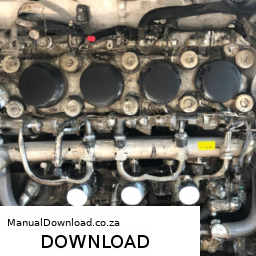
and observe how the pressure changes. This can help diagnose issues Related to shifting.

    9. **Turn Off the Engine and Remove the Gauge**:
    – Once you have your readings, turn off the engine again.
    – Carefully remove the pressure gauge and reinstall the test port plug securely.
    – Clean up any spilled fluid.

    10. **Dispose of Any Fluid Properly**:
    – If you’ve spilled any transmission fluid, clean it up and dispose of it according to your local regulations.

    ### Conclusion:
    By following these steps, you can perform a transmission fluid pressure test on a Cummins ISB CM2150 engine. Remember, if you find abnormal pressure readings, it’s best to consult with a professional mechanic who can further diagnose and repair any issues.
    The fuel tank is a crucial component of an internal combustion engine vehicle, serving as the storage unit for fuel, typically gasoline or diesel, that powers the engine. Located in various positions depending on the vehicle design—commonly at the rear or under the floor—the fuel tank is engineered to hold a significant volume of fuel while ensuring safety and efficiency.

    Made primarily from materials such as high-density polyethylene (HDPE) or metal, the tank is designed to withstand the corrosive nature of fuel and the varying pressures and temperatures experienced during operation. A well-designed fuel tank incorporates features such as baffles to minimize fuel slosh, which can affect vehicle handling, especially during sharp turns or sudden stops.

    The fuel tank is connected to the fuel system, including the fuel pump, which draws fuel from the tank and delivers it to the engine. It also contains a fuel gauge that provides the driver with information about the fuel level, allowing for better trip planning and fuel management. Additionally, modern fuel tanks are equipped with vapor recovery systems to minimize evaporative emissions, contributing to environmental protection.

    In summary, the fuel tank is not just a storage vessel; it plays a vital role in the overall performance, efficiency, and environmental impact of a vehicle, making it a key component in automotive engineering.

    Download 1995 BMW 323 (E36) 3 Series Compact OEM Download Service & Repair Manual Software –

    online
    Replacing the gearbox planetary gears on a BMW 323 E36 Compact involves several detailed steps. click here for more details on the download manual…..


      BMW E39/E46 Manual Shifter Bushing Refresh with Turner Motorsports Kit

      BMW E36 3-Series Buying Guide – 90s Icon Turned Classic Investment! WIN With Lancaster Insurance: https://bit.ly/3BUKBKb The third-generation ‘E36’ BMW 3-Series was launched in 1991 and took …

    Here’s a reverse order summary of the process:

    ### Reverse Order Steps for Gearbox Planetary Gear Replacement:

    1. **Reinstall the Gearbox**: Secure the gearbox back into the vehicle, ensuring all bolts are tightened to the manufacturer’s specifications.

    2. **Reconnect Electrical Connections**: Attach any electrical connectors related to the gearbox, including sensors and wiring harnesses.

    3. **Reconnect the Driveshaft**: Reattach the driveshaft to the gearbox, ensuring it is properly aligned and secured with the appropriate bolts.

    4. **Fill Transmission Fluid**: Refill the gearbox with the correct type and amount of transmission fluid as specified in the BMW service manual.

    5. **Reinstall the Gearbox Mounts**: Secure the gearbox mounts to the vehicle’s chassis, ensuring everything is tight and secure.

    6. **Reattach the Exhaust (if applicable)**: If any part of the exhaust system was removed for access, reinstall it now.

    7. **Remove the Old Gearbox**: If not already done, detach the gearbox from the engine by removing the bolts connecting it to the engine block.

    8. **Drain Transmission Fluid**: Drain the existing fluid from the gearbox to prevent spills during the disassembly process.

    9. **Remove the Transmission Pan**: If applicable, unbolt and remove the transmission pan to access the internal components of the gearbox.

    10. **Take Out the Valve Body**: Carefully unbolt and remove the valve body to gain access to the planetary gears.

    11. **Remove the Planetary Gear Assembly**: Take out the planetary gear set by unbolting it from the gearbox housing.

    12. **Inspect and Replace Gears**: Check the planetary gears for wear and damage, and replace them with new OEM parts as necessary.

    13. **Clean the Gearbox Components**: Clean any gasket surfaces and components that will be reused to ensure a proper seal and function.

    14. **Reassemble the Gearbox**: Reassemble the gearbox in reverse order, ensuring all components are properly seated and torqued to specifications.

    15. **Prepare the Vehicle**: Lift the vehicle securely and remove any underbody panels or covers needed to access the gearbox.

    ### Additional Tips:
    – Always refer to the specific service manual for your BMW 323 E36 for detailed specificationsdownload BMW 323 E36 3 Compact OEM workshop manual and torque settings.
    – Ensure you have all necessary tools and parts before beginning the replacement process.
    – Consider the use of a transmission jack to assist with the removal and installation of the gearbox.
    – Work in a clean environment to prevent contamination of gearbox components.

    This reverse order summary provides a high-level overview of the steps involved in replacing the planetary gears in the gearbox of a BMW 323 E36 Compact. Always consult a professional or detailed service manual for comprehensive guidance.
    A torque converter is a crucial component in an automatic transmission system, primarily serving to transfer power from the engine to the transmission while also allowing for a smooth transition of power during vehicle operation. It functions by using a fluid coupling mechanism that transmits torque from the engine to the transmission, allowing for a seamless connection without the need for a manual clutch.

    The torque converter consists of three main components: the impeller, turbine, and stator. The impeller is connected to the engine’s flywheel and spins with the engine’s RPM. As the impeller rotates, it draws in transmission fluid, which is then directed toward the turbine. The turbine, connected to the transmission, captures the fluid’s energy and converts it back into rotational motion, thereby driving the vehicle. The stator, located between the impeller and turbine, redirects the fluid returning from the turbine, enhancing efficiency and increasing torque at low speeds.

    One of the key advantages of a torque converter is its ability to multiply torque, particularly during acceleration, making it easier for the vehicle to start moving from a complete stop. Additionally, it allows for smooth gear shifting, as it can adjust the power delivery based on driving conditions without the driver needing to manually disengage or engage gears. Overall, the torque converter plays a vital role in enhancing performance, fuel efficiency, and driving comfort in vehicles equipped with automatic transmissions.

    Download 2006 Mercedes-Benz R-Class R350 (W251) OEM Download Service & Repair Manual Software –

    service
    Replacing the shock mounts on a Mercedes-Benz R-Class R350 (W251) involves several steps and requires specific tools and components. click here for more details on the download manual…..


      2007 Mercedes R350 Headlight / Head lamp RH GOOD SHAPE 251TYPE – mbiparts.com Used OEM Merced… … Buy parts for 2007 Mercedes R350! Call us at 1-916-638-6748 for a free quote! http://mbiparts.com 2007 Mercedes R350 …

      2007 Mercedes R350 Engine / Motor RUNS AND DRIVES 251TYPE – mbiparts.com Used OEM Mercedes P… … Buy parts for 2007 Mercedes R350! Call us at 1-916-638-6748 for a free quote! http://mbiparts.com 2007 Mercedes R350 Engine …

    Below is a detailed guide to performing this task.

    ### Tools and Materials Required

    1. **Tools:**
    – Socket set (metric)
    – Wrenches (metric)
    – Torque wrench
    – Floor jack
    – Jack stands
    – Suspension spring compressor (if necessary)
    – Impact wrench (optional but recommended)
    screwdrivers (flat and Phillips)
    – Pliers
    – Hammer
    – Rubber mallet
    – Safety goggles and gloves

    2. **Materials:**
    – New shock mounts (OEM or aftermarket)
    – New shock absorbers (if replacing)
    – New hardware (if necessary)
    – Grease (optional, for mounting surfaces)

    ### Components of the Shock Mount

    – **Shock Absorber:** The part that dampens the impact of the road and controls the rebound of the suspension.
    – **Shock Mount (Upper):** The component that connects the shock absorber to the vehicle’s body, often including a rubber bushing to absorb vibrations.
    – **Nut/Bolt Assembly:** Fasteners that secure the shock mount to the body and the shock absorber.
    – **Dust Boot:** A protective cover that prevents dirt and debris from entering the shock absorber.
    – **Spring Seat:** sometimes integrated with the shock mount, it holds the coil spring in place.

    ### Steps for Shock Mount Replacement

    1. **Safety First:**
    – Ensure the vehicle is on a flat surface.
    – Wear safety goggles and gloves.

    2. **Lift the Vehicle:**
    – Use a floor jack to lift the vehicle at the designated lifting points.
    – Secure the vehicle with jack stands to ensure stability.

    3. **Remove the Wheel:**
    – Use a socket wrench to remove the lug nuts and take off the wheel. This will give you access to the shock assembly.

    4. **Inspect Shock Absorbers:**
    – Check for any signs of leakage or damage. If the shock absorbers are worn, consider replacing them at this time.

    5. **Remove Shock Absorber:**
    – Locate the bolts securing the shock absorber at the bottom (usually at the lower control arm) and the top (attached to the body).
    – Use an impact wrench or socket wrench to remove these bolts. It may require holding the shock shaft with a wrench to prevent it from spinning.
    – Carefully pull the shock absorber out from the bottom.

    6. **Remove Old Shock Mount:**
    – At the top of the shock absorber, the shock mount is typically secured with a nut. Use the appropriate socket to remove this nut.
    – Once the nut is removed, separate the shock mount from the shock absorber. You may need to tap it gently with a hammer or use a rubber mallet If it’s stuck.

    7. **Install New Shock Mount:**
    – Take the new shock mount and position it onto the top of the new or existing shock absorber.
    – Secure it with the nut, making sure it’s tight but do not overtighten at this stage.

    8. **Reinstall Shock Absorber:**
    – Insert the shock absorber back into its mounting position. Line up the bottom of the shock with the control arm and secure it with the bolts.
    – Torque the bolts to the manufacturer’s specifications (check the repair manual for specifics).

    9. **Reattach the Wheel:**
    – Place the wheel back ondownload Mercedes Benz R Class R350 W251 OEM workshop manual and hand-tighten the lug nuts.
    – Lower the vehicle back to the ground using the floor jack and then fully tighten the lug nuts in a criss-cross pattern.

    10. **Test the Installation:**
    – Before driving, press down on the vehicle to ensure the suspension compresses and rebounds appropriately.
    – Check for any unusual noises or movements.

    11. **Repeat for Other Side (if necessary):**
    If you are replacing the shock mounts on both sides, repeat the above steps for the other side.

    ### Important Tips

    – Always refer to the vehicle’s service manual for specific torque specifications and detailed diagrams.
    If the vehicle has a self-leveling suspension, ensure you understand the system before proceeding with the replacement.
    – Consider replacing the shock absorbers If you notice any signs of wear or If the vehicle has high mileage.

    ### Conclusion

    Replacing the shock mounts on a Mercedes-Benz R-Class R350 (W251) can significantly improve ride quality and handling. Always take the necessary precautions and, If unsure, consult a professional mechanic to perform the replacement for you.
    The steering box, also known as the steering gear, is a crucial component of a vehicle’s steering system. It is responsible for translating the rotational motion of the steering wheel into the lateral movement of the vehicle’s wheels. Essentially, it serves as the intermediary that allows the driver to control the direction of the vehicle effectively.

    There are several types of steering boxes, including recirculating ball, rack and pinion, and worm gear systems. Each type has its own mechanism for achieving this motion, but they all share the common purpose of enabling precise steering control. The recirculating ball steering box uses a series of ball bearings to reduce friction and improve steering feel, making it common in older vehicles and trucks. On the other hand, the rack and pinion system, which has become more prevalent in modern vehicles, utilizes a gear mechanism that translates the rotary motion of the steering wheel into the linear motion needed to turn the wheels.

    The steering box is typically mounted to the vehicle’s chassis and is connected to the steering column, which transmits the driver’s input. It also connects to the tie rods that link to the wheels, allowing for direct control over the vehicle’s direction. Proper functioning of the steering box is essential for safe driving, as any wear or malfunction can lead to poor steering response, reduced handling, and even loss of control of the vehicle. Regular maintenance and inspection are vital to ensure its longevity and reliability, contributing significantly to overall driving safety and comfort.