Download Tadano GR-700EX-1 Rough Terrain Crane Service Manual –

repair manual
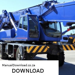
Replacing the strut on a Tadano GR 700EX 1 Rough Terrain Crane involves multiple steps, and it’s crucial to follow them carefully to ensure safety and proper function. click here for more details on the download manual…..


    Tadano (4.9 ton) Rough Terrain Crane GR130N-1 (2014) For Sale Tadano Rough Terrain Crane Model: GR130N-1 Year: 2014 S/N: FD27xx Capacity: 4.9 ton Working hours: 9000 hrs Mileage: …

    [ENGLISH] Tutorial For A 75 – 100 Ton Tadano Crane Setups and Safety Welcome to BADBOY Cranes. We are making it our mission to bring y’all English tutorials to operate safely in so many cranes.

Below is a reverse order guide to help you understand the process:

### 8. Reassemble and Test
– **Reconnect Electrical Connections**: If any electrical connections were disconnected, ensure they are properly reconnected.
– **Check Fluid Levels**: Verify that hydraulic fluid levels are adequate and top off if necessary.
– **Lower the Crane**: Gradually lower the crane back to the ground.
– **Test the Crane**: Perform a functionality test to ensure everything operates correctly before full operation.

### 7. final Adjustments
– **Tighten All Bolts**: Go through and make sure all bolts and fasteners are tightened to the manufacturer’s specifications.
– **Inspect Alignment**: Ensure the new strut is aligned properly with all components.

### 6. Install the New Strut
– **Position the New Strut**: Carefully place the new strut in position.
– **Secure the Strut**: Fasten the strut using the appropriate bolts or fasteners, ensuring they are torqued to the specified settings.

### 5. Remove the Old Strut
– **Detach from Mounting Points**: Unscrew and remove the bolts that attach the old strut to the crane.
– **Extract the Old Strut**: Carefully pull the old strut out of its position.

### 4. Prepare for Replacement
– **Support the Crane**: Use jack stands or other supports to ensure the crane is stable and secure during the replacement process.
– **Raise the Crane**: Use the crane’s hydraulic system to lift it to a safe working height, ensuring that it is stable.

### 3. Gather tools and Parts
– **Collect Tools**: Obtain necessary tools such as wrenches, sockets, and torque wrench.
– **Acquire Replacement Strut**: Ensure you have the correct replacement strut for the Tadano GR 700EX 1.

### 2. Safety Precautions
– **Wear Personal Protective Equipment (PPE)**: Use gloves, goggles, and other necessary PPE.
– **Ensure Crane is in safe Condition**: Perform a pre-check of the crane to ensure it is in a safe condition to work on.

### 1. Review Manufacturer Guidelines
– **Consult Manual**: Review the service manual for the Tadano GR 700EX 1 for specific Instructionsdownload Tadano GR 700EX 1 Rough Terrain Crane workshop manual 
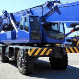
and torque specifications related to strut replacement.

### Conclusion
Following this reverse order guide should help ensure that you can successfully replace the strut on a Tadano GR 700EX 1 Rough Terrain Crane. Always prioritize safety, and consult the manufacturer’s manual for detailed Instructions and specifications.
The valve cover gasket is a crucial component in an internal combustion engine, primarily serving as a seal between the valve cover and the cylinder head. Made from materials such as rubber, silicone, or cork, the gasket plays a vital role in preventing oil leaks from the engine. The valve cover itself houses the camshaft, valves, and other related components, and is essential for protecting these parts from dirt, debris, and other contaminants that could interfere with their operation.

When the engine is running, it generates heat, and the materials used in the valve cover gasket need to withstand these varying temperatures without degrading. Over time, exposure to high temperatures and engine vibrations can cause the gasket to become brittle, crack, or warp, leading to leaks. This not only results in oil loss but can also lead to serious engine damage if the oil level drops too low or if the leaking oil comes into contact with hot engine components, potentially causing fires or other hazardous conditions.

Replacing a worn or damaged valve cover gasket is a common maintenance task that can help maintain engine performance and longevity. Signs that a valve cover gasket may need replacing include oil spots under the vehicle, a burning oil smell, or visible oil around the valve cover. Regular inspection and timely replacement can prevent more significant issues, making the valve cover gasket an essential element in an engine’s health and efficiency.

Download Renault Scenic 1995-2002 Service Repair Manual –

sale
Replacing the fuel pump on a Renault Scenic can be a complex task, but with the right tools and steps, it can be accomplished. click here for more details on the download manual…..


    2006 RENAULT SCENIC DYNAMIQUE VVT A BLACK AUTOMATIC TRANSMISSION Manufacturer: RENAULT Model: SCENIC DYNAMIQUE VVT A Type: MPV Doors: 5 DOOR MPV Colour: BLACK Year: 2006 Reg.

    "DIY Car Maintenance: Renault Megan Scenic – Replace Spark Plugs, Air Filter, and More! Welcome to my channel! In this tutorial, we’ll walk you through a step-by-step guide on how to perform a regular service on your …

Here’s a detailed guide:

### Tools and Materials Required:

– **Safety Glasses**: Protects your eyes from fuel splashes and debris.
– **Gloves**: To protect your hands from fuel and sharp edges.
– **Socket Set**: Various sizes of sockets to remove bolts and screws.
– **Ratchet Wrench**: For easier torque application when removing or tightening bolts.
– **Flathead Screwdriver**: useful for prying clips and accessing certain components.
– **Phillips Head Screwdriver**: For screws that may hold components in place.
– **Pliers**: For removing clamps or securing hoses.
– **Fuel Line Wrench**: Specialized tool for safely disconnecting fuel lines without damaging them.
– **Container**: To catch any residual fuel when disconnecting lines.
– **Shop Towels/Rags**: For cleaning up spills and wiping hands.
– **Replacement Fuel Pump**: Ensure it is compatible with your Renault Scenic model.
– **New Fuel Filter**: Recommended to replace when changing the fuel pump.
– **Torque Wrench**: To ensure bolts are tightened to the manufacturer’s specifications.

### Steps for Fuel Pump Replacement:

– **Safety First**:
– Park the vehicle on a flat surface and engage the parking brake.
– Wear safety glasses and gloves to protect yourself from fuel and debris.

– **Relieve Fuel Pressure**:
– Locate the fuel pump fuse in the fuse box and remove it.
– Start the engine and let it run until it stalls to relieve pressure in the fuel lines.
– Turn off the ignition and disconnect the negative battery terminal to prevent electrical sparks.

– **Access the Fuel Pump**:
– Depending on the model, the fuel pump may be located in the fuel tank or under the rear seat.
– If in the tank, you may need to remove the rear seat or trunk cover to access the pump access panel.
– Remove any screws or clips securing the access panel and lift it off.

– **Disconnect Fuel Lines**:
– Use the fuel line wrench to carefully disconnect the fuel lines from the pump.
– Place a container underneath to catch any residual fuel that may spill.
– Be cautious not to damage the fuel lines or connectors during this process.

– **Remove the Fuel Pump**:
– Disconnect any electrical connectors attached to the fuel pump.
– If applicable, remove any retaining ring or bolts that hold the pump in place.
– Carefully lift the fuel pump assembly out of the tank, taking care not to bend or damage the float arm or other components.

– **Install the New Fuel Pump**:
– Compare the new pump with the old one to ensure compatibility.
– Install the new pump into the tank, ensuring it is seated properly.
– Reattach any retaining rings or bolts to secure the pump in place.

– **Reconnect Fuel Linesdownload Renault Scenic workshop manual and Electrical Connectors**:
– Reconnect the fuel lines to the new pump, ensuring they are secured and leak-free.
– Reattach any electrical connectors, ensuring they click into place.

– **Reinstall Access Panel**:
– Replace the access panel you removed earlier, securing it with screws or clips.

– **Reconnect the Battery**:
– Reconnect the negative battery terminal and ensure all connections are tight.

– **Test the System**:
– Replace the fuel pump fuse in the fuse box.
– Turn the ignition to the “on” position (without starting the engine) to prime the fuel system and check for leaks.
– If there are no leaks, start the engine and let it run for a few minutes to ensure the new pump is functioning correctly.

– **Dispose of Old Fuel Pump**:
– Dispose of the old fuel pump and any spilled fuel or materials according to local regulations.

### Final Tips:
– Always consult the vehicle’s service manual for specific instructions related to your model.
– If you’re unsure or uncomfortable performing the replacement, consider seeking professional help.
– Keep work areas clean and organized to avoid losing parts or tools.
A hubcap is a protective and decorative cover that is typically fitted over the wheel hub of a vehicle. It serves both functional and aesthetic purposes. Functionally, hubcaps help to protect the wheel’s lug nuts and the hub assembly from dirt, debris, and moisture, which can lead to corrosion and damage over time. By covering these components, hubcaps can help prolong the life of the wheel and maintain the vehicle’s performance.

Aesthetically, hubcaps enhance the overall appearance of the wheel and the vehicle itself. They come in various designs, sizes, and finishes, allowing car manufacturers to tailor the look of a vehicle to its intended style or market. Hubcaps can be made from a variety of materials, including plastic, aluminum, or steel, and they can be found in different colors and patterns, ranging from sleek and modern to classic and ornate.

While hubcaps have been a common feature on many vehicles, the rise of alloy wheels has changed their role in automotive design. In some cases, modern cars feature integrated designs where the hubcap is part of the wheel itself, while others may use full wheel covers that provide a similar protective function.

Overall, hubcaps play an essential role in vehicle maintenance and aesthetics, combining functionality with style to enhance the driving experience.

Download Dodge Charger LX 2006 Workshop Service Repair Manual –

repairs
Differential service on a Dodge Charger LX is crucial for maintaining the vehicle’s performance and handling. click here for more details on the download manual…..


    Twin Turbo Charger R/T 2014 Twin Turbo R/T Built by SNL Performance 5.7 Hemi with forged internals Twin Turbo kit by SNL Performance. Low boost 7 …

    Charger/challenger/300/ magnum srt8 6 piston brembo upgrade from 4 piston Upgraded to 6 piston brembo from the 4 piston.

The differential allows for the outside wheels to rotate faster than the inside wheels during turns, which is essential for stability and traction. Over time, the differential fluid can break down and become contaminated, necessitating a service to ensure optimal performance. Below is a detailed explanation of how to perform a differential service on a Dodge Charger LX, including the necessary components and steps.

### Tools and Components Needed:

1. **Tools:**
– Jack and jack stands (or a hydraulic lift)
– Socket set (including a ratchet and various socket sizes)
– Torque wrench
– Drain pan
fluid pump (for filling the differential)
– Screwdriver (flathead and Phillips)
– Pliers

2. **Components:**
– Differential fluid (consult the owner’s manual for the correct type and viscosity, typically 75W-140 or 75W-90)
– Differential cover gasket or RTV silicone sealant (if the gasket is not reusable)
– New differential fluid (ensure it meets the manufacturer’s specifications)
– Optional: magnetic drain plug (for future maintenance)

### Steps to Perform Differential Service:

1. **Preparation:**
– Park the vehicle on a level surface and engage the parking brake.
– Gather all tools and components.

2. **Lifting the Vehicle:**
– Use the jack to lift the rear of the vehicle and securely place it on jack stands. ensure the vehicle is stable and safe before proceeding.

3. **Locate the Differential:**
– The differential is located at the rear axle. Look for the differential housing, which is a large, metal casing.

4. **Drain the Old Differential Fluid:**
– Place a drain pan under the differential.
– Locate the drain plug on the bottom of the differential housing. Use a socket to remove the drain plug. Allow the old fluid to drain completely into the pan. This may take a few minutes.

5. **Remove the Differential Cover (if applicable):**
If your Charger has a removable differential cover, use a socket to remove the bolts securing the cover. Carefully pry the cover off using a flathead screwdriver If it’s stuck. Be cautious, as old fluid may still remain in the housing.
– Inspect the inside of the differential for any metal shavings or debris, which could indicate wear.

6. **Clean the Differential:**
– Use a scraper or a clean rag to remove any old gasket material from the differential housing and the cover. ensure the surfaces are clean to ensure a good seal when reassembling.

7. **Inspect Internal Components:**
– Check the gears, bearings, and seals for signs of wear or damage. If any components look damaged, they may need to be replaced.

8. **Reinstall the Differential Cover:**
If using a new gasket, place it onto the differential housing. If using RTV sealant, apply a thin bead around the edge of the cover. Reinstall the differential coverdownload Dodge Charger LX workshop manual and torque the bolts to the manufacturer’s specifications (found in the service manual).

9. **Fill with New Differential Fluid:**
– Locate the fill plug, usually on the side of the differential housing. Remove it with a socket.
– Use a fluid pump to fill the differential with new fluid until it begins to seep out of the fill hole. This indicates it is full. Replace the fill plug and torque it to the specified value.

10. **Final Checks:**
– Recheck that all bolts are properly torqued and that there are no leaks from the differential cover or fill/drain plugs.
– Remove the drain pan and any tools used during the service.

11. **Lower the Vehicle:**
– Carefully lower the vehicle back to the ground using the jack.

12. **Test Drive:**
– Take the vehicle for a short test drive to ensure everything is functioning properly. Listen for any unusual noises and check for leaks after the drive.

### Maintenance Tips:
regularly check the differential fluid level and condition.
– Consult your owner’s manual for the recommended service interval, typically every 30,000 to 60,000 miles, depending on driving conditions.

By following these steps, you will ensure that the differential of your Dodge Charger LX is properly serviced, which can contribute to better performance and longevity of the vehicle.
A fuse is an essential electrical component used in automotive systems to protect circuits from excessive currents that could lead to damage or malfunction. It acts as a safety device designed to prevent overheating, electrical fires, or failure of sensitive electronic components by breaking the circuit when the current exceeds a predetermined level. Typically made of a metal wire or filament encased in a non-conductive housing, a fuse is designed to melt and disconnect the circuit when the current flowing through it surpasses its rated capacity.

In vehicles, fuses are critical for various systems, including lighting, audio, engine management, and safety features. Each fuse is rated for a specific amperage, which corresponds to the maximum current it can handle without blowing. When a fuse blows, it needs to be replaced to restore power to the affected circuit. Fuses come in different types, such as blade fuses, glass tube fuses, and ceramic fuses, each designed for specific applications and current ratings.

Fuses are strategically located in fuse boxes within the vehicle, making them accessible for inspection and replacement. regularly checking fuses is part of vehicle maintenance, as a blown fuse can indicate underlying issues such as short circuits or overloaded systems, prompting further investigation to ensure the vehicle operates safely and efficiently.

Download Subaru Forester 2005 Factory Service Repair Manual –

service manual
Certainly! click here for more details on the download manual…..


    Subaru Forester Wilderness Off-Road Mud and Rock Test We hit the hard lines our new Peninsula Off-Road Course. Can the new Subaru Forester Wilderness rise to the occasion?

    All-New Subaru Forester Review Shop for a new Subaru Forester on CarGurus: https://cargur.us/13dHXf We’re out here in Montana at a Subaru Drive program, …

Here’s a reverse order guide to replacing the fuel pump on a Subaru Forester. This means we will start from the last step and work our way back to the first:

### Step 10: Reconnect the Battery
Reconnect the negative battery terminal and ensure it is tight.

### Step 9: Reassemble the Components
If you removed any other components, such as a cover or the rear seat cushion, reinstall them now.
– Make sure all screws, bolts, and clips are securely fastened.

### Step 8: Reattach the Fuel Lines and electrical Connectors
Reconnect the fuel lines to the pump assembly, ensuring they are secure.
– Plug in any electrical connectors related to the fuel pump.

### Step 7: Install the New Fuel Pump
– Carefully lower the new fuel pump assembly into the fuel tank, aligning it properly.
– Secure the assembly with the retaining ring or screws as per the manufacturer’s specifications.

### Step 6: Remove the Old Fuel Pump
– Disconnect the electrical connector and the fuel lines from the old pump.
– Remove the retaining ring or screws holding the old pump in place and take it out of the tank.

### Step 5: Access the Fuel Pump
If necessary, remove the rear seat cushion to access the fuel pump access panel.
– Unscrew the access panel and set it aside to expose the fuel pump assembly.

### Step 4: Relieve Fuel System Pressure
– Locate the fuel pump fuse in the fuse box and remove it.
– Start the engine until it stalls to relieve pressure in the fuel system.
– Turn the ignition off and wait for a few minutes.

### Step 3: Gather Tools and Equipment
– Gather necessary tools: screwdrivers, pliers, socket set, fuel line disconnect tool, and safety goggles.
– Have the replacement fuel pump and any necessary gaskets or O-rings ready.

### Step 2: Safety Precautions
– Ensure you are working in a well-ventilated area and away from open flames.
– Wear safety goggles and gloves to protect yourself from fuel splashes.

### Step 1: Prepare the Vehicle
– Park the vehicle on a level surfacedownload Subaru Forester workshop manual and turn off the ignition.
– Disconnect the negative battery terminal to prevent any electrical shorts.

By following these steps in reverse order, you can successfully replace the fuel pump on a Subaru Forester. Remember to consult a service manual for specific details related to the model year of your vehicle, as procedures may vary slightly.
An oil cooler is a critical component in many automotive and industrial applications, designed to regulate the temperature of engine oil, ensuring optimal performance and longevity of the engine. It functions by dissipating the heat generated from the engine oil during operation, which can become excessively hot due to friction, combustion byproducts, and the general demands of high-performance driving.

Typically, an oil cooler resembles a small radiator and is usually mounted in front of the vehicle’s main radiator or in a location where airflow can effectively cool the oil. The design often includes a series of tubes and fins that maximize the surface area for heat exchange. As the hot oil circulates through these tubes, air flows over the fins, transferring heat away from the oil and allowing it to return to a cooler temperature before re-entering the engine.

The benefits of an oil cooler are significant. By keeping the oil at a stable and lower temperature, it enhances the lubricating properties of the oil, reducing wear on engine components, improving fuel efficiency, and preventing thermal breakdown of the oil. This is particularly vital in performance vehicles, towing applications, or environments where the engine operates under heavy loads or extreme conditions. In summary, an oil cooler is an essential component for maintaining engine health, enhancing performance, and prolonging the lifespan of the engine.

Download 2005 Mazda MPV Service & Repair Manual Software –

bookstore
Replacing the anti-roll bar (also known as a sway bar) on a Mazda MPV involves several steps. click here for more details on the download manual…..


    Rear Wheel bearing replacement for Mazda mpv Basically an easy repair in replacing the rear wheel bearing I. The Mazda mpv with drum brakes.

    Rear Air Shock Replacement 1997 Mazda Mpv Rear air shock replacement. Very easy only have to remove two bolts and properly support the car.

below is a reverse order guide to help you understand the process.

### 7. Final Checks
– **Inspect the Installation:** Ensure that all bolts and nuts are tightened to the specified torque.
– **Check for Clearance:** Ensure there is adequate clearance between the anti-roll bar and other components.
– **Test Drive:** Take the vehicle for a short test drive to check for any unusual noises or handling issues.

### 6. Reinstall the Wheel
– **Place the Wheel Back:** Align the wheel with the hub and push it into place.
– **Secure the lug Nuts:** Hand-tighten the lug nuts, and then lower the vehicle slightly to torque them to the manufacturer’s specifications.

### 5. Lower the Vehicle
– **Use a Jack:** Carefully lower the vehicle back to the ground using a jack.

### 4. Remove the old Anti-Roll Bar
– **Detach from Linkage:** Remove the end links that connect the anti-roll bar to the suspension components.
– **Unbolt the Bar:** Remove bolts securing the anti-roll bar to the chassis. There may be brackets holding it in place that should also be removed.
– **Take Out the Bar:** Carefully maneuver the old anti-roll bar out of the vehicle.

### 3. Prepare for Removal
– **Lift the Vehicle:** Use a jack to lift the vehicle and secure it on jack stands for safety.
– **Remove Wheel:** Take off the wheel on the side where you are replacing the anti-roll bar for better access.

### 2. Gather Tools and Parts
– **Tools Required:** You will typically need a socket set, wrenches, and possibly a torque wrench.
– **New Anti-Roll Bar:** Have the new anti-roll bar and any necessary bushings or hardware ready.

### 1. Safety Precautions
– **Park on Level Ground:** Ensure the vehicle is parked on a flat surface.
– **Engage the Parking Brake:** Always engage the parking brake to prevent rolling.
– **Wear Safety Gear:** Use gloves and safety glasses to protect yourself during the process.

By following these steps in reverse order, you can effectively undersdownload Mazda MPV workshop manualtand how to replace the anti-roll bar on a Mazda MPV. Always refer to a service manual for specific torque specifications and any additional details pertinent to your vehicle model.
The drive belt, often referred to as a serpentine belt in modern vehicles, is a critical component of an automotive engine’s accessory drive system. This flexible rubberized belt is designed to transfer power from the engine’s crankshaft to various auxiliary components, ensuring they operate effectively. Common attachments powered by the drive belt include the alternator, power steering pump, water pump, air conditioning compressor, and sometimes even the fuel pump.

Typically, the drive belt is a long, continuous loop that wraps around several pulleys connected to these components. Its design allows it to accommodate multiple accessories, reducing the number of belts needed in an engine system, which simplifies maintenance and reduces weight. The serpentine belt is particularly notable for its unique configuration, which allows it to be tensioned adequately to prevent slippage while also being easily replaceable.

Over time, drive belts can wear out due to friction, exposure to heat, and environmental factors. Signs of wear may include cracking, fraying, or a squeaking noise during operation. Regular inspection and timely replacement are crucial, as a failure of the drive belt can lead to the loss of power to essential components, potentially causing engine overheating, loss of steering control, or failure of the electrical system. Therefore, maintaining the drive belt is essential for the overall reliability and performance of a vehicle.

Download 2000 Dodge Neon Service Repair Manual –

sale
Repairing the automatic clutch system on a Dodge Neon involves several steps and specialized tools. click here for more details on the download manual…..


    Rebuilding an Abandoned Dodge Neon SRT-4! LIMITED Edition MKIV Supra Skateboard Decks are LIVE: https://throtl.com/collections/apparel 3X ENTRIES ARE LIVE SITE WIDE …

    95-99 Dodge neon radiator replacement

Here’s an overview of the process and the tools you’ll need:

– **Diagnostic Tools**
– **OBD-II Scanner**: Used to read error codes from the vehicle’s onboard diagnostic system, which can help identify issues related to the automatic clutch or transmission.
– **Multimeter**: Essential for checking electrical components and ensuring that the clutch actuator and solenoids are receiving the correct voltage.

– **Basic Hand Tools**
– **Socket Set**: A complete set of metric and standard sockets is necessary for removing bolts from various components. Ensure you have deep sockets for hard-to-reach areas.
– **Wrenches**: Both open-end and box-end wrenches will be needed for loosening and tightening bolts.
– **Screwdrivers**: A set of flathead and Phillips screwdrivers for removing any covers or panels.

– **Automotive Lifts or Jacks**
– **Floor Jack**: Essential for lifting the vehicle safely to access the underside where the clutch system is located.
– **Jack Stands**: Required to support the vehicle securely once it’s lifted. Never work under a vehicle supported solely by a jack.

– **Torque Wrench**
– Ensures that bolts are tightened to the manufacturer’s specified torque settings when reassembling components, preventing damage from over-tightening.

– **Clutch Repair Kit**
– This kit typically includes new clutch plates, a pressure plate, and a release bearing. Ensure the kit is compatible with the Dodge Neon model year.

– **Transmission Fluid**
– Automatic transmission fluid (ATF) is necessary for refilling the transmission after repairs. check the owner’s manual for the specific type required.

– **Clutch Alignment Tool**
– A tool used to align the clutch disk with the flywheel during installation, ensuring proper engagement and function of the clutch.

– **Sealant or Gasket Maker**
– Used to reseal any components that require gaskets, preventing leaks from the transmission or clutch housing.

### Repair Steps Overview:

– **Preparation**
– Disconnect the battery to avoid any electrical issues during the repair.
– Lift the vehicle using the floor jack and secure it with jack stands.

– **Accessing the Transmission**
– Remove any covers or panels obstructing access to the transmission or clutch assembly. This may involve disconnecting exhaust components and driveshafts.

– **Fluid Drain**
– Drain the transmission fluid into a suitable container to avoid spills.

– **Removing the Clutch Assembly**
– Unbolt the pressure plate and clutch disk from the flywheel. Use the clutch alignment tool to ensure proper orientation during installation.

– **Inspecting Components**
check the flywheel for any signs of damage or excessive wear. Resurfacing may be necessary.

– **Installing the New Clutch**
– Place the new clutch plate onto the flywheeldownload Dodge Neon workshop manual and use the alignment tool to ensure it is centered. Install the new pressure plate and tighten bolts to the specified torque.

– **Reassembling the Transmission**
– Reattach the transmission components, ensuring all electrical connectors and linkages are securely connected.

– **Refilling Transmission Fluid**
– Fill the transmission with fresh ATF as specified in the owner’s manual.

– **Final Checks**
Reconnect the battery, start the engine, and check for proper operation of the clutch system. Also, check for leaks under the vehicle.

– **Test Drive**
– Conduct a test drive to ensure the clutch functions smoothly and the vehicle operates as expected.

### Conclusion
Repairing the automatic clutch system in a Dodge Neon can be complex, requiring attention to detail and a good understanding of automotive mechanics. If you’re unsure or inexperienced, it may be wise to consult with a professional mechanic.
An exhaust hanger is an essential component of a vehicle’s exhaust system, designed to support and secure the exhaust pipes and mufflers in place. Typically made from rubber, metal, or a combination of both, exhaust hangers serve to absorb vibrations and reduce noise generated by the exhaust system during operation. By providing a flexible connection between the exhaust components and the vehicle’s chassis, exhaust hangers prevent undue stress on the exhaust pipes and help maintain their alignment, which is crucial for optimal performance and longevity.

Exhaust hangers come in various shapes and sizes to accommodate different vehicle models and exhaust configurations. They are often attached to the vehicle’s undercarriage using brackets or bolts, allowing for easy installation and removal. Over time, exposure to heat, moisture, and road debris can cause exhaust hangers to wear out, crack, or break, leading to a host of issues, including increased noise, vibrations, and potential damage to other exhaust components.

Regular inspection of exhaust hangers is essential for maintaining the overall health of the exhaust system. If a hanger is found to be damaged or deteriorated, it should be replaced promptly to ensure proper alignment and support for the exhaust system. In summary, exhaust hangers play a vital role in the functionality, efficiency, and durability of a vehicle’s exhaust system, contributing to a quieter and smoother driving experience.

Download Mazda RX-2 RX-3 1971-1977 Workshop Service Repair Manual –

do your own repairs
Replacing the struts on a Mazda RX-2 or RX-3 involves a number of steps and requires some specific tools and components. click here for more details on the download manual…..


    Mazda R100 RX2 RX3 RX4 RX5 Mazda RX’s.

    1973 Mazda Rx-2 Sedan Review – The Rotary For Regular People! My thoughts on the 1973 Mazda RX-2 Sedan with the 12A Rotary engine and 4 speed manual transmission! More Vintage …

Here’s a detailed guide on how to do it.

### Tools and materials Needed:

1. **Tools:**
– Jack and jack stands
– Lug wrench
– Socket set (including deep sockets)
– Wrench set
– Strut spring compressor (for coilover struts)
torque wrench
– Pliers
– Screwdrivers
– Hammer
– Rubber mallet (optional)
– Penetrating oil (if bolts are rusted)

2. **Replacement Parts:**
– New struts (front and/or rear as needed)
– New strut mounts (if necessary)
– New strut boots (if necessary)
– New strut nuts and bolts (if necessary)

### Safety Precautions:
– Always wear safety goggles and gloves.
– Ensure the vehicle is parked on a flat surface and the parking brake is engaged.
– Use wheel chocks for additional safety.

### Step-by-Step Procedure:

#### 1. Preparation:
– **Gather Tools and Parts:** Before starting, gather all necessary tools and replacement parts.
– **Park Safely:** Park the car on a stable surface and engage the parking brake.

#### 2. Lift the Vehicle:
– **Loosen Lug Nuts:** Use a lug wrench to slightly loosen the lug nuts on the wheel you are working on (do not remove them yet).
– **Jack Up the Car:** Use a hydraulic jack to lift the vehicle and place jack stands securely under the frame for safety.
– **Remove the Wheel:** Now that the car is securely lifted, remove the loosened lug nuts and take off the wheel.

#### 3. remove the Old Strut:
– **Access the Strut:** Locate the strut assembly. It’s typically secured at the top by bolts inside the engine bay or trunk and at the bottom to the steering knuckle.
– **Disconnect the Brake Line:** If necessary, carefully detach any brake lines or sensors connected to the strut. Use pliers to carefully remove clips if present.

– **Remove the Strut Mounting Bolts:**
– **Top Mount:** Open the hood or trunk to access the top strut mount. remove the nuts securing the strut mount using a socket wrench.
– **Bottom Mount:** Go to the lower part of the strut. remove the bolts that secure the strut to the steering knuckle using a socket wrench. You may need to gently tap with a hammer to dislodge the strut from the knuckle.

– **Remove the Strut Assembly:** Once all bolts are removed, carefully pull the strut assembly out from the wheel well.

#### 4. Compress the Spring (If Applicable):
– **Spring Compressor:** If you are replacing the strut assembly with a new one that includes a spring, you will need to use a strut spring compressor to safely compress the spring before removing it. Follow the instructions with the compressor, ensuring it is evenly compressed.

#### 5. Replace the Strut:
– **Install the New Strut:** If you are using a new strut assembly, position it in the same location as the old strut.
– **Attach the Strut to the Steering Knuckle:** Insert the lower end of the strut into the steering knuckledownload Mazda RX 2 RX 3 workshop manual and secure it with the bolts. Tighten them to the manufacturer’s specifications.

– **Secure the Top Mount:** From inside the engine bay or trunk, place the top strut mount in position. Secure it with the nuts and tighten them.

#### 6. Reassemble Components:
– **Reconnect Brake Lines:** Reattach any brake lines or sensors you disconnected and secure them with clips.
– **Reinstall the Wheel:** Place the wheel back on the hub, hand-tighten the lug nuts, and lower the vehicle back to the ground.

#### 7. torque the Lug Nuts:
– Once the vehicle is back on the ground, use a torque wrench to tighten the lug nuts to the vehicle manufacturer’s specifications.

#### 8. Test Drive:
– Before taking a long drive, do a short test drive to ensure that everything is functioning correctly and that there are no unusual noises.

### Final Checks:
– After a day or two of driving, it’s a good practice to recheck all bolts and nuts to ensure they remain tight.

### Conclusion:
Replacing the struts on a Mazda RX-2 or RX-3 requires attention to detail and safety. Ensure you follow all the steps closely and consult your vehicle’s service manual for specific torque specifications and procedures. If you’re unsure or uncomfortable doing this yourself, it’s advisable to seek professional help.
A wiper blade is a critical automotive component designed to ensure clear visibility for drivers by removing rain, snow, dirt, and other debris from the windshield. Typically made from a flexible rubber material, wiper blades are mounted on the arms of the windshield wiper system, which is operated by an electric motor. When activated, the wiper blades move back and forth across the windshield, using a pivoting mechanism to create an effective sweeping motion.

The design of wiper blades has evolved over the years, with modern versions featuring a streamlined shape that reduces wind lift and enhances performance at higher speeds. They often come with a metal or plastic frame that holds the rubber blade in place and allows it to conform to the curvature of the windshield for optimal contact. Additionally, many wiper blades are equipped with a spring mechanism that applies consistent pressure against the glass, ensuring effective cleaning and minimizing streaks.

Wiper blades come in various sizes and types, including conventional, beam, and hybrid designs, each suited for different weather conditions and driving environments. Regular maintenance and replacement of wiper blades are essential, as worn or damaged blades can lead to reduced visibility and increased safety hazards. Drivers are generally advised to replace their wiper blades every six to twelve months or as soon as they notice signs of wear, such as skipping, streaking, or squeaking during operation.

Download AUDI A3 2004 Repair and Service Manual –

online
Replacing the tie rod end on an Audi A3 involves several steps, and you’ll need some specific tools and components to complete the task. click here for more details on the download manual…..


    Audi A3 Tool kit introduction

    Audi A3 Oil Change DIY (2015-2020 MQB Audi 8V A3, S3) Changing your Audi’s oil is an essential part of proper car care, especially on a performance car like the S3 or even the A3.

Below is a detailed guide to help you through the process.

### Tools and Materials Required:

1. **Tools:**
– Jack and jack stands
– Wheel chocks
– Lug wrench
– Torque wrench
– Socket set (typically 10mm, 13mm, 16mm, and 18mm)
– Open-end wrench set
– Ball joint separator or pickle fork
– Hammer
– Pliers
– Tie rod end puller (optional)
grease gun (if the new tie rod end is not pre-greased)

2. **Materials:**
replacement tie rod end(s)
– New cotter pin (if applicable)
– Thread locker or anti-seize compound (optional)
– Steering alignment tools (if required)

### Steps to Replace the Tie Rod End:

#### Step 1: Preparation

1. **Park the Vehicle**: Ensure the Audi A3 is parked on a flat surface. Engage the parking brake and place wheel chocks behind the rear wheels to prevent rolling.

2. **Loosen Lug Nuts**: Use a lug wrench to slightly loosen the lug nuts on the front wheel that corresponds to the tie rod end you are replacing. Do not remove them completely yet.

#### Step 2: Raise the Vehicle

1. **Lift the Vehicle**: Use a jack to raise the front of the Audi A3. Secure it with jack stands for safety. Ensure the vehicle is stable before proceeding.

2. **Remove the Wheel**: Finish removing the loosened lug nuts and take off the wheel to access the steering components.

#### Step 3: Remove the Old Tie Rod End

1. **Locate the Tie Rod End**: The tie rod end connects the steering rack to the steering knuckle.

2. **Remove the Cotter Pin**: If your tie rod end has a cotter pin securing the nut, use pliers to remove it. Discard the old cotter pin.

3. **Loosen the Tie Rod End Nut**: Using the appropriate socket or wrench, loosen the nut that holds the tie rod end to the steering knuckle. Do not remove it completely yet.

4. **Separate the Tie Rod End**: Use a ball joint separator or a pickle fork to separate the tie rod end from the steering knuckle. If you are using a hammer, strike the side of the steering knuckle near the tie rod end to help release it. Be careful not to damage the surrounding components.

5. **Unscrew the Tie Rod End**: Once separated, remove the nut completely and unscrew the tie rod end from the inner tie rod. Count the number of turns it takes to remove the old tie rod end; this will help you adjust the new one to a similar length.

#### Step 4: Install the New Tie Rod End

1. **Prepare the New Tie Rod End**: If your new tie rod end is not pre-greased, use a grease gun to apply grease to the fitting.

2. **Screw on the New Tie Rod End**: Thread the new tie rod end onto the inner tie rod, making sure to match the number of turns you counted during removal. This helps maintain the alignment.

3. **Secure the Tie Rod End**: Place the tie rod end into the steering knuckledownload AUDI A3 workshop manual and install the nut. Tighten it to the manufacturer’s specifications, which you can find in your service manual.

4. **Insert a New Cotter Pin**: If applicable, insert a new cotter pin into the hole in the tie rod end nut and bend it securely to hold it in place.

#### Step 5: Reassemble the Vehicle

1. **Reinstall the Wheel**: Place the wheel back onto the hub, hand-tighten the lug nuts, and then lower the vehicle.

2. **Tighten Lug Nuts**: Once the vehicle is on the ground, use a torque wrench to tighten the lug nuts to the factory specifications (usually in a crisscross pattern).

#### Step 6: Alignment Check

1. **Alignment**: After replacing the tie rod end, it’s essential to have the vehicle’s alignment checked and adjusted, as improper alignment can lead to increased tire wear and handling issues.

2. **Test Drive**: Before you finish, take the vehicle for a short test drive to ensure everything feels normal and there are no unusual noises.

### Conclusion

Replacing a tie rod end on an Audi A3 can be a straightforward process if you follow the steps carefully. always consult the vehicle’s service manual for specific torque specifications and additional details that may pertain to your model year. If you’re unsure about any step or lack the tools, it may be wise to seek help from a professional mechanic.
A horn relay is an essential electrical component in a vehicle’s horn system, designed to control the flow of electricity to the horn itself. It acts as an intermediary switch that amplifies the signal from the horn button located on the steering wheel, allowing the horn to produce sound when activated. The relay is crucial for protecting the vehicle’s electrical system from potential damage that could arise from directly connecting the horn to the horn button.

Typically, the horn relay consists of an electromagnetic switch that opens and closes circuits. When the driver presses the horn button, a small electrical current flows to the relay. This current energizes an electromagnet within the relay, which then closes the circuit and allows a higher current to flow directly to the horn. This process enables the horn to produce a loud sound, which is essential for signaling other drivers and pedestrians.

Horn relays are often mounted in the vehicle’s fuse box or in close proximity to the horn itself, and they come in various designs and configurations. A malfunctioning horn relay can lead to a non-functional horn or intermittent operation, which can pose safety risks. Therefore, it’s vital to ensure that the relay is functioning properly for effective communication on the road. Regular checks and maintenance can help identify issues before they affect the vehicle’s horn performance.