Download 2011 Mercedes-Benz R-Class (W251) OEM Service & Repair Manual Software –

repair manual
Replacing the engine mount on a Mercedes Benz R Class W251 involves several steps. click here for more details on the download manual…..


    2007 Mercedes R350 Transmission RUNS AND DRIVES 251TYPE – mbiparts.com Used OEM Mercedes Part… … Buy parts for 2007 Mercedes R350! Call us at 1-916-638-6748 for a free quote! http://mbiparts.com 2007 Mercedes R350 …

    2007 Mercedes R350 Headlight / Head lamp RH GOOD SHAPE 251TYPE – mbiparts.com Used OEM Merced… … Buy parts for 2007 Mercedes R350! Call us at 1-916-638-6748 for a free quote! http://mbiparts.com 2007 Mercedes R350 …

Below is a reverse order of the process to provide you with a clear Understanding of how to complete the replacement.

### 8. reinstall Engine Covers and Components
– **Reattach any covers or components** that were removed during the process, such as the air intake or engine cover.
– **Reconnect any electrical connectors** that were unplugged.

### 7. Lower the Engine
– **Carefully lower the engine** back into position using the engine hoist or jack.
– **Align the engine mount** with the mounting bracket on the chassis.

### 6. Tighten Engine Mount Bolts
– **Securely tighten the engine mount bolts** to the manufacturer’s specified torque settings. Ensure that the mount is properly seated.

### 5. Install New Engine Mounts
– **Position the new engine mount** onto the bracket and align the holes.
– **Insert the mounting bolts** into the engine mount and hand-tighten them for now.

### 4. Remove the Old Engine Mount
– **Unscrew the bolts** securing the old engine mount to the engine and chassis.
– **Carefully slide out the old engine mount** from its position.

### 3. Prepare the Work Area
– **Disconnect the battery** to prevent any electrical shorts.
– **Lift the vehicle** using a jack and secure it with jack stands for safety.
– **Remove any necessary components** obstructing access to the engine mount, such as air intake parts or other ancillary components.

### 2. support the Engine
– **Use an engine hoist or jack** to support the weight of the engine before removing the mounts.
– Ensure that the engine is securely supported to prevent it from dropping.

### 1. Gather Tools and Parts
– **Collect necessary tools**: socket set, wrenches, torque wrench, engine hoist or jack, and safety equipment (gloves, goggles).
– **Acquire the correct replacement engine mounts** (OEM parts recommended).

### Note:
– Always consult the vehicle’s service manual for specific torque specificationsdownload Mercedes Benz R Class W251 OEM workshop manual 
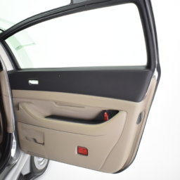
and additional steps that may be necessary for your specific model.
– It’s crucial to follow safety precautions when working on vehicles, especially when lifting and supporting heavy components.

This reverse-order approach should help you visualize the overall process of replacing the engine mount on a Mercedes Benz R Class W251.
The horn relay is a crucial component in a vehicle’s electrical system, primarily responsible for controlling the operation of the car’s horn. It acts as an intermediary between the horn switch, typically located on the steering wheel, and the horn itself. When the driver presses the horn button, a low-current signal is sent from the switch to the relay. The relay is designed to handle a much larger current needed to activate the horn, which would be too much for the horn switch to manage directly.

The horn relay consists of an electromagnetic coil and a set of contacts. When the switch is activated, the coil energizes, creating a magnetic field that pulls the contacts together, allowing a high-current flow from the battery to the horn. This process not only protects the horn switch from high current but also ensures that the horn can operate efficiently and loudly when needed.

In addition to its primary function, the horn relay can also act as a safeguard against electrical faults. If there is a short circuit or an overload, the relay can help prevent damage to the vehicle’s wiring by breaking the circuit. This component is typically located in the fuse box or near the horn itself, and while it can last for years, it may occasionally need replacement if the horn fails to operate properly. Overall, the horn relay is an essential part of a vehicle’s safety and communication system, allowing drivers to signal their presence to others on the road.

Download Jaguar Mark X 1961-1970 Workshop Repair Service Manual –

australia
Replacing the transmission output shaft on a Jaguar Mark X can be a complex task, but I’ll break it down into simpler steps for you. click here for more details on the download manual…..


    A close look at Jaguar XK engine ignition system The Jaguar XK engine is a remarkable unit, fabulously powerful, tough & reliable, in continuous production from 1948 until 1986.

    1965 Jaguar MK X

Before you begin, ensure you have the right tools and safety equipment. Here’s a step-by-step guide:

### tools and Supplies Needed:
– Socket set
– Wrenches
– Screwdrivers
– Pliers
– Jack and jack stands
transmission fluid
– Replacement output shaft
– Gasket or sealant (if needed)
– Safety glasses and gloves

### Step 1: Preparation
1. **Safety First**: Wear safety glasses and gloves to protect yourself.
2. **Gather Tools**: Make sure you have all the necessary tools and replacement parts ready before starting.
3. **Park the Car**: Find a flat, stable surface to work on and park your Jaguar Mark X. Turn off the engine and remove the keys.

### Step 2: Lifting the Vehicle
1. **Jack Up the Car**: Use a jack to lift the car from the front or rear, depending on where the transmission is located.
2. **Secure with Jack Stands**: Place jack stands under the vehicle to ensure it is stable and secure while you work.

### Step 3: Accessing the Transmission
1. **Remove the Underbody Cover**: If your vehicle has an underbody cover, remove it using a socket or wrench.
2. **Disconnect the Battery**: To prevent any electrical issues, disconnect the negative terminal of the battery.

### Step 4: Removing the transmission Components
1. **Drain the transmission Fluid**: Place a drain pan under the transmission and remove the drain plug to allow the fluid to drain out completely.
2. **Disconnect the Driveshaft**: Locate the driveshaft connected to the output shaft. Use a socket or wrench to remove the bolts securing it, and carefully slide it out.
3. **Remove transmission Mounts**: Identify and remove the transmission mount bolts to allow the transmission to drop slightly.
4. **Disconnect any Electrical Connectors**: If there are any electrical connectors attached to the transmission, carefully disconnect them.

### Step 5: Removing the Output Shaft
1. **Locate the Output Shaft**: Find the output shaft at the rear of the transmission.
2. **Remove the Output Shaft Retaining Bolt**: Use a socket or wrench to remove the bolt securing the output shaft.
3. **Slide Out the Output Shaft**: Gently pull the output shaft out from the transmission. You may need to wiggle it a bit to free it.

### Step 6: Installing the New Output Shaft
1. **Insert the New Output Shaft**: Take the new output shaft and slide it into the transmission where the old one was removed. Make sure it fits snugly.
2. **Secure with Retaining Bolt**: replace the retaining boltdownload Jaguar Mark X workshop manual and tighten it securely.

### Step 7: Reassembly
1. **Reconnect the Driveshaft**: Slide the driveshaft back into place and secure it with the bolts you removed earlier.
2. **Reattach transmission Mounts**: Line up the transmission and reattach the transmission mounts using the bolts.
3. **Reconnect Electrical Connectors**: Reattach any electrical connectors you may have disconnected earlier.

### Step 8: Final Steps
1. **Replace the Underbody Cover**: If you removed an underbody cover, reinstall it now.
2. **Refill transmission Fluid**: Use a funnel to refill the transmission with the appropriate type of fluid, following your vehicle’s specifications.
3. **Reconnect the Battery**: Reattach the negative terminal of the battery.

### Step 9: Lower the Vehicle
1. **Remove Jack Stands**: Carefully take out the jack stands and lower the vehicle using the jack.
2. **Test Drive**: Start the engine and take a short test drive to ensure everything is working properly. Check for any leaks or unusual noises.

### Conclusion
Replacing the transmission output shaft requires patience and attention to detail. If at any point you feel overwhelmed or unsure, it’s advisable to consult a professional mechanic. Always refer to your vehicle’s service manual for specific details and torque specifications. Good luck!
A bumper is a crucial component of a vehicle, designed primarily to absorb impact during low-speed collisions and protect both the vehicle’s structure and its occupants. Typically located at the front and rear ends of the car, bumpers play a vital role in vehicle safety and aesthetics. They are constructed from various materials, including plastic, fiberglass, and metals, often reinforced with energy-absorbing materials to enhance their protective capabilities.

In addition to their protective function, bumpers contribute to the overall design and style of the vehicle. Automakers often integrate bumpers with the vehicle’s body lines and features, making them an essential part of the car’s exterior. Modern bumpers may also house various technologies, such as sensors for parking assistance, cameras for rear visibility, and even radar systems for advanced driver-assistance systems (ADAS).

Bumpers are designed to withstand specific impact standards set by regulatory bodies, ensuring they can absorb energy and minimize damage. However, they also need to be lightweight to improve fuel efficiency and performance. In recent years, the automotive industry has seen a shift toward more sustainable materials for bumper manufacturing, aligning with broader environmental goals. Overall, the bumper is an integral part of vehicle safety, design, and functionality, reflecting the ongoing advancements in automotive engineering.

Download Kia Pregio 1995-2006 Repair Service Manual –

australia
Repairing the transmission cooler on a Kia Pregio involves a series of steps and requires specific tools. click here for more details on the download manual…..


    #autoservices #automobile #mechancial #mechanic #foryou#myanmar #youtube #car #kia #pregio #vict…

    Kia Pregio 3.0 | Piston Ring Gap Measuring Piston Ring Gap | Kia Pregio 3.0 JT Engine #kia #pregio.

Below is a detailed guide on how to approach this task, including the necessary tools and their descriptions:

– **Safety Gear**:
– **Gloves**: Protects your hands from harmful fluids and sharp edges.
– **Safety Glasses**: Shields your eyes from flying debris or splashes.

– **Basic Hand Tools**:
– **Socket Set**: Includes various sizes of sockets and a ratchet for removing bolts and nuts. Make sure to have metric sizes, as Kia vehicles typically use metric fasteners.
– **Wrench Set**: A set of open-end and box-end wrenches for accessing tight spaces where sockets can’t fit.
– **Screwdrivers**: Both flat-head and Phillips screwdrivers for removing clips or screws that may obstruct access to the cooler.

– **Pliers**:
– **Needle-Nose Pliers**: Useful for gripping small parts and removing hose clamps.
– **Channel Lock Pliers**: Ideal for clamping down on hoses or fittings.

– **Fluid Catch Pan**:
– **Oil Drain Pan**: To catch any transmission fluid that may spill during the repair, preventing mess and ensuring safe disposal.

– **Hose Clamps**:
– **Replacement Hose Clamps**: If the existing clamps are corroded or damaged, having new ones on hand will ensure a secure fit after repairs.

– **Transmission Fluid**:
– **Compatible Transmission Fluid**: Depending on the specifications of the Kia Pregio, ensure you have the right type and quantity of transmission fluid for refilling after the repair.

– **Transmission Cooler**:
– **Replacement Cooler**: If the cooler is damaged beyond repair, a new or remanufactured transmission cooler will be necessary.

– **Ratcheting Brace**:
– **Torque Wrench**: To ensure that bolts are tightened to the manufacturer’s specifications, which is crucial for preventing leaks.

– **Work Light**:
– **LED Work Light**: Provides adequate lighting in the workspace, especially If working under the vehicle.

– **Cleaning Supplies**:
– **Rags and Cleaners**: For cleaning any spills and wiping down components as needed. A degreaser can help remove old fluid residues.

### Step-by-Step Repair Process

– **Disconnect the Battery**:
– Disconnect the negative terminal to prevent any electrical issues while working.

– **Lift the Vehicle**:
– Use a jack and jack stands to raise the vehicle securely. Ensure safety by using wheel chocks on the opposite wheels.

– **Locate the Transmission Cooler**:
– The cooler is typically located in front of the radiator. Identify the cooler lines that connect the transmission to the cooler.

– **Drain Transmission Fluid**:
– Position the fluid catch pan under the transmission and remove the drain plug If available. Alternatively, loosen the cooler lines to let fluid drain into the pan.

– **Remove Cooler Lines**:
– Use pliers to loosen and slide the clamps off the cooler lines. Carefully pull the lines away from the cooler, allowing any remaining fluid to drain into the pan.

– **Remove the Cooler**:
– Unscrew any bolts or brackets securing the cooler in place using the socketdownload Kia Pregio workshop manual and wrench set. Carefully take out the cooler and inspect for damage.

– **Install New or Repaired Cooler**:
– Position the new or repaired cooler in place, securing it with bolts. Ensure it is aligned correctly with the mounting brackets.

– **Reattach Cooler Lines**:
– Reattach the cooler lines and secure them with new or existing hose clamps, ensuring a tight fit to prevent leaks.

– **Refill Transmission Fluid**:
– Remove the transmission dipstick and use a funnel to pour in the compatible transmission fluid until it reaches the proper level.

– **Reconnect the Battery**:
– Reconnect the negative terminal of the battery to restore power to the vehicle.

– **Start the Engine**:
– Start the engine and allow it to idle. Check for any leaks around the cooler lines and fittings.

– **Test Drive**:
– Take the vehicle for a short test drive to ensure proper operation and check for any unusual sounds or fluid loss.

– **Dispose of Old Fluid**:
– Properly dispose of any old transmission fluid according to local regulations.

### Additional Tips
always refer to the Kia Pregio service manual for specific torque specifications and fluid capacities.
If you are not confident in performing the repair, consider consulting a professional mechanic.
A brake booster, also known as a power brake booster, is a critical component in a vehicle’s braking system that enhances braking efficiency and reduces the effort required by the driver to apply the brakes. It is particularly important in modern vehicles, where the brake system is designed to provide maximum stopping power with minimal input from the driver.

The brake booster operates using vacuum pressure, typically derived from the engine. When the driver presses the brake pedal, a diaphragm within the booster is activated, causing a difference in pressure between the two sides of the diaphragm. this difference amplifies the force applied to the brake master cylinder. As a result, a small amount of pressure from the driver can translate into significantly greater pressure on the brake fluid, which is then transmitted to the brake calipers or drums to engage the brakes.

There are primarily two types of brake boosters: vacuum boosters and hydraulic boosters. Vacuum boosters are the most common and rely on engine vacuum to function, while hydraulic boosters utilize hydraulic pressure, often provided by the power steering system. A well-functioning brake booster is essential for safe vehicle operation, as a malfunction can lead to increased braking effort and decreased stopping power, which can compromise safety. regular maintenance and prompt attention to any signs of failure, such as a hard brake pedal or unusual noises, are crucial for ensuring optimal performance of this vital component.

Download HYUNDAI R55W-7 Wheel Excavator Service Repair Manual – ! –

bookshop
Performing a transmission fluid pressure test on a Hyundai R55W 7 Wheel Excavator involves several steps. click here for more details on the download manual…..


    Hyundai R330-9 final drive gear parts planetary carrier complete XKAQ-00536 XKAQ-00396 XKAQ-0019…

    engine overhaul|| engine head reface ||head gasket replacement ||engine overheat||#shorts #reels. honda #suzuki #toyota #reels #rebuild #repair #engine #overhaul #overheat #audi.

Here’s a simplified, reverse order guide to help you understand the process:

### 7. Analyze the Results
– **Check the Pressure Readings**: compare the pressure readings with the manufacturer’s specifications.
– **Identify Issues**: If the readings are outside the normal range, diagnose potential issues such as leaks, blockages, or pump failures.

### 6. Record and Document Findings
– **Take Notes**: Document the pressure readings and any observations made during the test for future reference.
– **Report Findings**: Communicate your results to the relevant personnel or maintenance team.

### 5. Remove the Pressure Gauge
– **Carefully Disconnect the Gauge**: Once testing is complete, carefully disconnect the pressure gauge from the test port.
– **Replace any Seals or Caps**: Ensure that any seals or caps are replaced to prevent leaks.

### 4. Monitor Pressure During Testing
– **Observe Pressure Readings**: While the engine is running and the transmission is in the correct mode (usually in gear), monitor the pressure readings on the gauge.
– **Take Note of Fluctuations**: Watch for any fluctuations in pressure which may indicate issues.

### 3. Prepare the Excavator
– **Warm Up the Transmission**: Start the engine and let the excavator warm up to operating temperature.
– **Ensure Safety**: engage the parking brake and ensure the excavator is on a level surface.

### 2. connect the Pressure Gauge
– **Locate the Test Port**: Identify the transmission pressure test port on the excavator.
– **Attach the Pressure Gauge**: connect the pressure gauge to the test port securely, ensuring there are no leaks.

### 1. Gather Tools and Equipment
– **Required Tools**: Obtain a pressure gauge suitable for transmission fluid pressure testing, along with any necessary adapters.
– **Safety Gear**: Wear appropriate personal protective equipment (PPE) such as Glovesdownload HYUNDAI R55W 7 Wheel Excavator workshop manual and safety glasses.

### Notes:
– Always refer to the specific service manual for the Hyundai R55W 7 Wheel Excavator for detailed specifications and procedures.
– Ensure that the test is performed in a safe environment, following all safety protocols.

This reverse order guide should help you understand the steps to perform a transmission fluid pressure test effectively.
The mass airflow sensor (MAF sensor) is a critical component of a vehicle’s engine management system, primarily responsible for measuring the amount of air entering the engine. This measurement is essential for the engine control unit (ECU) to optimize the air-fuel mixture for efficient combustion. Positioned between the air filter and the intake manifold, the MAF sensor works by detecting the mass of air flowing into the engine, allowing the ECU to adjust the fuel injectors accordingly.

There are two primary types of MAF sensors: hot wire and vane. The hot wire MAF sensor utilizes a thin wire heated by an electric current. As air flows over the wire, it cools down, causing the ECU to adjust the current to maintain a specific temperature. The amount of current required to keep the wire at that temperature correlates directly with the mass of air entering the engine. On the other hand, the vane type uses a mechanical flap that moves in response to airflow, providing a direct measurement of air volume.

A properly functioning MAF sensor is crucial for optimal engine performance, fuel efficiency, and reduced emissions. When the sensor malfunctions or becomes dirty, it can lead to symptoms like poor acceleration, rough idling, decreased fuel economy, and increased emissions. Regular maintenance and diagnostics can help ensure the MAF sensor operates effectively, contributing to the overall health and efficiency of the vehicle.

Download 2001 Honda Insight Repair Manual –

stores
– **Gather Necessary Tools and Materials** – **Brake Fluid**: Ensure you have the correct type of brake fluid for your Honda Insight. click here for more details on the download manual…..


    2019-2022 Honda Insight Dislikes /Hates Just a couple of things I’ve found to dislike or not really enjoy about this car. Give it a big thumbs up if you enjoyed the review!

    Indexing aftermarket spark plugs on a first generation 2000-2006 Honda Insight IMA Hybrid I bought a bunch of spark plugs from my local auto part store and indexing them by matching the threads on the new spark plugs …

– **Gather necessary Tools and Materials**
– **Brake Fluid**: Ensure you have the correct type of brake fluid for your Honda Insight. Typically, this will be DOT 3 or DOT 4 fluid. Check your owner’s manual for the specific recommendation.
– **Brake Bleeder Kit**: This can include a vacuum bleeder or a pressure bleeder. A basic kit often consists of a container to catch old fluid and a length of clear tubing.
– **Wrench or Socket Set**: necessary for loosening and tightening the bleeder screws on the brake calipers. A 10mm or 11mm wrench is usually appropriate.
– **Turkey Baster or Syringe**: Useful for removing old brake fluid from the master cylinder reservoir.
– **Rags/Paper Towels**: For cleaning up spills and wiping off tools.
– **Safety Glasses and Gloves**: To protect your eyes and skin from brake fluid, which can damage paint and irritate skin.

– **Prepare the Vehicle**
– **Park the Vehicle on a Level Surface**: Ensure the car is in a safe, flat area to prevent any rolling or movement during the process.
– **Engage the Parking Brake**: This will help secure the vehicle and prevent it from moving while you work.
– **Open the Hood**: Locate the brake fluid reservoir, which is typically found near the back of the engine bay, close to the driver’s side.

– **Remove Old Brake Fluid**
– **Check the Fluid Level**: Before draining, observe the current fluid level in the reservoir. If it’s low, this may indicate a leak or that it hasn’t been flushed in a while.
– **Siphon Out Old Fluid**: Using a turkey baster or syringe, carefully remove the old brake fluid from the reservoir. Dispose of it properly, as brake fluid is hazardous waste.
– **Clean the Reservoir**: Wipe the inside of the reservoir with a clean rag to remove any debris or sludge.

– **Add New Brake Fluid**
– **Fill the Reservoir**: pour fresh brake fluid into the reservoir, filling it to the indicated “full” line. Avoid overfilling, as the fluid will rise when the brakes are bled.

– **Bleed the Brakes**
– **Locate the Brake Bleeder Screws**: These are typically found on each brake caliper. start with the brake furthest from the master cylinder (usually the right rear), then move to the left rear, followed by the right front, and finally the left front.
– **Attach the Bleeder Hose**: Connect a clear plastic hose to the bleeder screw to direct fluid into a container. This will help prevent spills and allow you to see the fluid being expelled.
– **Open the Bleeder Screw**: Using the appropriate wrench, turn the bleeder screw counterclockwise to open it slightly.
– **Pump the Brake Pedal**: Have an assistant pump the brake pedal several times and then hold it down. This creates pressure in the brake system.
– **Close the Bleeder Screw**: While your assistant is holding the pedal down, quickly close the bleeder screw to avoid air entering the system. Then, instruct them to release the pedal.
– **Repeat as Necessary**: Continue this process until you see clear, new brake fluid coming out of the bleeder screw without bubbles. Make sure to check the fluid level in the master cylinder frequentlydownload Honda Insight workshop manual and refill as necessary to prevent it from running dry.

– **Finishing Up**
– **Tighten the Bleeder Screws**: Once all brakes have been bled, ensure that all bleeder screws are securely tightened to prevent leaks.
– **Check Brake Fluid Level Again**: After bleeding, check the fluid level in the reservoir one last time and top off if needed.
– **Test the Brake Pedal**: Before driving, gently press the brake pedal to ensure it feels firm and does not sink to the floor. This indicates that the system is properly bled.
– **Dispose of Old Brake Fluid**: Take the old brake fluid to a recycling center or an auto parts store that accepts hazardous waste.

– **Final Inspection**
– **Check for Leaks**: Look around the brake calipers and bleeder screws for any signs of leaking fluid.
– **Test Drive**: Take the car for a short test drive to ensure that the brakes are functioning correctly and feel responsive.

By following these steps, you can effectively perform a brake fluid flush on your Honda Insight, helping to maintain the braking system’s performance and safety.
The power steering pump is a vital component of a vehicle’s power steering system, which significantly enhances the driver’s ability to steer the vehicle with minimal effort. Its primary function is to generate hydraulic pressure that assists in turning the steering wheel, making it easier to navigate, especially at low speeds or during tight maneuvers.

Typically driven by a belt connected to the engine, the power steering pump draws fluid from the power steering reservoir and pressurizes it. This pressurized fluid is then directed to the steering gear, often a rack and pinion system, where it assists in moving the steering mechanism. The result is a smoother and more responsive steering experience, reducing the physical effort required from the driver.

Power steering pumps can be categorized into two main types: hydraulic and electric. Hydraulic pumps use fluid pressure, while electric pumps rely on electric motors to provide assistance. Over time, the power steering pump can experience wear and tear, leading to issues such as fluid leaks, noise during operation, or reduced steering assist. Regular maintenance, including checking fluid levels and inspecting for leaks, is essential for ensuring the longevity and performance of the power steering system. A malfunctioning pump can compromise vehicle handling and safety, making it crucial to address any issues promptly.

Download 1989 PEUGEOT 605 Service and Repair Manual –

workshop manual
Sure! click here for more details on the download manual…..


    PEUEGOT 605 шаровая и подшипник замена PEUGEOT 605 замена шаровой и реставрация ступечного подшипника.

    TOP Things that will BREAK on your Peugeot 605 How many miles is bad for a used Peugeot 605? Are used Peugeot 605 1990 – 1999 expensive to maintain?

Suspension alignment, often referred to as wheel alignment, is an important process that ensures your car’s wheels are positioned correctly. Proper alignment helps improve handling, tire wear, and overall safety. Here’s a simple explanation of how to do a suspension alignment on a Peugeot 605, tailored for those with little mechanical experience.

### What You’ll Need:
1. **A flat surface**: A smooth, level area to work on your car.
2. **Tools**: Basic hand tools like a wrench, socket set, and possibly a ruler or alignment tool (you can borrow or rent specialized tools).
3. **A friend**: It’s always helpful to have an extra set of hands.

### Steps for Suspension Alignment:

1. **Check Tire Pressure**:
– Before you start, make sure all tires are inflated to the manufacturer’s recommended pressure. This information is usually found on a sticker inside the driver’s door or in the owner’s manual.

2. **Inspect the Suspension**:
– Look for any visible signs of wear or damage in the suspension components (like the shocks, struts, and control arms). If something looks broken or worn out, it might need to be replaced before alignment.

3. **Position the Car**:
– Park the Peugeot 605 on a flat surface. Ensure the steering wheel is centered and the vehicle is in neutral (or park if it’s an automatic) with the brakes engaged.

4. **Measure Wheel Alignment**:
– **Toe**: This is the angle at which the tires point in relation to each other. You can measure it by placing a ruler or a measuring tape from the front of the tires to the back of the tires. Ideally, the front measurement should be slightly less than the back measurement.
– **Camber**: This is the tilt of the wheels. You can use a level to check if the top of the tires leans in or out. Ideally, they should be vertical.
– **Caster**: This is a bit trickier, as it involves the angle of the steering axis. It usually requires specialized tools or a professional setup.

5. **Adjustments**:
– If you notice any misalignment, you can adjust it using the adjustment bolts located on the suspension components. This may involve loosening the bolts, adjusting the suspension component to the desired position, and then tightening the bolts back.

6. **Test Drive**:
– After making adjustments, take the car for a short test drive. Pay attention to how it handles. If the car pulls to one side or if the steering feels off, you may need to make further adjustments.

7. **Final Check**:
– After the test drive, recheck your measurements to ensure everything is where it should be.

### Important Notes:
– **Professional Help**: If you’re unsure or uncomfortable doing this yourself, it’s best to take your Peugeot 605 to a professional mechanic or alignment specialist. They have the toolsdownload PEUGEOT 605 workshop manual and expertise to get it right.
– **Regular Maintenance**: Regularly checking your alignment is important, especially if you hit a pothole or curb, or if you notice uneven tire wear.

By following these steps, you can better understand how to perform a suspension alignment on your Peugeot 605, even with little mechanical experience!
A turbocharger is a crucial component in modern internal combustion engines, designed to enhance engine performance by increasing the amount of air entering the combustion chamber. This device operates on the principle of forced induction, which compresses the intake air, allowing for a higher density of oxygen to mix with fuel. Consequently, this results in a more powerful combustion process, leading to increased power output and efficiency.

The turbocharger consists of two main parts: the turbine and the compressor. The turbine is connected to the engine’s exhaust system, where it harnesses the energy from the exhaust gases produced during combustion. As these gases flow through the turbine, they spin it at high speeds. This rotational energy is then transferred to the compressor, which draws in ambient air and compresses it before sending it into the engine’s intake manifold. By forcing more air into the cylinders, a turbocharger enables the engine to burn more fuel, thereby increasing power without significantly increasing engine size or weight.

Turbochargers are particularly advantageous in performance applications, as they provide a significant boost in horsepower and torque, enhancing acceleration and overall driving experience. Additionally, they can improve fuel efficiency by allowing smaller engines to produce equivalent power levels of larger, naturally aspirated engines. This makes turbochargers popular in both performance vehicles and everyday cars, contributing to reduced emissions and better fuel economy. However, they do require careful management of heat and pressure to ensure longevity and optimal performance.

Download Volvo EC35C Compact Excavator Workshop Service Manual –

sale
Repairing the power steering system on a Volvo EC35C Compact Excavator involves several steps. click here for more details on the download manual…..


    Volvo EC35C Mini Excavator For Sale inspection video! View our current inventory*** @ http://www.quesalesinc.com/… We can help you arrange freight. We deal with several different …

    How To Detach and Attach Volvo Excavator Universal Quick Coupler Step by step instructions for detaching and attaching the universal quick coupler for Volvo E-Series excavators.

Below is a detailed guide on how to perform this repair, including descriptions of the components involved.

### Components of the Power Steering System

1. **Power Steering Pump**: This component provides hydraulic pressure to the steering system. It is typically belt-driven from the engine.

2. **Power Steering Fluid Reservoir**: This tank holds the hydraulic fluid used in the steering system. It usually has a dipstick or a sight glass for checking fluid levels.

3. **Hydraulic Lines**: These hoses and tubes carry hydraulic fluid between the power steering pump, the steering gear, and the reservoir.

4. **Steering Gear (or Rack and Pinion)**: This component translates the rotational motion of the steering wheel into linear motion to turn the wheels.

5. **Steering Wheel**: The driver’s input device that provides manual control over the steering system.

6. **Steering Column**: Connects the steering wheel to the steering gear and may include universal joints for flexibility.

7. **Power Steering Fluid**: The hydraulic fluid that transmits power within the system. It’s crucial to use the correct type of fluid specified by the manufacturer.

### Tools and Materials Needed

– Hydraulic fluid (specific to Volvo EC35C)
– Wrenches and sockets
– Screwdrivers
– Pliers
– Hose clamps
– Towels/rags for cleanup
– A container for draining old fluid
– New hydraulic hoses (if needed)
– Replacement power steering pump (if necessary)
torque wrench
– Safety gloves and goggles

### Step-by-Step Repair Process

#### 1. Safety Precautions
– Ensure the excavator is on a flat surface and turned off.
– Engage the parking brake.
– Wear safety gloves and goggles to protect yourself from hydraulic fluid.

#### 2. inspect the Power Steering System
– **Check Fluid Level**: open the power steering fluid reservoir and check the fluid level. If it’s low, top it off with the correct fluid.
– **Look for Leaks**: inspect hydraulic lines, the power steering pump, and the steering gear for any signs of leaks.

#### 3. Drain the Power Steering Fluid
– Place a container under the power steering fluid reservoir.
– Disconnect the return line from the reservoir and allow the fluid to drain completely.

#### 4. Remove the Power Steering Pump
– **Locate the Pump**: The power steering pump is typically mounted on the engine.
– **Disconnect Hoses**: Use wrenches to disconnect the high-pressure and return hoses from the pump.
– **Remove the Pump**: Unbolt the pump from its mounting using the appropriate socket and remove it from the engine.

#### 5. inspect and Replace the Power Steering Pump (if necessary)
– If the pump is damaged or not functioning properly, replace it with a new unit.
– Ensure the new pump is compatible with the Volvo EC35C specifications.

#### 6. Replace Hydraulic Hoses (if necessary)
– If any hoses are worn or leaking, replace them.
– Use the correct typedownload Volvo EC35C Compact Excavator workshop manual and size of hoses to ensure proper fit and function.

#### 7. Reinstall the Power Steering Pump
– Position the new or repaired pump back in its mounting location.
– Bolt it in place and reconnect the high-pressure and return hoses, ensuring they are tightly secured.

#### 8. Refill Power Steering Fluid
– Reconnect the return line to the reservoir.
– Fill the reservoir with the correct type of power steering fluid up to the indicated level.

#### 9. Bleed the Power Steering System
– Start the engine and let it idle.
– Turn the steering wheel from lock to lock several times to help purge any air from the system.
– Check the fluid level again and top off if necessary.

#### 10. Test the System
– With the engine still running, check for any leaks around the pump, hoses, and reservoir.
– Test drive the excavator to ensure the steering is responsive and there are no unusual noises.

#### 11. Clean Up
– Dispose of the old hydraulic fluid and any debris in accordance with local regulations.
– Clean any spills and ensure all tools are accounted for.

### Conclusion
Repairing the power steering on a Volvo EC35C Compact Excavator requires attention to detail and a methodical approach. By following the steps above and ensuring that you use the correct parts and fluids, you can successfully repair the power steering system and maintain the performance of your excavator. If you encounter persistent issues, it may be best to consult with a professional mechanic or technician.
The power steering pump pulley is a crucial component in a vehicle’s power steering system, designed to facilitate the smooth and effortless steering of the vehicle. Typically made from materials like aluminum or plastic, the pulley is a circular device that connects to the power steering pump via a belt. The primary function of the power steering pump is to generate hydraulic pressure that assists the driver in turning the steering wheel, especially at low speeds or during parking maneuvers.

When the engine runs, the crankshaft rotates the drive belt, which in turn spins the power steering pump pulley. This rotation powers the pump, which pushes hydraulic fluid through the system. The hydraulic fluid aids in moving the steering gear, reducing the effort required by the driver to turn the wheel.

The efficiency of the power steering system heavily relies on the condition of the power steering pump pulley. If the pulley becomes worn or damaged, it can lead to belt slippage, reduced hydraulic pressure, and ultimately, less effective steering assistance. In some cases, a faulty pulley can generate noise or vibrations that indicate a problem. Regular maintenance checks are essential to ensure that the pulley and the entire power steering system function optimally, providing safe and responsive steering performance for the vehicle.

Download BMW 328i 2004Service Repair Manual –

workshop manual
Performing a ball joint replacement on a BMW 328i is a complex task that requires mechanical knowledge, tools, and safety precautions. click here for more details on the download manual…..


    Turbocharge Your BMW – BMW N52/N51 Turbo Kit – BMW 328i Turbo Kit – Verstarken Auto Turbocharge Your BMW – BMW N52/N51 Turbo Kit – https://www.verstarkenauto.com/ BMW 328i Turbo Kit – BMW Tuning – BMW …

    How To Replace Shocks and Struts in a BMW E90 Convertible 328I-335I 2007-2012 Suspension problem in your BMW E90 Convertible 328I-335I? AutoZone shows you how to replace shocks and struts easily with …

Below is a reverse order of steps to replace the ball joint. Please note that this is a high-level overview; consulting a repair manual or a professional is recommended for detailed instructions and safety guidelines.

### Reverse Order Steps for Ball Joint Replacement

1. **Reattach Wheel and Lower Vehicle**
– Reinstall the wheel and lug nuts, tightening them securely.
– Lower the vehicle to the ground using a jack.

2. **Reassemble Suspension Components**
– Reattach any suspension components that were disconnected.
– Make sure all bolts are tightened to the manufacturer specifications.

3. **Install New Ball Joint**
– Position the new ball joint into the control arm or knuckle.
– Use a ball joint press tool to properly seat the ball joint if necessary.
– Secure the ball joint with the retaining nut and tighten it to the specified torque.

4. **Remove Old Ball Joint**
– If the ball joint is pressed into the control arm, use a ball joint separator tool to remove it.
– Disconnect the ball joint from the control arm or steering knuckle.

5. **Prepare the Vehicle**
– Safely lift the vehicle using a jack and secure it with jack stands.
– Remove the front wheel on the side where you are replacing the ball joint.

6. **Disconnect Suspension Components**
– Remove any components that obstruct access to the ball joint, such as the tie rod end or stabilizer link.
– Ensure to note the order and orientation for reassembly.

7. **Remove the Control Arm (if necessary)**
– Depending on the design, you may need to remove the control arm to gain access to the ball joint.
– Unbolt the control arm from the chassis and any other connections.

8. **Gather Tools and Parts**
– Ensure you have the necessary tools: a jack, jack stands, wrenches, sockets, a ball joint press, and safety equipment.
– Obtain the correct replacement ball joint for your BMW 328i.

### Important Notes
– Always consult a repair manual specific to your BMW model for torque specifications and detailed procedures.
– Safety is a priority; ensure the vehicle is securely lifteddownload BMW 328i workshop manual and supported before beginning work.
– It is advisable to perform this task in a clean, well-lit environment.
– If you’re unsure or inexperienced, consider seeking assistance from a professional mechanic.

This guide is intended for informational purposes only. Always prioritize safety and proper techniques when working on vehicles.
Clear coat is a transparent layer of paint that is applied over the base color of a vehicle’s exterior. Its primary function is to protect the underlying paint from environmental damage, including UV rays, dirt, chemicals, and other corrosive elements. The clear coat enhances the longevity and durability of the paint, preventing it from fading, chipping, or peeling over time. This layer is crucial for maintaining the aesthetic appeal of the vehicle, as it provides a glossy finish that enhances the depth and richness of the color beneath it.

Typically made from a polyurethane or acrylic resin, clear coats can vary in thickness and composition, influencing their protective qualities and appearance. High-quality clear coats often include additives that enhance their resistance to scratches and abrasions, as well as those that provide better resistance to solvents and chemicals commonly found in the environment.

In addition to protection, clear coats can also improve the overall appearance of a vehicle. They create a smooth, shiny surface that reflects light, giving the car a polished and well-maintained look. However, clear coats can also suffer from wear and tear over time, leading to issues such as oxidation, yellowing, or cracking. Therefore, regular maintenance, including washing and waxing, is essential to preserve the integrity of the clear coat and, by extension, the vehicle’s paintwork. Overall, clear coat plays a vital role in vehicle aesthetics and longevity, making it an essential component of automotive finishes.

Download 2009 FORD F150 F-150 Workshop Service Repair Manual –

fix
Replacing the control arm on a Ford F-150 involves several steps, and it is essential to have the right tools and components to complete the job safely and efficiently. click here for more details on the download manual…..


    This F150 rebuild is so bad you wouldn't buy it blindfolded! These sellers were not trying to hide anything with their shoddy work on this third-party auction car. They just got in way over their …

    Ford F-150 Buyers Guide | What would a Ford Tech Buy? Ford F-150 Buyers guide In this video I break down the best and worst of the F-150. Complete guide to choosing the right F-150 …

The control arm is a crucial component of the vehicle’s suspension system, connecting the chassis to the wheel assembly and allowing for vertical movement while maintaining proper wheel alignment.

### Tools and Materials Needed

1. **Tools:**
– Socket set (metric and standard)
– Wrench set
– Torque wrench
– Ball joint separator or pickle fork
– Pry bar
– Hammer
– Jack and jack stands
– Wheel chocks
rubber mallet
– Screwdrivers (flathead and Phillips)
– Pliers
– Safety glasses
– Gloves

2. **Replacement Parts:**
– New control arm (left or right, depending on which one you are replacing)
– New control arm bushings (if not already included with the control arm)
– New ball joint (if not already included with the control arm)
– New hardware (bolts, nuts, washers, If needed)

### Step-by-Step Control Arm Replacement

#### Preparation

1. **Safety First:**
– Park the vehicle on a flat surface.
– Engage the parking brake and place wheel chocks behind the rear wheels.

2. **Lift the Vehicle:**
– Use a jack to lift the front of the vehicle.
– Place jack stands under the vehicle’s frame to support it securely.

#### Removal of the Old Control Arm

3. **Remove the Wheel:**
– Use a lug wrench to remove the lug nuts from the wheel on the side you are working on.
– Take off the wheel and set it aside.

4. **Access the Control Arm:**
– Locate the control arm. It is usually connected to the frame on one end and the steering knuckle on the other.

5. **Disconnect the Ball Joint:**
– Locate the ball joint at the steering knuckle.
– Use a ball joint separator or pickle fork to disconnect the ball joint from the steering knuckle.
– You may need to remove a cotter pin and nut before separating the joint.

6. **Remove the Control Arm Bolts:**
– Locate the bolts that attach the control arm to the frame.
– Use the appropriate socket to remove these bolts. Keep track of the bolts and nuts for reinstallation If they are not provided with the new control arm.

7. **Remove the Control Arm:**
– Gently pry the control arm away from its mounting point, and then remove it from the vehicle. Be careful not to damage any surrounding components.

#### installation of the New Control Arm

8. **Prepare the New Control Arm:**
If the new control arm does not come with a ball joint or bushings, install them according to the manufacturer’s instructions.

9. **Install the New Control Arm:**
– Position the new control arm into place where the old one was removed.
– Insert the bolts through the bushingsdownload FORD F150 F 150 workshop manual and into the frame. Hand-tighten the bolts to hold the control arm in place.

10. **Reconnect the Ball Joint:**
– Align the ball joint with the steering knuckle and press it into place.
– Reattach the nut and tighten it to the manufacturer’s specifications (usually found in a repair manual or online).

11. **Torque Bolts:**
– Use a torque wrench to tighten all control arm bolts to the manufacturer’s specifications. This is crucial for safety and performance.

#### Final Steps

12. **Reinstall the Wheel:**
– Place the wheel back onto the hub and hand-tighten the lug nuts.

13. **Lower the Vehicle:**
– Carefully remove the jack stands and lower the vehicle back to the ground.

14. **Tighten the Lug Nuts:**
– Once the vehicle is on the ground, use a torque wrench to tighten the lug nuts to the correct specifications in a crisscross pattern to ensure even tension.

15. **Test Drive:**
– Before driving normally, take a short test drive to ensure that everything feels stable. Listen for any unusual noises that could indicate improper installation.

### Conclusion

Replacing the control arm on a Ford F-150 can be a rewarding task If done properly. It is critical to follow safety precautions and torque specifications to ensure the vehicle remains safe to drive. If you are unsure about any step in the process, consult a professional mechanic or refer to a service manual specific to your Ford F-150 model.
Brake pads are a crucial component of a vehicle’s braking system, designed to create friction against the brake rotors, which in turn slows down or stops the vehicle. Typically made from a mixture of materials such as organic compounds, semi-metallic substances, or ceramics, brake pads are positioned within the brake caliper, which houses the brake rotor. When the driver presses the brake pedal, hydraulic pressure forces the caliper to compress the brake pads against the rotor. This friction generates the necessary stopping power.

The effectiveness of brake pads is vital for vehicle safety, as they directly influence stopping distance and overall braking performance. Over time, brake pads wear down due to the constant friction and heat generated during braking, which necessitates regular inspections and replacements. Most manufacturers recommend replacing brake pads every 30,000 to 70,000 miles, although this can vary based on driving habits, vehicle type, and environmental conditions.

Additionally, brake pads can produce noise when they are worn down, often manifesting as a squealing or grinding sound, which serves as an audible warning to the driver. The choice of brake pads can also affect the driving experience; for instance, higher-performance pads may offer better stopping power but could produce more dust and noise. Ultimately, maintaining and replacing brake pads in a timely manner is essential for ensuring safe vehicle operation and optimal braking efficiency.

Download 2013 Mercedes-Benz CLA250 (C117) 4MATIC OEM Download Service & Repair Manual Software –

australia
Replacing the upper control arm on a Mercedes-Benz CLA250 C117 4MATIC requires a good understanding of the vehicle’s suspension components and a careful approach to ensure safety and proper functionality. click here for more details on the download manual…..


    HIDDEN COMPARTMENTS AND CUPHOLDERS – Mercedes-Benz CLA Hidden compartments and cupholders locations are located through various places with in your vehicle. This particular video …

    🚗 🚕 2014 Mercedes-Benz CLA250 Tire Size 🔴 2014 Mercedes-Benz CLA250 Tire Size ______ Subscribe for More Rideshare Info Here: …

Here’s a detailed step-by-step guide to help you through the process, including descriptions of every component involved.

### Tools and Materials Needed:

1. **Tools:**
– Socket set (including 10mm, 13mm, 15mm, 17mm, and larger sockets)
– Wrench set (ratcheting preferred)
– Torque wrench
– Ball joint separator tool or pickle fork
– Rubber mallet
– Jack stands
– Floor jack
– Screwdrivers (flathead and Phillips)
– Pry bar
– Pliers
– Safety goggles and gloves

2. **Materials:**
– New upper control arm (OEM recommended)
– New rubber bushings (if not included with the control arm)
– New cotter pins (if applicable)
– Grease (if required for bushings)
– Loctite (thread locking compound, optional)

### Steps for Upper Control Arm Replacement:

#### 1. **Preparation:**
– Park the vehicle on a flat surface, engage the parking brake, and wear safety goggles and gloves.
– Gather all tools and parts needed for the replacement.

#### 2. **Lifting the Vehicle:**
– Use a floor jack to lift the front of the vehicle.
secure the vehicle with jack stands to ensure it is stable and safe to work under.

#### 3. **Remove the Wheel:**
– Using a lug wrench, loosen and remove the lug nuts on the front wheel where the control arm is being replaced.
– Remove the wheel and set it aside.

#### 4. **Accessing the Upper Control Arm:**
– Locate the upper control arm, which is mounted to the chassis and also connects to the steering knuckle.
– You will see the upper control arm has two mounting points: one at the chassis (typically a bolt) and another at the steering knuckle (a ball joint).

#### 5. **Removing the Upper Control Arm:**
– **Disconnect from Steering Knuckle:**
– Remove the cotter pin (if applicable) and the nut securing the ball joint to the steering knuckle using the appropriate socket.
– Use a ball joint separator tool or a pickle fork to separate the ball joint from the steering knuckle. Be cautious to avoid damaging the knuckle.

– **Remove Control Arm Bolts:**
– Locate and remove the bolts securing the upper control arm to the chassis. These may require a 10mm, 13mm, or larger socket.
– Support the control arm with one hand while removing the bolts to prevent it from falling.

#### 6. **Installing the New Upper Control Arm:**
– Position the new upper control arm in place, aligning it with the bolt holes on the chassis and the steering knuckle.
– Insert the bolts securing the upper control arm to the chassis and hand-tighten them initially.

– **Reconnect Ball Joint:**
– Align the ball joint with the steering knuckle and insert it.
secure it with the nut and tighten it to the manufacturer’s specifications using a torque wrench. Insert a new cotter pin if applicable.

#### 7. **Finalizing Installation:**
– Once all bolts are tightened, check that everything is secure.
– If the control arm has bushings, ensure they are properly seated and lubricated as necessary.

#### 8. **Reinstalling the Wheel:**
– Place the wheel back onto the hubdownload Mercedes Benz CLA250 C117 4MATIC OEM workshop manual and hand-tighten the lug nuts.
– Lower the vehicle from the jack stands and onto the ground.

#### 9. **Torque Wheel Lug Nuts:**
– Use a torque wrench to tighten the lug nuts to the manufacturer’s specified torque settings, ensuring they are properly secured.

#### 10. **Check Alignment:**
– After replacing suspension components like the upper control arm, it’s important to have the vehicle’s wheel alignment checked and adjusted if necessary. This ensures proper handling and tire wear.

### final Notes:
– Always refer to the specific service manual for your Mercedes-Benz CLA250 C117 4MATIC for exact torque specifications and any unique procedures that may be required.
– If you are unsure or uncomfortable with any step in this process, it may be best to consult a professional mechanic.
The High beam switch is a crucial component in a vehicle’s lighting system, responsible for controlling the operation of the High beam headlights. Positioned typically on the steering column or as a part of the headlight control system, this switch allows the driver to toggle between low and High beam settings. The primary function of High beams is to provide increased illumination for the road ahead, particularly in rural or poorly lit areas, enhancing visibility during nighttime driving.

When activated, High beams produce a more intense and focused beam of light, which can illuminate a greater distance compared to low beams. However, the use of High beams is regulated by traffic laws, as they can cause glare for oncoming drivers. The High beam switch usually allows for a momentary activation, enabling drivers to flash their High beams to signal to other road users, such as alerting oncoming traffic or indicating to a driver that they can proceed.

Modern vehicles may feature automatic High beam systems that utilize sensors to detect oncoming headlights or tail lights, automatically switching between High and low beams for optimal safety and convenience. Overall, the High beam switch plays a vital role in enhancing nighttime driving safety, allowing drivers to adapt their visibility to different driving conditions.