Download CATERPILLAR CAT 3208 Diesel Truck Engine Workshop Manual –

online
Repairing an alternator on a Caterpillar CAT 3208 truck engine can seem daunting, but with a clear step-by-step approach, you can tackle it. click here for more details on the download manual…..


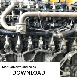
    The Cat 3208 Engine. Know Your Engine. Engine Design And Problems. Cat 3208. The Cat 3208 had along production run and can still be found in several different industries. This video goes over the engine …

    She replaces the Main Engine Starter on a caterpillar 3208 Watch as this beautiful blond tackles a heavy-duty diesel engine starter, specifically the Caterpillar 3208ta. This video showcases …

Here’s a simple guide to help you understand the process, even if you have little mechanical experience.

### What is an Alternator?
The alternator is an important part of your truck’s electrical system. It generates electricity to charge the battery and power electrical systems while the engine is running.

### Tools You’ll Need:
1. **Basic Hand Tools:** Wrenches, socket set, screwdrivers
2. **Safety Gear:** Gloves and safety glasses
3. **Multimeter:** For testing electrical connections
4. **Replacement Parts:** If needed (new alternator or repair kit)

### Step-by-Step Repair Process:

#### 1. **Safety First:**
– Make sure the truck is parked on a flat surface and the engine is turned off.
– Disconnect the battery by removing the negative (-) terminal first. This prevents any electrical shock or short circuits.

#### 2. **Locate the Alternator:**
– Open the hood of the truck.
– The alternator is usually mounted on the front side of the engine. It looks like a round metal piece with a belt attached to it.

#### 3. **Inspect the Alternator:**
– Check for any visible signs of damage, such as cracks or loose wires.
– Look for any broken or worn belts. If the belt is damaged, it may need to be replaced.

#### 4. **Remove the Belt:**
– If the belt is in good condition and you’re just checking the alternator, you can skip this step. Otherwise, use a wrench to loosen the tensioner pulley (the part that holds the belt tight) and slide the belt off the alternator.

#### 5. **Disconnect Electrical Connections:**
– Carefully unplug any electrical connectors attached to the alternator. Take a picture or make a note of where each wire goes for reassembly.

#### 6. **Remove the Alternator:**
– Use a socket wrench to unscrew the bolts that hold the alternator in place. There are usually two or three bolts. Keep these in a safe place to reuse later.

#### 7. **Install the New or Repaired Alternator:**
– If you’re replacing the alternator, take the new unit and place it where the old one was. Secure it with the bolts you removed earlier.
– If you’re repairing the alternator, follow the repair kit instructions to fix any internal components.

#### 8. **Reconnect the Electrical Connections:**
– Reattach the electrical connectors to the new or repaired alternator, referring to your earlier notes or pictures.

#### 9. **Reinstall the Belt:**
– Place the belt back onto the alternator. Use the tensioner pulley to tighten it back into place. Make sure the belt is properly seated.

#### 10. **Reconnect the Battery:**
– Reconnect the negative (-) terminal of the battery first. This is important to prevent any sparks.

#### 11. **Test the Alternator:**
– Start the enginedownload CATERPILLAR CAT 3208 Truck Engine workshop manual 
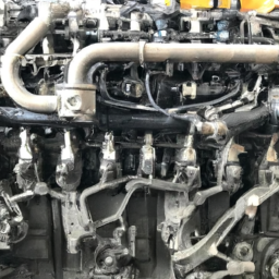
and check that the alternator is working. Use a multimeter to check the voltage; it should be around 13.8 to 14.4 volts when the engine is running. If the voltage is outside this range, you may need to troubleshoot further.

### Final Tips:
– Always consult the owner’s manual for specific details related to your truck.
– If you feel unsure at any step, don’t hesitate to ask for help from someone with more mechanical experience.
– Keep your workspace organized and clean to avoid losing small parts.

With patience and careful attention to detail, you can successfully repair the alternator on your Caterpillar CAT 3208 truck engine!
A jack stand is a critical safety device used in automotive maintenance and repairs to support a vehicle after it has been lifted with a hydraulic or mechanical jack. Typically constructed from sturdy materials like steel or aluminum, jack stands are designed to provide a secure and stable platform for the vehicle, ensuring that it remains elevated and does not collapse during servicing.

When a car is lifted using a jack, it is crucial to place jack stands underneath the vehicle to prevent potential accidents. Jacks can fail, especially if they are overloaded or malfunction, and jack stands serve as a fail-safe measure. They come in various sizes and weight capacities, allowing users to select the appropriate stand for their specific vehicle type and weight.

Most jack stands have a ratchet mechanism or a pin-locking design that allows for height adjustment. This feature enables users to set the stands at the desired height to accommodate different vehicle models and provide adequate clearance for access to the undercarriage.

Using jack stands is essential for tasks such as changing tires, performing brake work, or inspecting the undercarriage. Safety is paramount when working under a vehicle; therefore, employing jack stands is a best practice that ensures both the safety of the technician and the integrity of the vehicle during repairs. Overall, jack stands are indispensable tools in any mechanic’s arsenal, contributing significantly to safe automotive servicing.

Download Kobelco K905LC-II Parts-

do your own repairs
Replacing the input shaft bearing on a Kobelco K905LC II excavator involves several steps, and it’s important to follow the manufacturer’s guidelines for safety and accuracy. click here for more details on the download manual…..


    Engine Mounting Rubber 2416Z574 2416Z573 2416Z498 for Kobelco K904-2 SK100-3 SK120-3 SK120LC-3 8 PCS Engine Mounting Rubber Cushion 2416Z574 2416Z573 2416Z498 for Kobelco Excavator K904-2 K904L-2 K905-2 …

Below is a detailed description of the components and the process involved in replacing the input shaft bearing.

### Components Involved:

1. **Input shaft Bearing**: This is the bearing that supports the input shaft and allows it to rotate smoothly. It is crucial for the proper functioning of the drivetrain.

2. **Input Shaft**: The shaft that transmits power from the engine to the drivetrain. It connects to the transmission.

3. **Bearing Housing**: This is the component that holds the input shaft bearing in place. It is often bolted to the transmission case.

4. **Gasket/Seals**: Gaskets and seals prevent leaks and keep contaminants out of the bearing housing.

5. **Fasteners**: Bolts and nuts that secure the bearing housing and other components.

6. **Tools**: Common tools required for this job include wrenches, sockets, a bearing puller, a hammer, a torque wrench, and possibly special tools designed for bearing installation.

### Tools Required:

– Socket set
– Wrench set
– Torque wrench
– Bearing puller
– Hammer
– Screwdrivers
– Pliers
– Clean cloths
– Lubricant (grease or oil)
– Safety equipment (gloves, goggles)

### Step-by-Step Replacement Procedure:

1. **Safety Precautions**:
– Park the excavator on a flat surface and engage the parking brake.
– Disconnect the battery to prevent any electrical hazards.
– Use safety glasses and gloves for protection.

2. **Remove the Cover**:
– Locate the cover over the input shaft bearing. This may involve removing access panels or covers.
– Use the appropriate tools to remove any bolts or fasteners securing the cover.
– Carefully lift off the cover and set it aside.

3. **Drain Transmission Fluid**:
– If necessary, drain the transmission fluid to prevent spills during the bearing replacement.
– Locate the drain plug on the transmission case and remove it to allow the fluid to drain completely.

4. **Remove the Input Shaft**:
– Depending on the design, you may need to remove other components or parts that obstruct access to the input shaft.
– Use a bearing puller to remove the input shaft from its position if it is stuck.
– Gently tap it out with a hammer if necessary, ensuring that you do not damage any surrounding components.

5. **Remove the Old Bearing**:
– Once the input shaft is out, access the bearing housing where the input shaft bearing is located.
– Use the bearing puller to remove the old input shaft bearing. Be careful not to damage the bearing housing.
– Inspect the bearing housing for any signs of wear or damage.

6. **Clean the Area**:
– Clean the bearing housingdownload Kobelco K905LC II Parts workshop manual and the surrounding area to remove any debris or old gasket material.
– Use a clean cloth and appropriate cleaning solution if necessary.

7. **Install the New Bearing**:
– Apply a thin layer of lubricant to the new input shaft bearing.
– Carefully place the new bearing into the bearing housing.
– Use a bearing installation tool or a soft-faced hammer to tap the bearing into place gently. Ensure it is seated evenly.

8. **Reinstall the Input Shaft**:
– Align the input shaft with the new bearing and insert it back into position.
– Ensure it is seated correctly and rotates smoothly.

9. **Reattach the Cover**:
– If there is a gasket or seal, replace it with a new one to prevent leaks.
– Reattach the cover over the input shaft bearing and secure it with the appropriate fasteners.
– Torque the bolts to the manufacturer’s specifications.

10. **Refill Transmission Fluid**:
– If you drained the transmission fluid earlier, refill it to the appropriate level.
– Check for any leaks around the newly installed bearing.

11. **Reconnect the Battery**:
– Reconnect the battery and ensure all electrical connections are secure.

12. **Test the Excavator**:
– Start the excavator and perform a test run to ensure everything is functioning correctly. Listen for any unusual noises and check for leaks.

### Conclusion:
Replacing the input shaft bearing on a Kobelco K905LC II excavator requires careful attention to detail and adherence to safety protocols. Following these detailed steps will help ensure a successful replacement. Always consult the operator’s manual or service manual for specific torque values and additional procedures related to your excavator model.
The grille emblem is a distinctive and often iconic component found on the front of many vehicles, typically positioned prominently within the vehicle’s grille. This emblem serves multiple purposes, both functional and aesthetic. Primarily, it acts as a branding element, showcasing the manufacturer’s logo or name, which contributes to the vehicle’s identity and recognition. Whether it features a stylized letter, a symbol, or a combination of both, the grille emblem is a critical aspect of a car’s overall design language.

Beyond branding, the grille emblem can play a role in the vehicle’s aerodynamics. In some cases, it is designed to enhance airflow to the engine or cooling systems, which can be crucial for performance. The placement of the emblem often aligns with the vehicle’s design philosophy, complementing the lines and contours of the front fascia.

Additionally, grille emblems can vary in materials and finishes, ranging from chrome and metallic finishes to more modern, minimalist designs using plastic or composite materials. Some emblems are illuminated, adding a contemporary touch and improving visibility in low-light conditions. The grille emblem not only contributes to the visual appeal of the vehicle but also helps establish a connection between the driver and the brand, making it a significant element in automotive design and marketing.

Download 2005 BMW Z4 (E85) OEM Download Service & Repair Manual Software –

repair
Flushing the brake fluid in a BMW Z4 E85 is an important maintenance task that helps ensure your braking system works effectively. click here for more details on the download manual…..


    3 SERIOUS COMMON ISSUES – BMW Z4 (e85) | 2003 – 2008 production years

    Remove Automatic Shift Knob | BMW Z4 2003-2008 A/T Knobs LCI Black: https://geni.us/UkXo LCI Beige: https://geni.us/ujk1hga LCI Black Chrome: https://geni.us/E3SbXA LCI Beige …

Brake fluid can absorb moisture over time, which can reduce its effectiveness and potentially cause brake failure. Here’s a step-by-step guide to performing a brake fluid flush on your BMW Z4 E85, explained in simple terms:

### What You’ll Need:
1. **New Brake Fluid**: Make sure to use the correct type of brake fluid, typically DOT 4 for BMW vehicles. Check your owner’s manual to confirm.
2. **Brake Bleeder Kit**: This can be a one-person bleeder or a traditional two-person setup.
3. **Wrench**: A 10mm or the size that fits your brake bleeder screws.
4. **Clear Tubing**: To connect to the bleeder valve and collect old fluid.
5. **Container**: To catch the old brake fluid.
6. **Rags/Paper Towels**: For cleaning up spills.
7. **Jack and Jack Stands**: To lift the car safely if needed.
8. **Safety Glasses and Gloves**: To protect your eyes and skin from brake fluid.

### Steps to Flush Brake Fluid:

#### 1. **Safety First**
park the car on a flat surface and engage the parking brake.
– Put on safety glasses and gloves.

#### 2. **Access the Brake System**
– If necessary, lift the car with a jack and secure it with jack stands.

#### 3. **Locate the Brake Fluid Reservoir**
– Open the hood and find the brake fluid reservoir. It’s usually located near the back of the engine bay, towards the driver’s side.

#### 4. **Remove Old Brake Fluid**
– Use a turkey baster or squeeze bulb to remove as much old brake fluid from the reservoir as possible. This will make it easier to replace with the new fluid.

#### 5. **Add New Brake Fluid**
– Fill the reservoir with new brake fluid up to the “max” line. This ensures that the system has enough fluid to work with during the flush.

#### 6. **Bleed the Brakes**
– **Start with the Wheels Farthest from the Brake Master Cylinder**: Typically, this means starting with the right rear wheel, then left rear, right front, and finally left front.
– **Locate the Bleeder Valve**: This is usually a small screw on the brake caliper.
– **Attach the Clear Tubing**: Put one end of the tubing over the bleeder valve and place the other end in the container to catch the old fluid.

#### 7. **Open the Bleeder Valve**
– Use the wrench to turn the bleeder valve counterclockwise to open it slightly. This will allow old brake fluid to escape.
– **Have a Helper Pump the Brake Pedal**: If you have someone to help, have them pump the brake pedal several times and then hold it down.
– **Close the Bleeder Valve**: While they’re holding the pedal down, quickly close the valve to prevent air from entering the system.
– **Repeat**: Open the valve again,download BMW Z4 E85 OEM workshop manual and let them pump the brakes. Repeat this process until you see clear, new brake fluid in the tubing. Keep an eye on the reservoir and top it off as needed to avoid running it dry.

#### 8. **Finish Up**
– Once all wheels have been bled and you see clean fluid coming out, close all bleeder valves tightly.
– Refill the brake fluid reservoir to the “max” line.
– Clean up any spills immediately, as brake fluid can damage paint and other surfaces.

#### 9. **Test the Brakes**
– Before driving, pump the brake pedal a few times to ensure the brakes feel firm.
– Check the fluid level one last time and make sure there are no leaks around the calipers or bleeder valves.

#### 10. **Dispose of Old Brake Fluid Properly**
– Take the old brake fluid to a local auto parts store or recycling center for proper disposal.

### Final Notes:
Performing a brake fluid flush is a straightforward process, but if at any point you feel uncomfortable or unsure, it’s best to consult a professional mechanic. Regular maintenance of your braking system is vital for your safety on the road.
A fender is a crucial component of a vehicle’s body, primarily designed to cover the wheel wells and provide protection to the car’s bodywork and passengers from road debris, mud, and water that may be kicked up by the tires. Typically made from materials such as steel, aluminum, or composite plastics, fenders play both functional and aesthetic roles in automotive design.

Functionally, fenders help to safeguard the vehicle’s body from scratches, dents, and other forms of damage caused by stones or other debris that can be thrown up while driving. They also serve to reduce the amount of dirt and water that can be splashed onto the vehicle and its passengers, enhancing safety and comfort. In addition, fenders contribute to the overall aerodynamics of a vehicle, influencing airflow and reducing drag, which can improve fuel efficiency.

Aesthetically, fenders are integral to the car’s design language and style. They can be shaped and styled in various ways to complement the vehicle’s overall look, contributing to its visual appeal. In performance cars, fenders are often designed to be wider to accommodate larger tires and to hint at the vehicle’s sporty capabilities.

In modern automotive design, fenders can also house various components, including turn signals and other lighting elements, and may be designed to facilitate airflow to the brakes or engine. Overall, the fender is an essential component that balances protection, functionality, and aesthetics in vehicle design.

Download 2011 Terex Wheel Loader TL100 Operating Manual –

online
Replacing the clutch release bearing on a Terex Wheel Loader TL100 involves several detailed steps and requires specific tools and equipment. click here for more details on the download manual…..


    Terex TL100 Compact Loading Shovel Terex TL100 Shovel. Dec 2012 (62). 3022 hours. 405/70- x 20 bibload style tyres – 20%. RDS weighlog. Deutz 55KW (75HP …

    Below is a comprehensive guide to assist you in the process.

    – **Preparation and Safety**
    – **Personal Protective Equipment (PPE):** Ensure you are wearing appropriate PPE, including gloves, safety glasses, and steel-toed boots.
    – **Work Area:** Clear the workspace and ensure it is well-lit and free of hazards.
    – **Owner’s Manual:** Have the TL100 owner’s manual on hand for specific instructions and torque specifications.

    – **Tools and Equipment Required**
    – **Basic Hand Tools:**
    – **Socket Set:** Metric and standard sockets for various bolts.
    – **Wrenches:** A set of open-end and box-end wrenches for different sizes.
    – **Screwdrivers:** Flathead and Phillips screwdrivers for various fasteners.
    – **Specialized Tools:**
    – **Clutch Alignment Tool:** To ensure the clutch is properly aligned during reassembly.
    – **Bearing Puller or Slide Hammer:** For removing the old release bearing.
    – **Torque Wrench:** For tightening bolts to manufacturer specifications.
    – **Pry Bar:** To help separate components when necessary.
    – **Lifting Equipment:**
    – **Jack and Jack Stands:** To lift the loader safely.
    – **Engine Hoist or A-Frame:** If the Engine needs to be removed for access.

    – **Disconnecting the Battery**
    – Disconnect the negative terminal of the battery to prevent electrical shorts and ensure safety while working.

    – **Removing the Transmission**
    – **Accessing the Transmission:**
    – Depending on the design, you may need to remove the Engine assembly or access the transmission through the underside of the loader.
    raise the loader using a jack and secure with jack stands to ensure it is stable.
    – **Disconnecting Components:**
    – Remove any components that obstruct access to the transmission, such as the driveshaft, exhaust system, or hydraulic lines.
    – Label and store bolts and parts in a clear manner for reassembly.
    – **Unbolting the Transmission:**
    – Carefully unbolt the transmission from the engine, noting the locations of each bolt.
    – Use a bearing puller or slide hammer to gently pull the transmission away from the engine.

    – **Accessing the clutch Assembly**
    – Once the transmission is removed, locate the clutch assembly.
    – Inspect the clutch housing for any wear or damage that may require further attention.

    – **Removing the Old clutch Release Bearing**
    – **Release bearing Retainer:** If there is a retainer holding the release bearing in place, remove it using appropriate tools.
    – **Extracting the Bearing:** Use the bearing puller to carefully remove the old clutch release bearing from the clutch fork or housing.

    – **Installing the New clutch Release Bearing**
    – **Preparation:** Clean the area where the new bearing will be installed to remove any debris or old lubricant.
    – **Positioning the New Bearing:** Carefully install the new clutch release bearing into the clutch fork or housing, ensuring it is seated properly.
    – **Reinstall Retainer:** If applicable, reinstall the bearing retainer to secure the new bearing in place.

    – **Reassembling the clutchdownload Terex Wheel Loader TL100 workshop manual and Transmission**
    – **Aligning the Clutch:** Use the clutch alignment tool to ensure the clutch disc is correctly aligned with the flywheel.
    – **Reinstall the Transmission:** Carefully guide the transmission back into position, ensuring all alignment pins are aligned.
    – **Bolting the Transmission:** Securely bolt the transmission back to the Engine using the specified torque values from the owner’s manual.

    – **Reconnecting Components**
    – Reattach any components that were removed previously, such as the driveshaft, exhaust system, and hydraulic lines.
    – Ensure all connections are tight and secure.

    – **Final Checks**
    – **Reconnect the Battery:** Reconnect the negative terminal of the battery.
    – **Fluid Levels:** Check and fill any necessary fluids, such as transmission fluid or hydraulic fluid.
    – **Test Operation:** Start the Terex Wheel Loader and test the clutch operation. Look for any unusual noises or issues during operation.

    – **Dispose of Old Parts Properly**
    – Ensure the old release bearing and any other discarded components are disposed of according to local regulations.

    Following these steps will help you successfully replace the clutch release bearing on a Terex Wheel Loader TL100. Always refer to the specific service manual for additional details and specifications related to your model.
    A cable release is a mechanical device commonly used in photography and certain automotive applications, designed to trigger or release a function remotely without the need for direct manual interaction with the mechanism. In photography, a cable release allows photographers to take a picture without physically touching the camera, which helps minimize camera shake and results in sharper images, especially during long exposures or when using telephoto lenses. The device typically consists of a flexible cable that connects a button or lever to the camera’s shutter mechanism. When the photographer presses the button, the cable transmits the action to the camera, releasing the shutter and capturing the image.

    In automotive contexts, a cable release can refer to a mechanism that operates a variety of functions, including hood latches, trunk releases, or even emergency brake systems. This component usually consists of a pull cable that connects a handle inside the vehicle to the latch mechanism outside. When the driver pulls the handle, it pulls on the cable, which in turn releases the latch, allowing the hood or trunk to open. The cable release system is designed for ease of use and accessibility, enabling quick access to essential components of the vehicle without the need for additional tools.

    Overall, the cable release is a simple yet effective tool that enhances functionality and user experience in both photography and automotive applications.

    Download Case 521E Parts-

    shop
    Repairing the suspension on a Case 521E involves several steps that typically need to be performed in a specific order to ensure safety and effectiveness. click here for more details on the download manual…..


      How to: Operate A Wheel Loader Quick video on how to Operate a wheel loader like I said in the video there are other switches to control functions to control things …

      Toro 521 snow blower recoil starter install and carburetor clean I purchased the snow blower for cheap and begin to diagnose it. After installing the recoil starter and cleaning the carburetor I …

    Here’s a reverse order of the suspension repair process:

    ### 7. Reassemble the Components
    – **Reattach Wheels**: If you removed the wheels, reattach them and ensure they are torqued to the manufacturer’s specifications.
    – **Reconnect any removed components**: This includes any brackets, shields, or covers that were taken off during the repair process.

    ### 6. Test the Suspension
    – **Check for proper operation**: Once everything is reassembled, operate the machine to ensure the suspension is functioning correctly. Look for any unusual noises or signs of misalignment.
    – **Inspect for leaks**: If hydraulic components were involved, check for leaks.

    ### 5. Install New Components
    – **Install new parts**: Replace any worn-out components, such as bushings, springs, or shocks, ensuring they are properly seated and secured.
    – **Torque specifications**: Use a torque wrench to tighten bolts to the manufacturer’s specifications.

    ### 4. Remove Old Components
    – **Take out damaged parts**: Carefully remove any worn or damaged suspension components. This may involve unbolting shocks, springs, or control arms.
    – **Mark and label components**: If necessary, mark the location of components for easier reinstallation.

    ### 3. Lift the Machine
    – **Use a hydraulic lift or jack**: Safely elevate the machine to access the suspension components. Make sure to use jack stands for safety.

    ### 2. Prepare the Work Area
    – **Gather tools and parts**: Ensure you have all necessary tools (wrenches, sockets, etc.) and replacement parts ready.
    – **Clean the area**: Remove any debris or obstructions from the work area to ensure a safe working environment.

    ### 1. Safety Precautions
    – **Wear safety gear**: Use gloves, goggles, and other appropriate safety equipment.
    – **Ensure stability**: Make sure the machine is on level grounddownload Case 521E Parts workshop manual and stable before starting any work.

    By following these steps in reverse, you can effectively perform a suspension repair on a Case 521E loader. Always consult the machine’s service manual for specific instructions and torque specifications related to your model.
    Carpet, as a component of an automobile’s interior, plays a crucial role in enhancing both the aesthetic appeal and functionality of the vehicle. primarily made from synthetic fibers like nylon, polyester, or polypropylene, car carpets serve several important purposes. They provide a soft, comfortable surface for passengers, enhancing the overall driving experience. The carpet helps to absorb sound, reducing noise levels inside the cabin and contributing to a quieter ride, which is particularly valuable in luxury vehicles.

    In addition to comfort and sound insulation, car carpets also contribute to safety. They are designed with anti-slip properties to help keep passengers stable while entering or exiting the vehicle. Many modern carpets include additional padding or insulation layers that not only absorb vibrations but also add thermal insulation, which helps maintain a comfortable temperature inside the vehicle.

    Moreover, car carpets are typically designed to be durable and resistant to wear and tear from daily use. They can withstand spills, dirt, and the wear from footwear, making them easier to clean and maintain. Many vehicles come equipped with removable carpet mats to provide additional protection and ease of cleaning. Overall, car carpets are an essential component that combines functionality, comfort, and aesthetics, significantly impacting the driving experience and interior ambiance.

    Download CASE CX290B Excavator Service Manual –

    books
    Tire rotation is an important maintenance task that can help extend the life of the tires on your CASE CX290B excavator. click here for more details on the download manual…..


      CASE Excavator CX290B Part Numbers & Equipment Tour Inspection | FridayParts Video Catalog CASE CX290B replacement spare part numbers lookup. Subscribe Our Channel! Easily match the right part numbers to your …

      Excavator Case CX290 leaking hydraulic cylinder. Sorry, little shaky vid.

    The following detailed description outlines the components involved in tire rotation and the steps to perform it effectively.

    ### Components Involved in Tire Rotation

    1. **Tires:**
    – **Size and Type:** The CASE CX290B typically uses large rubber tires designed for heavy-duty applications. Ensure you have the right size and type for your model (e.g., 20.5-25 or comparable).
    – **Tread Depth:** Check the tread depth before rotation to ensure they are within safe operating limits.

    2. **Wheels:**
    – **Rims:** The wheels that hold the tires in place; ensure they are free from damage, rust, or corrosion.
    – **Lug Nuts:** The fasteners securing the tires to the wheels; they must be properly torqued.

    3. **Jacks and Jack Stands:**
    – **Hydraulic Floor Jacks:** To lift the excavator safely.
    – **Jack Stands:** To provide stable support once the excavator is lifted.

    4. **Torque Wrench:**
    – To ensure that the lug nuts are tightened to the manufacturer’s specifications.

    5. **Tire Pressure Gauge:**
    – For measuring tire pressure before and after rotation.

    6. **Protective Equipment:**
    – Gloves, safety goggles, and steel-toed boots for personal protection.

    ### steps to Rotate Tires on a CASE CX290B Excavator

    1. **Preparation:**
    – **Safety First:** Before starting, park the excavator on a flat, stable surface. Engage the parking brake and turn off the engine.
    – **Gather Tools:** Collect all necessary tools and equipment, including jacks, jack stands, a torque wrench, and a tire pressure gauge.

    2. **Inspect Tires:**
    – Check the condition of all tires for wear, cracks, or punctures. Measure the tread depth and check for uneven wear patterns.

    3. **Lifting the Excavator:**
    – **Position the Jack:** Place the hydraulic jack under the designated lifting points of the excavator (refer to the operator’s manual for specific locations).
    – **Lift the Excavator:** Raise the excavator until the tires are off the ground.
    – **Secure with Jack Stands:** Once lifted, place jack stands under the machine to ensure stability. Never work under a vehicle supported only by a jack.

    4. **Removing the Tires:**
    – **Loosen Lug Nuts:** Using a tire iron, slightly loosen the lug nuts on the tires you plan to rotate. Do not completely remove them yet.
    – **Remove Lug Nuts and Tires:** Once the lug nuts are loosened, fully remove them and take off the tires. Keep the lug nuts in a safe place.

    5. **Tire Rotation Pattern:**
    – **Identify Rotation Pattern:** For excavators, a common rotation pattern is the “cross” pattern (front tires to rear, rear tires to front) or as specified in the operator’s manual.
    – **Rotate Tires:** Position the tires according to the predetermined rotation pattern.

    6. **Reinstalling Tires:**
    – **Place Tires on Rims:** Align the tires with the wheel studs and place them back on the rims.
    – **Hand Tighten Lug Nuts:** Start threading the lug nuts onto the wheel studs by hand to avoid cross-threading.
    – **Tighten Lug Nuts:** Use a torque wrench to tighten the lug nuts to the manufacturer’s specified torque (check the operator’s manual for the correct torque value). Tighten in a star pattern to ensure even pressure.

    7. **Lowering the Excavator:**
    – **Remove Jack Sdownload CASE CX290B Excavator workshop manualtands:** Carefully remove the jack stands.
    – **Lower the Excavator:** Slowly lower the excavator back to the ground using the hydraulic jack.

    8. **Final Checks:**
    – **Check Tire Pressure:** Use a tire pressure gauge to check and adjust each tire to the recommended pressure as specified in the operator’s manual.
    – **Inspect for Any Issues:** After rotation, inspect the tires and wheels to ensure everything is secure and in good condition.

    9. **Documentation:**
    – Log the tire rotation in the maintenance records for future reference.

    ### Conclusion

    Tire rotation on a CASE CX290B excavator is a straightforward process that can significantly improve tire longevity and performance. Following these detailed steps and safety precautions will help ensure a successful tire rotation and maintain the equipment in optimal working condition. Always refer to the operator’s manual for specific details related to your machine model.
    A tie rod end is a crucial component of a vehicle’s steering system, playing a vital role in maintaining proper alignment and steering control. It serves as a connection point between the steering knuckle and the steering rack or center link, facilitating the transfer of motion from the steering wheel to the wheels. Essentially, the tie rod end acts as a pivot point that allows the wheels to turn in accordance with the driver’s input.

    Typically made of forged steel or other durable materials, tie rod ends are designed to withstand significant forces and stresses encountered during driving. They consist of a ball joint at one end, which allows for angular movement, and a threaded shaft at the other end that connects to the steering assembly. This design enables the tie rod end to accommodate the suspension’s movement while maintaining the necessary alignment for optimal vehicle handling.

    Over time, tie rod ends can wear out due to factors like road conditions, driving habits, and exposure to environmental elements. Signs of a failing tie rod end may include uneven tire wear, steering play, or a clunking noise when turning. Regular inspection and timely replacement of worn tie rod ends are essential to ensure safe driving and maintain the overall performance of the vehicle’s steering system. Properly functioning tie rod ends contribute to precise steering response, enhanced stability, and improved tire longevity.

    Download 2016 Mercedes-Benz C63 S AMG Coupe (C205) OEM Download Service & Repair Manual Software –

    discount
    Replacing the transmission fluid sensor on a Mercedes-Benz C63 S AMG Coupe (C205) involves several steps and requires specific tools and components. click here for more details on the download manual…..


      What goes wrong with a USED Mercedes-AMG C63 S? Have peace of mind when getting a used car. Buy a Vehicle History Check now! https://bit.ly/4b94XPc This week we do a deep …

      Mercedes 2014-2019 Tip Start Remote Starter (Non Keyless Go) Now Available! Our new remote starter for non Keyless Go: 2014-2015 ML 2016-2019 GLE 2014-2015 GL 2016-2019 GLS …

    Below is a detailed guide on how to perform this replacement, including descriptions of the necessary tools and components.

    ### Tools and Equipment Needed:

    1. **OBD-II Scanner**: To check for any fault codes before and after the replacement.
    2. **Socket Set**: Metric sockets (10mm, 13mm, etc.) for removing bolts.
    3. **Torque Wrench**: To ensure bolts are tightened to factory specifications.
    4. **Screwdriver Set**: Flathead and Phillips for any clips or covers.
    5. **Pliers**: For hose clamps or electrical connectors.
    6. **Transmission Fluid**: OEM recommended fluid for your model.
    7. **Oil Drain Pan**: To catch any fluid that spills during the process.
    8. **Rags or Shop Towels**: For cleaning up any spills.
    9. **Safety Glasses and Gloves**: To protect your eyes and hands during the procedure.

    ### Components Required:

    1. **Transmission Fluid Sensor (OEM part)**: ensure you have the correct part specific to your C63 S AMG model.
    2. **Transmission Fluid**: ensure you’re using the correct type recommended by Mercedes-Benz.
    3. **Gasket or Sealing Ring**: If applicable, some sensors may require a new seal to prevent leaks.

    ### Replacement Procedure:

    #### Step 1: Safety First
    – **Disconnect the Battery**: Before starting, disconnect the negative terminal of the battery to avoid any electrical shorts or issues.

    #### Step 2: Prepare the Vehicle
    – **Lift the Vehicle**: Use a hydraulic jack to lift the front of the vehicle and secure it on jack stands. ensure it is stable before working underneath.
    – **Drain Transmission Fluid**: Place an oil drain pan under the transmission pan. Remove the transmission pan drain plug (if equipped) or remove the pan to drain the fluid completely. Make sure you have enough containers to collect all the fluid.

    #### Step 3: Locate the Transmission Fluid Sensor
    – The transmission fluid sensor is typically located on the side of the transmission or near the transmission pan. Refer to your vehicle’s service manual for the exact location, as it may vary.

    #### Step 4: Remove the Old Sensor
    – **Disconnect Electrical Connector**: Locate the electrical connector for the sensor. Press the tab and gently pull it off to disconnect.
    – **Remove mounting Bolts**: Using the appropriate socket, remove the bolts securing the sensor to the transmission. Be cautious as some fluid may still leak out.
    – **Carefully Pull Out the Sensor**: Once the bolts are removed, gently pull the sensor out of its housing. You may need to wiggle it slightly to free it.

    #### Step 5: Install the New Sensor
    – **Prepare the New Sensor**: If your new sensor came with a new sealing ring or gasket, ensure that it is installed correctly.
    – **Insert the New Sensor**: Align the new sensor with the mounting hole and insert it into place.
    – **Secure with Bolts**: Replace the mounting bolts and tighten them to the manufacturer’s specifications using a torque wrench.

    #### Step 6: Reconnect Electrical Connector
    – **Reconnect the Sensor**: Push the electrical connector back onto the new sensor until you hear a click, indicating it is securely connected.

    #### Step 7: Refill Transmission Fluid
    – **Replace the Transmission Pan**: If you removed the pan, reinstall it with a new gasket (if needed)download Mercedes Benz C63 S AMG Coupe C205 OEM workshop manual and tighten the bolts to specification.
    – **Refill Transmission Fluid**: Use the dipstick or fill port to add the new transmission fluid. Check the level according to the manufacturer’s specifications.

    #### Step 8: Test the System
    – **Reconnect the Battery**: Reattach the negative terminal of the battery.
    – **Start the Engine**: Allow it to idle for a few minutes and then shift through all gears with your foot on the brake to circulate the fluid.
    – **Check for Leaks**: Inspect the sensor area and the transmission pan for any leaks.
    – **Use an OBD-II Scanner**: Check for any fault codes related to the transmission and clear them if necessary.

    #### Step 9: Lower the Vehicle
    – Once everything is checked and looks good, lower the vehicle carefully from the jack stands and remove the jack.

    ### Conclusion
    Replacing the transmission fluid sensor on a Mercedes-Benz C63 S AMG Coupe involves careful attention to detail and adherence to safety protocols. It’s essential to use the right parts and tools, and ensure everything is reassembled correctly to avoid future issues. Always refer to the Mercedes-Benz service manual for specific details related to your vehicle model. If you’re unsure about any step, consider consulting with a professional mechanic.
    The oil drain gasket, also known as the oil pan gasket or oil drain plug gasket, is a crucial component in an automobile’s lubrication system. It serves as a seal between the oil pan and the engine block, preventing oil leaks from occurring at the drain plug area. typically made from materials such as rubber, silicone, or cork, the oil drain gasket is designed to withstand high temperatures and the corrosive nature of engine oil.

    When an engine operates, it generates a significant amount of heat, which can cause materials to expand and contract. The oil drain gasket must maintain a tight seal despite these changes to ensure that oil remains within the engine and does not leak onto the ground or into other engine components. A compromised gasket can lead to various issues, including reduced oil levels, which can result in engine wear or even catastrophic failure if not addressed promptly.

    Regularly checking the condition of the oil drain gasket is essential, especially during oil changes. Signs of wear, such as cracks, tears, or hardening, indicate that it may need replacement. Additionally, improper installation can lead to leaks; therefore, it is crucial to ensure that the gasket is installed correctly and that the oil drain plug is tightened to the manufacturer’s specifications. Overall, the oil drain gasket plays a significant role in the overall health and efficiency of an engine.

    Download 1996 Renault Master I Service and Repair Manual –

    online
    Replacing the input shaft bearing on a Renault Master I can be a complex job that requires mechanical knowledge and skills. click here for more details on the download manual…..


      Work Vanlife Renault Master Upgrade DMX7722DABS CarPlay, Android Auto Renault Master Van get Wireless Apple CarPlay and Android Auto in your van? Check out this car audio installation by Boundary …

      Used 2020 – Renault Master | Used Truck with 4×2 axle | equippo.com | Used heavy equipment EQUIPPO. The easiest way to buy used equipment For more information on this machine visit: …

    Below is a detailed step-by-step guide to help you through the process. Please ensure you have the necessary tools and safety equipment before starting.

    ### Tools and Materials Needed:

    1. **Tools:**
    – Socket set (including deep sockets)
    – Wrench set
    – Torque wrench
    – Screwdrivers (flathead and Phillips)
    – Pliers
    – Hammer
    – Bearing puller
    – Gear puller (if needed)
    – Pry bar
    – Jack and jack stands
    lubricant (grease)
    cleaning materials (brake cleaner, rags)

    2. **Replacement Parts:**
    – Input shaft bearing
    – Seals (if applicable)
    – Additional gaskets (if required)

    ### Step-by-Step Procedure:

    #### 1. Preparation
    – **Safety First:** Ensure you are wearing appropriate safety gear, including gloves and goggles.
    – **Workspace:** Work in a well-ventilated area with sufficient lighting.
    – **Vehicle Position:** Park the Renault Master on a flat surface and engage the parking brake.

    #### 2. Remove the Gearbox
    – **Disconnect the Battery:** Remove the negative terminal from the battery to prevent any electrical issues.
    – **Lift the Vehicle:** Use a jack to raise the vehicle and secure it with jack stands.
    – **Remove the Gear Shifter:** depending on the model, you may need to remove the gear shifter to access the gearbox.
    – **Drain Transmission Fluid:** Place a container underneath the gearbox and drain the fluid to avoid spills.
    – **Disconnect Driveshafts:** Unbolt the driveshafts from the gearbox and the rear differential. Use a pry bar if necessary to separate them.
    – **Support the Gearbox:** Use a transmission jack or a suitable support to hold the gearbox in place.
    – **Remove Mounting Bolts:** Unbolt the gearbox from the engine and any supporting brackets. These are typically located on the sides and bottom of the gearbox.
    – **Carefully Remove Gearbox:** Lower the gearbox from the engine, ensuring that all connections (wires, sensors) are disconnected.

    #### 3. Accessing the Input Shaft Bearing
    – **Inspect the Gearbox:** Once the gearbox is out, inspect it for any other potential issues.
    – **Remove the Gearbox Cover:** Unbolt the cover that protects the input shaft area. This will expose the input shaft and the bearing.
    – **Remove the Input Shaft:** depending on the design, you may need to remove the clutch assembly and any retaining clips or bolts securing the input shaft in place. Use a bearing puller if the shaft is stuck.

    #### 4. Bearing Replacement
    – **Remove the Old Bearing:** Using a bearing puller, carefully extract the old input shaft bearing from its housing. Take care not to damage the bearing housing.
    – **Clean the Area:** Use brake cleaner to thoroughly clean the bearing housing and surrounding areas. Ensure no debris remains.
    – **Install the New Bearing:** Apply a thin layer of grease to the new bearing and gently press it into place using a bearing installer tool or a soft hammer (if applicable). Ensure it sits flush and correctly aligned.

    #### 5. Reassemble the Gearbox
    – **Reinstall Input Shaft:** Insert the input shaft back into place, ensuring it is securedownload Renault Master I workshop manual and correctly aligned.
    – **Replace the Gearbox Cover:** Bolt the cover back onto the gearbox, ensuring all bolts are tightened to the manufacturer’s specifications.
    – **Reinstall the Clutch Assembly:** If removed, reinstall the clutch assembly, ensuring proper alignment.

    #### 6. Reattach the Gearbox
    – **Lift Gearbox Back into Place:** Carefully lift the gearbox back into position on the engine, using a transmission jack.
    – **Bolt the Gearbox:** Secure the gearbox to the engine with the previously removed bolts, ensuring they are torqued to the manufacturer’s specifications.
    – **Reconnect Driveshafts:** Reattach the driveshafts to the gearbox and rear differential, ensuring all bolts are tightened.
    – **Reconnect the Gear Shifter:** If removed, reinstall the gear shifter.

    #### 7. Final Steps
    – **Refill Transmission Fluid:** Refill the gearbox with the appropriate transmission fluid.
    – **Reconnect the Battery:** Reattach the negative terminal of the battery.
    – **Check for Leaks:** Start the engine and check for any fluid leaks around the gearbox and input shaft area.
    – **Test Drive:** Take the vehicle for a short test drive to ensure everything is functioning correctly.

    ### Conclusion

    Replacing the input shaft bearing on a Renault Master I involves careful disassembly and reassembly of the gearbox. Always refer to the manufacturer’s service manual for specific torque settings and additional details. If you are unsure about any steps or lack experience, consider seeking assistance from a professional mechanic.
    The timing cover is a crucial component of an internal combustion engine, serving as a protective casing for the timing mechanisms that synchronize the rotation of the crankshaft and camshaft. Typically made of metal or durable plastic, the timing cover is located at the front of the engine, sealing the timing belt or chain, as well as the gears and pulleys that control the timing of the engine’s valves.

    One of the primary functions of the timing cover is to prevent contaminants such as dirt, dust, and oil from entering the timing components, which could lead to premature wear or failure. Additionally, the cover helps retain lubricating oil within the timing area, ensuring that the gears and chains remain adequately lubricated for smooth operation. It also plays a role in maintaining the engine’s overall structural integrity and aligning other components like the water pump and oil pump.

    In many cases, the timing cover includes access points for maintenance, allowing mechanics to inspect or replace timing belts and chains without needing to disassemble the entire engine. Over time, timing covers can develop leaks, particularly due to wear and tear on seals and gaskets. Regular inspection is essential, as a compromised timing cover can lead to oil leaks, engine overheating, and potential engine damage if not addressed promptly. Overall, the timing cover is an integral component that contributes significantly to the reliability and longevity of an engine.

    Download BMW 5 Series 518 1985 1986 1987 1988 Workshop Service Manual –

    workshop
    Cleaning fuel injectors in a BMW 518 (or similar vehicles) can help improve engine performance, fuel efficiency, and reduce emissions. click here for more details on the download manual…..


      F10 BMW 518d 2.0 Diesel (Engine Code – N47D20O1) 21,497 Miles

      Night ride bmw 518d e61 #bmw #bmwtech #bmwgermany #exhaust #bmwgroup

    If you’re not mechanically experienced, it’s best to approach this task carefully or consider having a professional do it. However, if you’re interested in understanding the Basic process, here’s a simplified explanation.

    ### What You’ll Need:
    1. **Fuel injector Cleaning Kit**: This can be bought online or at an auto parts store. It usually includes a cleaning solution, a pressure gauge, and adapters for your fuel rail.
    2. **Safety Gear**: Gloves and safety glasses to protect yourself.
    3. **Basic Tools**: A socket set, wrenches, and possibly a screwdriver.
    4. **Shop Towels**: To clean up any spills.
    5. **Fuel**: Additional fuel might be needed for testing after cleaning.

    ### Steps to Clean fuel Injectors:

    1. **Safety First**:
    – Ensure the vehicle is parked on a flat surface, and the engine is off and cool.
    – Disconnect the battery to avoid any electrical issues.

    2. **Locate the fuel Injectors**:
    – Open the hood and locate the fuel rail where the injectors are installed. This is usually found near the intake manifold.

    3. **Remove the Engine Cover** (if applicable):
    – Some BMW models have a plastic cover over the engine that may need to be removed. Use the appropriate tools to take it off.

    4. **Disconnect the fuel Injectors**:
    – Carefully unplug the electrical connectors from the fuel injectors. You may need to press on a tab or use a small screwdriver to release them.

    5. **Relieve fuel Pressure**:
    – Before removing any fuel-related components, it’s crucial to relieve fuel pressure. This can usually be done by removing the fuel pump fuse and starting the engine until it stalls.

    6. **Remove the fuel Rail**:
    – Depending on your model, you may need to unbolt the fuel rail from the engine. Be cautious as fuel may still be present. Have shop towels ready to catch any spills.

    7. **Attach the Cleaning Kit**:
    – Follow the instructions provided with your cleaning kit. Typically, you’ll attach the cleaning solution canister to the fuel rail where the injectors were connected.

    8. **Flush the Injectors**:
    – Start the cleaning solution flow by following the instructions on your kit. This usually involves running the engine (if possible) or pressurizing the cleaning solution through the injectors. The cleaning solution will help remove depositsdownload BMW 5 518 workshop manual and clean the injectors.

    9. **Reassemble Everything**:
    – After the cleaning is complete, carefully remove the cleaning kit and reattach the fuel rail and injectors. Make sure everything is secure and the electrical connectors are plugged back in.

    10. **Reconnect the Battery**:
    – Once everything is back in place, reconnect the battery.

    11. **Test the Vehicle**:
    – Start the engine and let it run for a few minutes to ensure everything is functioning correctly. Check for any leaks or unusual sounds.

    12. **Dispose of Cleaning Solution**:
    – Follow local regulations for disposing of any waste or leftover cleaning solution.

    ### Final Tips:
    – If you’re unsure at any step, consult a repair manual specific to your vehicle or seek assistance from a professional mechanic.
    – Regular maintenance, including fuel injector cleaning, can help extend the life of your engine and improve performance.

    Remember, while this guide provides a Basic overview, working on a vehicle can be complex, and safety should always be your top priority. If you’re not comfortable with any steps, it’s best to leave the job to a professional.
    The master cylinder is a crucial component of a vehicle’s hydraulic brake system, playing a vital role in ensuring effective braking performance. It serves as the primary source of hydraulic pressure, converting the mechanical force applied by the driver’s foot on the brake pedal into hydraulic pressure that operates the brake calipers or wheel cylinders at each wheel.

    Typically made from aluminum or cast iron, the master cylinder houses one or more pistons, which move within a cylindrical chamber. When the brake pedal is pressed, the piston is pushed forward, compressing brake fluid in the chamber. This action creates hydraulic pressure that is transmitted through brake lines to the brake components at each wheel. Most modern vehicles utilize a dual master cylinder design, which enhances safety by providing redundancy. If one circuit fails, the other can still function, allowing for partial braking ability.

    The master cylinder contains several key features, including a reservoir for brake fluid, ensuring a consistent supply for hydraulic operation. It also incorporates seals and O-rings to prevent fluid leaks, which could compromise braking efficiency. Regular inspection and maintenance of the master cylinder are essential, as issues such as fluid contamination or air in the system can lead to decreased braking performance, potentially compromising vehicle safety. Overall, the master cylinder is an integral part of the braking system, directly influencing a vehicle’s ability to stop effectively and safely.

    Download Mitsubishi Eclipse 2000 Factory Service Repair Manual –

    online
    Repairing a Transmission Control Module (TCM) on a Mitsubishi Eclipse involves several steps. click here for more details on the download manual…..


      UPGRADE YOUR DSM COOLANT HOSES WITH SILICONE REINFORCED HOSES! -(2G DSM) hi everyone! in this episode i will show you how i installed my new high temp-reinforced-silicone radiator and water line kit! here is …

      The FASTEST 4 Cyl TURBO Car Ever Made #mitsubishi #eclipse The FASTEST 4 Cyl TURBO Car Ever Made #mitsubishi #eclipse.

    Here’s a reverse order guide to help you understand the process:

    ### step 10: Reassemble
    – Ensure all components are reinstalled in reverse order of removal.
    – Reconnect the battery and any electrical connectors that were disconnected.

    ### step 9: Test Drive
    – After reassembly, perform a test drive to ensure that the TCM is functioning correctly and that there are no issues with shifting or transmission performance.

    ### step 8: Reconnect Electrical Connectors
    – Reconnect all electrical connectors to the TCM and ensure they are securely fastened.

    ### step 7: Install the TCM
    – Carefully place the repaired or replaced TCM back into its designated location.
    – Secure it using the bolts or screws removed earlier.

    ### step 6: Inspect and Repair the TCM (if necessary)
    – If the TCM is repairable, identify and fix any issues (such as solder joints, damaged components, etc.).
    – If the TCM is beyond repair, install a new or refurbished unit.

    ### step 5: Remove the TCM
    – Disconnect the battery to prevent any electrical shorts.
    – Locate the TCM, which is typically found near the transmission or under the dashboard.
    – Remove any screws or bolts that secure the TCM in place, and gently disconnect the wiring harness.

    ### step 4: Diagnose the Problem
    – Use a diagnostic tool to check for any error codes related to the transmission.
    – Identify if the issue is with the TCM itself or if there are other related issues (like wiring or sensor problems).

    ### step 3: Gather Tools and Parts
    – Gather necessary tools (screwdrivers, socket set, multimeter, etc.) and any replacement parts needed for the repair.

    ### step 2: Prepare the Vehicle
    – Park the vehicle on a level surface, engage the parking brake,download Mitsubishi Eclipse workshop manual and ensure the engine is off before starting the repair.

    ### step 1: Safety Precautions
    – Wear safety goggles and gloves to protect yourself during the repair process.

    By following these steps in reverse order, you can systematically approach the repair of the Transmission Control Module on a Mitsubishi Eclipse. Always refer to the vehicle’s service manual for specific instructions and torque specifications related to your model year.
    A seat cover is an essential automotive accessory designed to protect and enhance the seats of a vehicle. It serves multiple purposes, primarily focusing on safeguarding the original upholstery from wear and tear, stains, and damage caused by spills, pets, or daily use. Seat covers can be made from various materials, including fabric, leather, neoprene, and vinyl, each offering different levels of comfort, durability, and aesthetic appeal.

    One of the key benefits of seat covers is their ability to personalize the interior of a vehicle. Available in a wide range of colors, patterns, and styles, seat covers allow car owners to express their individuality and match their vehicle’s interior to their personal taste. Additionally, many seat covers are designed with extra padding or ergonomic features, enhancing comfort during long drives.

    Installation of seat covers is typically straightforward, with many products designed for easy fitting over existing seats. Some covers are custom-fit for specific vehicle models, ensuring a snug fit that doesn’t interfere with seat functionality, including airbags and seat adjustments. Moreover, seat covers are often machine washable, making maintenance convenient.

    In summary, seat covers are a practical solution for protecting car seats while also providing an opportunity for customization and improved comfort, making them a popular choice among vehicle owners.