Download 2014 BMW 125d (F20) 1 Series OEM Download Service & Repair Manual Software –

purchase
Replacing the tie rod end on a BMW 125d F20 involves several steps and requires specific tools. click here for more details on the download manual…..


    Our 125D is broken! Post track day update! After just one track day at Donnington Park, we take a look under the bonnet of the MINI and 125D… It’s not good news! 125D …

    What’s the Best BMW Engine of All Time? #shorts Asking BMW dealership employees what the best BMW engine of all time is! #bmw #bmwusa #bmwm #_bmwgram_ #bmwgram …

The tie rod end is a critical component of the steering system, connecting the steering rack to the steering knuckle. Here’s a detailed guide on how to perform the replacement, including descriptions of the components involved.

### Tools and Materials Needed

1. **Tools:**
– Jack and jack stands or a hydraulic lift
– Wheel chocks
– Lug wrench
– Socket set (including 10mm, 13mm, 16mm sockets)
– Torque wrench
– Ball joint separator or pickle fork
– Pliers
– Hammer
– Wrench set (including adjustable wrenches)
– Measuring tape or caliper
– Steering wheel lock (optional, to maintain alignment)
– Safety goggles and gloves

2. **Replacement Parts:**
– OEM tie rod end (ensure it’s the correct part for BMW 125d F20)
– Cotter pin (if applicable)
– Grease (if not pre-greased)
– Thread locker (optional)

### Step-by-Step Replacement

#### 1. Preparation

**Safety First:**
– Park the vehicle on a flat surface and set the handbrake.
– Use wheel chocks to prevent the vehicle from rolling.

**Lift the Vehicle:**
– Loosen the lug nuts on the front wheel where you’ll be replacing the tie rod end.
– Use a jack to lift the vehicle and then secure it with jack stands.
– Remove the front wheel using the lug wrench.

#### 2. Locate the Tie Rod End

– The tie rod end is located at the outer end of the tie rod, connecting to the steering knuckle.
inspect the tie rod end for any signs of wear, such as play or torn boots.

#### 3. Removing the Old Tie Rod End

**1. Disconnect the Tie Rod End:**
– Locate the nut securing the tie rod end to the steering knuckle.
– Use a socket and ratchet to remove this nut. If it’s tight, apply penetrating oil to help loosen it.
– Once the nut is removed, use a ball joint separator or pickle fork to separate the tie rod end from the steering knuckle. Be careful not to damage the knuckle or other components.

**2. Remove the Tie Rod End from the Inner Tie Rod:**
– Locate the jam nut that secures the tie rod end to the inner tie rod.
– Use two wrenches (one to hold the inner tie rod and the other to loosen the jam nut) to unscrew the jam nut.
– Once the jam nut is loose, unscrew the tie rod end from the inner tie rod. Count the number of turns or measure the length of the tie rod end for easier installation of the new part.

#### 4. Installing the New Tie Rod End

**1. Thread the New Tie Rod End:**
– Take the new OEM tie rod end and thread it onto the inner tie rod, using the same number of turns as you noted during removal.
– Tighten the jam nut against the inner tie rod to secure the tie rod end in place.

**2. Connect to the Steering Knuckle:**
– Insert the new tie rod end into the steering knuckle.
– Reinstall the nut that holds the tie rod end to the knuckledownload BMW 125d F20 1 OEM workshop manual and tighten it securely.

#### 5. Finalizing the Installation

**1. Torque Specifications:**
– Use a torque wrench to tighten the tie rod end nut to the manufacturer’s specifications (typically found in the service manual).

**2. Reattach the Wheel:**
– Replace the wheel and hand-tighten the lug nuts.
– Lower the vehicle from the jack stands and then fully tighten the lug nuts in a crisscross pattern.

#### 6. Alignment Check

– Since the tie rod end is part of the steering system, it’s crucial to have the vehicle’s alignment checked after replacing the tie rod end. This ensures proper handling and tire wear.

### Conclusion

Replacing the tie rod end on a BMW 125d F20 requires careful attention to detail and proper torque specifications. It’s important to use OEM parts to maintain the integrity of the vehicle’s steering system. After performing the replacement, always check and adjust the wheel alignment to ensure optimal performance and safety. If you’re uncertain about any step, consult a professional mechanic or refer to the vehicle’s service manual for guidance.
A hubcap, also known as a wheel cover, is a decorative component that covers the hub of a wheel, serving both aesthetic and functional purposes. Typically made from materials such as plastic, aluminum, or chrome, hubcaps come in various designs and sizes to fit different types of vehicles, enhancing their overall appearance. They are particularly popular in the automotive industry for passenger cars, trucks, and some racing vehicles.

Functionally, hubcaps help protect the wheel’s central components, including the lug nuts, which secure the wheel to the vehicle. By covering these parts, hubcaps can prevent dirt, debris, and moisture from accumulating, which could lead to rust or corrosion over time. In addition, hubcaps can contribute to aerodynamic efficiency, reducing drag and improving fuel economy when designed with streamlined shapes.

Furthermore, hubcaps can serve as a cost-effective way for manufacturers to reduce production costs By using simpler wheel designs. They also allow for easy replacement or customization, as drivers can switch out hubcaps to reflect their personal style or to match new wheels after an upgrade or repair.

While some vehicles come equipped with full wheel covers that encapsulate the entire wheel, others feature more minimalist designs that only cover the central hub area. Overall, hubcaps play a vital role in both the functionality and aesthetics of a vehicle’s wheels.

Download 2015 Mercedes-Benz E-Class (S212) OEM Download Service & Repair Manual Software –

do your own repairs
Replacing the shock absorbers on a Mercedes-Benz E-Class S212 involves several steps and requires specific tools and components. click here for more details on the download manual…..


    Mercedes e350 front shock replacement with Bilstein struts STEP by STEP DIY for 2010-2016 E-Class… In this video Mike Icee will replace the front strut shocks and SPRINGS on a Mercedes W212 E350 e-class. These front bilstein …

    How to Replace Front Brakes 09-16 Mercedes-Benz E350 Buy Now! New Brake Pads from 1AAuto.com https://trq.video/ia-1ABPS02934 Brake pads wear out over time, much like tires, and …

Below is a detailed guide to help you through the process. Please ensure you have proper safety measures in place, including wearing safety glasses and gloves, and working on a flat surface.

### Components Required

1. **New Shock Absorbers**: OEM parts are recommended for compatibility.
2. **Mounting Hardware**: New bolts or nuts if the old ones show wear.
3. **Spring Compressors**: These tools are essential for safely compressing the coil springs.
4. **Tools**:
– Socket wrench set
– Torque wrench
– Pry bar
– Screwdrivers (flathead and Phillips)
– Pliers
– Hammer
– Jack and jack stands
– Wheel chocks

### Preparation Steps

1. **Gather Tools and Parts**: Ensure you have all the necessary tools and new shock absorbers ready.

2. **Safety First**: Park the vehicle on a level surface. Engage the parking brake and place wheel chocks behind the rear wheels.

3. **Loosen Lug Nuts**: If you are replacing front shock absorbers, loosen the lug nuts on the front wheels using a socket wrench, but do not remove them completely yet.

### Removal of Old Shock Absorbers

#### Front Shock Absorbers

1. **Lift the Vehicle**: Use a jack to lift the front of the vehicle, then secure it with jack stands. Remove the front wheels by fully removing the lug nuts.

2. **Access the Shock Absorber**: The shock absorber is located behind the wheel well. you may need to remove the wheel arch liner or other components obstructing access.

3. **Remove the Shock Absorber Bottom Bolt**: Locate the lower bolt securing the shock absorber to the control arm. Use a socket wrench to remove this bolt. you may need to hold the shock absorber in place with a pry bar if it rotates.

4. **Remove the Upper Mounting Nut**: open the hood to access the shock absorber’s upper mounting point. Remove the nut securing the shock to the strut tower using a socket wrench. There could be a plastic cover you need to remove first.

5. **Remove the Shock Absorber**: Gently pull the shock absorber down and out from the strut assembly.

6. **Use Spring Compressors**: If you are also replacing the coil spring, use spring compressors to safely compress the spring before removing it.

#### Rear Shock Absorbers

1. **Lift the Rear of the Vehicle**: Use the jack to lift the rear of the car and secure it with jack stands. Remove the rear wheels.

2. **Remove the Lower Shock Bolt**: Similar to the front, locate the lower bolt securing the shock to the rear axle and remove it.

3. **Remove the Upper Mounting Nut**: Access the upper mounting point, which may be accessible from the trunk or under the vehicle, and remove the nut.

4. **Remove the Shock Absorber**: Pull the shock absorber down and out of its mounting points.

### installation of New Shock Absorbers

#### For Front Shock Absorbers

1. **Install the New Shock Absorber**: Position the new shock absorber in place, aligning it with the upper mount and the lower control arm.

2. **Secure the Upper Mount**: Use the previously removed nut to secure the upper end of the shock absorber to the strut tower. Use a torque wrench to tighten it to the manufacturer’s specifications (consult the service manual for the correct torque value).

3. **Secure the Lower Mount**: Insert the lower boltdownload Mercedes Benz E Class S212 OEM workshop manual and tighten it to the specified torque.

4. **Reinstall Wheel Arch Liner**: If removed, reinstall the wheel arch liner.

#### For Rear Shock Absorbers

1. **Position the New Shock Absorber**: Insert the new shock absorber into the upper and lower mounts.

2. **Secure the Upper Mount**: Tighten the upper mounting nut using a torque wrench.

3. **Secure the Lower Mount**: Insert and tighten the lower bolt.

### Reassembly

1. **Reinstall the Wheels**: Place the wheels back on and hand-tighten the lug nuts.

2. **Lower the Vehicle**: Carefully remove the jack stands and lower the vehicle back to the ground using the jack.

3. **Tighten Lug Nuts**: Use a torque wrench to tighten the lug nuts to the specified torque.

4. **Final Checks**: Ensure everything is secure, and check for proper operation of the new shock absorbers by gently bouncing the vehicle.

5. **Test Drive**: Take the car for a test drive to ensure that the new shock absorbers are functioning correctly.

### Conclusion

Replacing the shock absorbers on a Mercedes-Benz E-Class S212 can enhance ride comfort and handling. Always consult the vehicle’s service manual for specific torque specifications and procedures. If you are unsure about any steps, consider seeking professional assistance.
A rearview camera is an advanced safety feature commonly integrated into modern vehicles, designed to enhance visibility and assist drivers when reversing. Positioned at the rear of the vehicle, typically near the license plate, this camera captures a wide-angle view of the area directly behind the car. The images captured by the camera are transmitted to a display screen located on the dashboard or rearview mirror, providing real-time video feed to the driver.

The primary purpose of a rearview camera is to help prevent accidents and improve safety, particularly in urban environments where obstacles like pedestrians, children, and other vehicles may be difficult to see. Many rearview camera systems also include additional features such as grid lines, which help drivers gauge distances and angles when maneuvering in tight spaces. Some advanced systems even utilize sensors that can detect objects behind the vehicle and provide audio or visual alerts to warn the driver of potential hazards.

In addition to enhancing safety, rearview cameras are often part of a larger suite of driver assistance technologies, contributing to the overall functionality of systems such as parking aids and collision avoidance systems. As regulations in many regions mandate the installation of rearview cameras in new vehicles, they have become an essential component for improving roadway safety and reducing the likelihood of accidents during reversing maneuvers.

Download HYUNDAI ROBEX 35-7, R35-7 MINI Excavator Service Repair Manual –

discount
Repairing the windshield on a Hyundai Robex 35-7 mini excavator can seem daunting, especially if you have little mechanical experience. click here for more details on the download manual…..


    Hyundai and Cummins Inc. Collaborate on Electric Prototype R35E Compact Excavator Hyundai and Cummins Inc. collaborated in developing the electric-powered Hyundai R35E compact excavator to meet a growing …

    Mini Excavator | Robex 35z-9 | Hyundai Mini Excavator | Features And Specification | YouTube Tami… Don’t Click This Link : https://bit.ly/3qwBaK5 Welcome To My Channel YouTube Tamilan!!!!!! In This Video Your Are Featured with …

However, with the right tools and a step-by-step approach, you can handle this task. Here’s a simplified guide:

### Tools and Materials Needed:
1. **Safety Glasses**: Protect your eyes.
2. **Gloves**: Protect your hands.
3. **Screwdriver Set**: To remove any screws or fasteners.
4. **Trim Removal Tool**: To safely take off any trim without damaging it.
5. **Replacement Windshield**: Make sure it’s the correct size and type for your mini excavator.
6. **Sealant or Adhesive**: Depending on how the windshield is held in place.
7. **Clean Rags**: To clean the surfaces.
8. **Putty Knife or Scraper**: To remove old adhesive if needed.

### Steps to Repair the Windshield:

1. **Safety First**:
– Wear safety glasses and gloves to protect yourself from shards of glass or debris.

2. **Assess the Damage**:
– Determine if the windshield can be repaired or if it needs to be replaced. small chips can sometimes be filled, while larger cracks or broken glass will require a full replacement.

3. **Gather Your Tools and Materials**:
– Get everything you need close by to avoid running back and forth.

4. **Remove the Old Windshield**:
– **Locate Fasteners**: Check around the edges of the windshield for screws or bolts holding it in place. Use your screwdriver to remove them.
– **Remove Trim**: If there is any trim around the windshield, use the trim removal tool to gently pry it off.
– **Cut Away Adhesive**: If the windshield is glued in, use a putty knife or scraper to carefully cut through the adhesive around the edges.

5. **Take Out the Windshield**:
– Once all fasteners and adhesive are cut, carefully lift the old windshield out. If it’s broken, be cautious of sharp edges.

6. **Prepare the Frame**:
– Clean the frame where the windshield will sit, removing old adhesive and debris using a clean rag and scraper if necessary.

7. **Install the New Windshield**:
– **Apply Sealant/Adhesive**: If your new windshield requires adhesive, apply it around the edges of the frame following the manufacturer’s instructions.
– **Position the Windshield**: Carefully lift the new windshield into place. Align it properly with the frame.
– **Press Firmly**: Make sure it sits snugly against the adhesive.

8. **Secure the Windshield**:
– Reinstall any screws or fasteners you removed earlier to hold the windshield in place.
– Replace any trim pieces you removed, ensuring they are securely fitted.

9. **Final Check**:
– Inspect your work to ensure everything is securedownload HYUNDAI ROBEX 35 7 R35 7 MINI Excavator workshop manual and that the windshield is properly seated.
– Remove any excess adhesive that may have squeezed out around the edges.

10. **Allow to Cure**:
– If you used adhesive, allow it to cure as per the manufacturer’s instructions before using the excavator.

### Tips:
– **Take Your Time**: Don’t rush through the process; a careful approach ensures a better fit and finish.
– **Consult the Manual**: If you have the operator’s manual for the Hyundai Robex 35-7, it may have specific instructions or diagrams for your model.
– **Consider Professional Help**: If you feel unsure at any point, it’s perfectly okay to call a professional for assistance.

By following these steps, you should be able to replace the windshield on your Hyundai Robex 35-7 mini excavator successfully. Good luck!
A boost controller is a critical component in turbocharged or supercharged engines, playing a vital role in managing the amount of boost pressure generated by the forced induction system. The primary function of a boost controller is to regulate the pressure of the air entering the engine, which significantly affects engine performance, power output, and efficiency.

When a turbocharger or supercharger compresses the intake air, it creates boost pressure, which enhances the engine’s power by allowing more air and fuel to be introduced during the combustion process. However, excessive boost can lead to engine knock, increased temperatures, and potential engine damage. This is where the boost controller comes into play.

There are two main types of boost controllers: internal and external. Internal boost controllers are typically integrated into the wastegate, which is a valve that regulates the flow of exhaust gases to the turbocharger. External boost controllers, on the other hand, are standalone devices that can be manually or electronically adjusted. They allow for more precise control over boost levels, enabling drivers to tailor their vehicle’s performance characteristics to their preferences or specific driving conditions.

Many modern boost controllers are equipped with electronic features that allow for real-time adjustments, mapping, and even programmable settings. This enhances the vehicle’s adaptability, making it suitable for various driving scenarios, from daily commuting to high-performance racing. Overall, the boost controller not only optimizes engine performance but also helps maintain reliability and longevity by ensuring that the engine operates within safe boost limits.

Download JCB JS145W Wheeled Excavator Tier 3 Auto Service Manual –

buy
Replacing the gearbox planetary gear on a JCB JS145W Wheeled Excavator can be a complex task that requires careful planning, the right tools, and a methodical approach. click here for more details on the download manual…..


    ✅ JCB JS 145 LC Excavator EGR vārsta Programmēšana ✅ Individuāli izstrādātas programmas… Dyno Tested ChipTuning files individual for You! ✓ DPF, EGR, Swirl flaps, AdBlue Solutions ✓ Stage 1 + ECOtuning …

    ✅ JCB JS 145 LC Excavator EGR vārsta Programmēšana ✅ Individuāli izstrādātas programmas… Dyno Tested ChipTuning files individual for You! ✓ DPF, EGR, Swirl flaps, AdBlue Solutions ✓ Stage 1 + ECOtuning …

Here’s a detailed guide on how to carry out this procedure:

### Preparation
– **Safety Gear**: Ensure that you are wearing appropriate personal protective equipment (PPE) such as gloves, safety glasses, and steel-toed boots.
– **Work Area**: Set up a clean and organized workspace. Ensure that the excavator is parked on a stable, level surface and that the area is free of obstructions.

### Tools Required
– **Socket Set**: A complete set of metric sockets (including deep sockets) for various bolt sizes.
– **Wrenches**: Adjustable and fixed wrenches for loosening and tightening bolts.
– **Torque Wrench**: For accurately tightening bolts to manufacturer specifications.
– **Impact Wrench**: To remove stubborn bolts quickly.
– **Pry Bar**: To help with dislodging parts that may be stuck.
– **Hammer**: A soft-faced mallet may be useful for tapping parts into place.
– **Gear Puller**: To assist in removing gears without causing damage.
– **Jack and Jack Stands**: For lifting the excavator safely to access the gearbox.
– **Oil Drain Pan**: To catch any fluids that may leak out during the process.
– **Cleaning Supplies**: Rags, degreasers, and brushes for cleaning components.
– **Parts Manual**: For specific diagrams, torque specs, and part numbers related to the gearbox.

### Step-by-Step Procedure
– **Disconnect Battery**: Safely disconnect the excavator’s battery to prevent any electrical issues.
– **Drain Fluids**: Use the oil drain pan to drain the hydraulic fluids from the gearbox to prevent spillage.
– **Remove Access Covers**: If applicable, remove any access covers to gain better visibility and access to the gearbox area.
– **Inspect Gearbox**: Before disassembly, inspect the gearbox for any visible damage or wear.

### Disassembling the Gearbox
– **Remove the Drive Shaft**: Disconnect the drive shaft by unbolting it from the gearbox input. Use the impact wrench for quicker removal.
– **Detach the Gearbox**:
– Unbolting: Use the socket set to remove the bolts securing the gearbox to the housing. Keep track of the bolt sizes and locations.
– Support: As you remove the last bolts, ensure the gearbox is supported to prevent it from falling. Use a jack or a hoist if necessary.
– **Remove the Gearbox**: Carefully slide the gearbox out of its housing.

### Replacing the Planetary Gear
– **Disassemble the Gearbox**:
– Remove the end cover or any retaining rings that hold the planetary gear in place.
– Take note of the arrangement of gears and components as you remove them.
– **Inspect Components**: Check all components including the sun gear, planet gears, and ring gear for wear and damage. Replace any worn or damaged parts.
– **Install New Planetary Gear**:
– Carefully position the new planetary gear into the gearbox, ensuring that it is aligned properly.
– Reassemble the gearbox by reversing the disassembly steps. Ensure that all components are seated correctlydownload JCB JS145W Wheeled Excavator Tier 3 Auto workshop manual and that any seals or gaskets are replaced as needed.

### Reassembling the Gearbox
– **Reconnect the Gearbox**:
– Align the gearbox with the housing and carefully slide it back into place.
– Reinstall the bolts securing the gearbox using a torque wrench to tighten them to the specified torque settings.
– **Reattach the Drive Shaft**: Reconnect the drive shaft to the gearbox input, securing it with bolts.

### Final Steps
– **Reinstall Access Covers**: Replace any access covers that were removed during the process.
– **Refill Fluids**: Refill the gearbox with the appropriate hydraulic fluid as specified in the operator’s manual.
– **Reconnect Battery**: Reconnect the excavator’s battery to restore power.
– **Test Operation**: Start the excavator and test the operation of the gearbox, checking for any unusual noises or leaks.

### Post-Repair
– **Clean Workspace**: Clean up the area by disposing of any waste materials and returning tools to their proper places.
– **Documentation**: Document the work done and any parts replaced for future reference and maintenance logs.

This detailed guide should help you successfully replace the planetary gear in the gearbox of a JCB JS145W Wheeled Excavator. Always consult the manufacturer’s service manual for specific instructions and torque specifications tailored to your equipment.
A USB port, or Universal Serial Bus port, is a standardized connection interface commonly found in vehicles that enables the integration of electronic devices with the car’s infotainment system. This component has become increasingly important in modern automobiles, serving multiple functions that enhance convenience, connectivity, and functionality.

Primarily, USB ports allow drivers and passengers to connect their smartphones, tablets, and other devices to the car’s audio and navigation systems. This enables seamless access to music libraries, podcasts, and navigation apps, facilitating a more integrated driving experience. By simply plugging in a device, users can often control playback through the car’s controls or touchscreen interface, minimizing distractions while driving.

Moreover, USB ports are essential for charging devices on the go. most modern vehicles are equipped with USB-A or USB-C ports, providing power to charge smartphones and other gadgets without the need for additional power adapters. This is particularly beneficial on long journeys, where access to charging can be crucial.

In addition to audio and charging capabilities, some vehicles utilize USB ports for software updates and diagnostics, allowing manufacturers to enhance vehicle performance and functionality over time. As technology continues to evolve, the role of USB ports in vehicles is likely to expand further, integrating more advanced features such as data transfer and connectivity with smart devices, making them an essential component for modern automotive design.

Download 1995 Mazda B2300 Service & Repair Manual Software –

book shop
Replacing the coil springs on a Mazda B2300 can seem like a daunting task, but with the right tools and a bit of patience, you can do it yourself. click here for more details on the download manual…..


    Factory Original Mazda B2300 Wheels & Mazda B2300 Rims – OriginalWheels.com http://www.originalwheels.com/mazda-wheels/b2300.php For anyone in search of Mazda B2300 OEM wheels and rims, we have …

    Mazda B2300 1994 Truck "It Just Feels Better" TV Commercial 1994

Here’s a step-by-step guide tailored for someone with little mechanical experience.

### Tools and Materials Needed:
– Safety glasses
– Gloves
– Jack and jack stands
– Wrench set
– Socket set
– Spring compressor (rent or buy from an auto parts store)
– Torque wrench
– New coil springs
– Lubricant (like WD-40)

### Safety First:
1. **Wear Safety Gear**: always wear safety glasses and gloves when working on your vehicle to protect yourself from sharp edges and dirt.

2. **Park on Level Ground**: make sure your Mazda B2300 is parked on a flat surface. Engage the parking brake to prevent any movement.

### Step-by-Step Guide:

#### 1. Prepare the Vehicle
– **Disconnect the Battery**: Start by disconnecting the negative terminal of the battery to avoid any electrical issues.
– **Loosen the Lug Nuts**: Before lifting the vehicle, use a wrench to slightly loosen the lug nuts on the wheel where you will be replacing the coil spring.

#### 2. Lift the Vehicle
– **Jack Up the Vehicle**: Use the jack to lift the front or rear of the vehicle (depending on which spring you are replacing). Place jack stands under the vehicle to secure it.
– **Remove the Wheel**: Once the vehicle is safely lifted, remove the lug nuts completely and take off the wheel.

#### 3. Remove the Old Coil Spring
– **Locate the Suspension Components**: Find the shock absorber and the lower control arm. You’ll need to remove these components to access the coil spring.
– **Remove the Shock Absorber**: Use a wrench to unbolt the shock absorber from the lower control arm and the body of the truck. This may require some wiggling to get it out.
– **Use a Spring Compressor**: Attach the spring compressor to the coil spring. This tool will help compress the spring so you can safely remove it. Follow the instructions that come with the compressor carefully.
– **Remove the Coil Spring**: Once the spring is compressed, unbolt the top mount of the spring (usually located at the top of the suspension). Carefully remove the spring from the lower control arm.

#### 4. Install the New Coil Spring
– **Position the New Spring**: Place the new coil spring in the same position as the old one. make sure it’s seated properly in both the lower control arm and the top mount.
– **Uncompress the Spring**: Slowly and carefully loosen the spring compressor to allow the coil spring to expand into its normal position. make sure it sits correctly in the mounts.

#### 5. Reassemble the Suspension
– **Reinstall the Shock Absorber**: Bolt the shock absorber back into place, securing it to both the lower control arm and the body of the truck.
– **Double-Check Everything**: Ensure all boltsdownload Mazda B2300 workshop manual and components are tightened to the manufacturer’s specifications using a torque wrench.

#### 6. Reattach the Wheel and Lower the Vehicle
– **Put the Wheel Back On**: Place the wheel back onto the hub and hand-tighten the lug nuts.
– **Lower the Vehicle**: Carefully remove the jack stands and lower the vehicle back to the ground using the jack.

#### 7. Final Steps
– **Tighten the Lug Nuts**: Once the vehicle is on the ground, use your wrench to fully tighten the lug nuts in a crisscross pattern.
– **Reconnect the Battery**: Reconnect the negative terminal of the battery.
– **Test Drive**: take your vehicle for a short test drive to ensure everything feels good and that there are no unusual noises.

### Important Notes:
– **Follow Safety Protocols**: always be cautious when working with compressed springs, as they can be dangerous if not handled correctly.
– **Consult a Manual**: If you have access to a repair manual for your Mazda B2300, it can provide specific torque specifications and additional details.
– **Seek Help if Needed**: Don’t hesitate to ask for help or consult a professional if you’re unsure about any step.

By following these steps carefully, you should be able to replace the coil springs on your Mazda B2300 safely and effectively!
The shift boot is a crucial automotive component found in vehicles with manual or automatic transmissions. It is typically a flexible, protective covering that encases the Gear shifter, serving both functional and aesthetic purposes. Made from a variety of materials such as leather, vinyl, rubber, or fabric, the shift boot is designed to withstand wear and tear while providing a comfortable grip for the driver during Gear changes.

Functionally, the shift boot helps to contain debris, dirt, and moisture from entering the transmission area, thereby protecting the internal mechanisms of the shifter. It also plays a significant role in noise reduction, dampening the sounds associated with Gear shifting and contributing to a quieter cabin experience. In addition, the shift boot often features a seal at the base, preventing any potential leaks from the transmission fluid, which is essential for the safe and efficient operation of the vehicle.

Aesthetically, the shift boot can enhance the interior design of the vehicle. Available in various colors, textures, and styles, it can complement the overall theme of the car’s interior, adding a touch of elegance or sportiness depending on the design choices made by the manufacturer or aftermarket customizers. Overall, the shift boot is a small but integral component that contributes to both the functionality and visual appeal of a vehicle’s interior.

Download BMW 3 Series E36 Service Repair Manual 1991-1999 –

fix
Replacing the transmission pump on a BMW E36 (3 Series produced from 1990 to 1999) is a complex process that typically requires mechanical knowledge, specific tools, and careful attention to detail. click here for more details on the download manual…..


    BMW DRIVESHAFT CARRIER/SUPPORT BEARING REPLACMENT Z3, E36, E46 This description contains affiliate links for which I may be compensated* As an eBay Partner, I may be compensated if you make a …

    SUB $1000 Brembos! The Ultimate Budget Big Brake Kit (ALL FOUR!) for E36/E46 BMWs! If you want to do this kit yourself, here’s what you’ll need: Adapter Brackets from Rally Road: https://rallyroad.net/ Porsche 996 …

Below is a detailed guide to help you through the process. Please ensure to follow safety precautions and have the necessary tools and replacement parts ready.

### Tools and Materials Needed:
1. **Tools:**
– Socket set (metric)
– Wrench set (metric)
– Torque wrench
– Screwdrivers (flat and Phillips)
– Pliers
– Transmission jack or floor jack with support stands
– Oil drain pan
– Funnel
– Oil filter wrench
– Pick tool
– Gasket scraper
– Torque specs chart for E36 (if available)

2. **Materials:**
– New transmission pump
– New transmission fluid (check specifications for type and quantity)
– New transmission filter (if applicable)
– New seals or gaskets for the pump (if required)
cleaning solvent
– Rags
– Safety goggles and gloves

### Step-by-Step Procedure:

#### 1. Preparation
– **Safety First:** Park the car on a level surface, engage the parking brake, and disconnect the negative battery terminal.
– **Lift the Vehicle:** Use a jack to lift the front of the vehicle and secure it with jack stands.

#### 2. Drain the Transmission Fluid
– **Locate the Drain Plug:** Find the transmission fluid drain plug (usually located at the bottom of the transmission).
– **Drain Fluid:** Place an oil drain pan underneath, remove the drain plug, and allow the fluid to drain completely. Reinstall the drain plug once finished.

#### 3. Remove the Transmission
– **Disconnect Components:** Remove any components obstructing access to the transmission, such as the exhaust system, driveshaft, and any electrical connections.
– **Support the Transmission:** Use a transmission jack to support the transmission.
– **Remove Mounting Bolts:** Unbolt the transmission from the engine and carefully lower it from the vehicle.

#### 4. Access the Transmission Pump
– **Remove the Transmission Pan:** Unbolt the transmission pan from the bottom of the transmission. Use a gasket scraper to remove the old gasket and clean the mating surfaces.
– **Remove the Valve Body:** If necessary, unbolt and remove the valve body to access the pump. Be cautious of any small components that may fall out.

#### 5. Remove the Old Pump
– **Unbolt the Pump:** Locate the pump assembly, which is typically mounted to the front of the transmission. Remove the bolts securing the pump.
– **Carefully Extract the Pump:** Gently pull the pump away from the transmission case. Be cautious of any remaining fluid and the attached components.

#### 6. Install the New Pump
– **Prepare the New Pump:** Ensure the new transmission pump is clean and free of debris. Apply a light coat of transmission fluid to the new seals or gaskets.
– **Position the New Pump:** Align the new pump with the mounting holes and carefully push it into place.
– **Secure with Bolts:** Tighten the bolts to the manufacturer’s specified torque settings.

#### 7. Reassemble the Transmission
– **Reinstall the Valve Body:** If it was removed, carefully reinstall the valve body.
– **Reattach the Transmission Pan:** Place a new gasket on the pan, position it back onto the transmission,download BMW 3 E36 workshop manual and bolt it down securely.

#### 8. Reinstall the Transmission
– **Lift the Transmission:** Use the transmission jack to lift the transmission back into place.
– **Reconnect Components:** Reattach all disconnected components, including the driveshaft, exhaust system, and electrical connections.
– **Bolt Transmission to Engine:** Securely bolt the transmission to the engine.

#### 9. Fill the Transmission with Fluid
– **Add New Transmission Fluid:** Locate the fill plug on the transmission, remove it, and use a funnel to add the appropriate type and amount of transmission fluid as specified by BMW.

#### 10. Final Checks
– **Reconnect the Battery:** Reconnect the negative battery terminal.
– **Start the Engine:** Start the vehicle and let it idle for a few minutes. Shift through all gears with the brake applied to circulate the new fluid.
– **Check for Leaks:** Inspect the area around the transmission for any signs of leaks.

#### 11. Lower the Vehicle
– **Remove the Jack Stands:** After ensuring everything is secure and no leaks are present, lower the vehicle back to the ground.

### Final Notes:
– Always refer to the BMW service manual for specific torque settings and detailed diagrams.
– If you’re unsure about any step, it’s advisable to consult a professional mechanic.
– Ensure you properly dispose of the old transmission fluid and any other waste materials in accordance with local regulations.

This process may vary slightly depending on the specific engine and transmission type, so always cross-reference with your vehicle’s documentation.
The fuel tank is a crucial component of an automobile’s fuel system, designed to store fuel safely and efficiently for the engine’s operation. Typically made from materials such as steel, aluminum, or high-density polyethylene, the fuel tank is engineered to withstand various pressures and environmental conditions. Its primary function is to hold gasoline or diesel until it is needed by the engine, ensuring a steady supply of fuel for combustion.

Fuel tanks come in various shapes and sizes, often tailored to fit the specific design of a vehicle. They are usually located in the rear of the vehicle, below the trunk or cargo area, to help with weight distribution and safety. The tank is equipped with various features, including a filler neck for refueling, a fuel gauge to monitor the fuel level, and vents to allow for the expansion and contraction of fuel as temperatures change.

In modern vehicles, fuel tanks are often integrated with advanced technologies, such as fuel pumps and sensors, which help regulate fuel delivery to the engine and ensure optimal performance. Additionally, many tanks are designed with safety features, such as anti-sloshing baffles and crash protection, to minimize the risk of fuel leakage during accidents. Overall, the fuel tank plays a vital role in the vehicle’s operation, efficiency, and safety.

Download Ford Mondeo 1994Service Repair Manual –

repair
Replacing the radiator on a Ford Mondeo involves several steps, and while I can provide a reverse order explanation, it’s important to understand the process in a logical sequence for clarity. click here for more details on the download manual…..


    How to Replace the starter motor on a Ford Mondeo 2003 to 2007 Do you need to Replace the starter motor the Ford Mondeo (2003 – 2007) but don’t know where to start? This video tutorial shows …

    ford mondeo oil service message reset how to easily reset the oil service message on a ford mondeo.

Here’s how to do it in reverse order:

### 9. Reconnect the Battery
– Reconnect the negative battery terminal to restore power to the vehicle.

### 8. Refill the Coolant
– Fill the radiator with the appropriate coolant mixture, ensuring it reaches the recommended level. Also, fill the expansion tank if applicable.

### 7. Reattach hoses and Connectors
– Reconnect any hoses that were removed, including the upper and lower radiator hoses. Ensure that all clamps are secured properly.
– Reconnect any electrical connectors that were unplugged from the radiator fan or other components.

### 6. Install the Radiator
– Position the new radiator into place, ensuring it aligns with the mounting points in the engine bay.
– Secure the radiator with the bolts or brackets previously removed.

### 5. Remove the old Radiator
– Disconnect the upper and lower radiator hoses using pliers or a screwdriver to loosen the clamps.
– If equipped, detach any additional components such as the transmission cooler lines or air conditioning condenser.
– Remove any bolts or clips holding the radiator in place and carefully lift it out of the engine bay.

### 4. Drain the Coolant
– Place a pan under the radiator and open the drain valve at the bottom of the radiator to allow old coolant to drain completely. Alternatively, you can remove the lower hose to drain the coolant.

### 3. Prepare the Vehicle
– Ensure the engine is cool, and park the vehicle on a level surface. It’s advisable to wear gloves and safety goggles.

### 2. Gather Tools and Materials
– Before starting, gather necessary tools such as wrenches, screwdrivers, pliers, a new radiator, new hoses (if needed), coolant,download Ford Mondeo workshop manual and any other required materials.

### 1. Safety Precautions
– Ensure the vehicle is turned off and has had time to cool down, as working with hot engines can be dangerous.

This reverse order should help you understand what to do after the radiator is replaced, but it’s essential to follow the steps in a forward sequence for an effective and safe radiator replacement. Always refer to the vehicle’s service manual for specific instructions and safety warnings related to your particular model year of the Ford Mondeo.
Touch-up paint is a specialized Automotive product designed to repair minor scratches, chips, and imperfections on a vehicle’s exterior. This product is essential for maintaining the aesthetic appeal of a car, as even small blemishes can detract from its overall appearance and potentially lead to rust and further damage if left untreated. Touch-up paint is typically available in small containers, such as pens, bottles with brushes, or spray cans, making it easy to apply directly to affected areas.

One of the key features of touch-up paint is that it is color-matched to the specific paint code of a vehicle, ensuring that the repair blends seamlessly with the original finish. The paint code can usually be found on the driver’s side door jamb or in the owner’s manual, allowing car owners to select the appropriate shade.

The application process usually involves cleaning the area to be repaired, shaking the touch-up paint well, and applying it carefully to the scratch or chip. Depending on the product, it may require multiple layers for optimal coverage. After application, it’s often recommended to let the paint cure for a specified amount of time, sometimes followed by polishing or applying a clear coat for added protection.

Using touch-up paint not only preserves the vehicle’s appearance but also helps maintain its value by preventing rust and corrosion, making it a vital component of Automotive care.

Download 2020 BMW 420d (F32) xDrive 4 Series Coupe OEM Download Service & Repair Manual Software –

sale
Performing a wheel alignment on a BMW 420d F32 xDrive 4 Coupe involves several steps and the use of specialized tools. click here for more details on the download manual…..


    Unlock this Hidden Feature in Your BMW

    5 MUST DO!! BMW 4 Series mods!

Here’s a detailed breakdown of the process:

– **Preparation**
– **Tools Required**:
– Alignment machine (laser or camera-based system)
– Torque wrench
– Floor jack
– Jack stands
– Wheel chocks
– Measuring tape
– Level
– Wrenches and sockets (various sizes)
– Screwdrivers
safety glasses and gloves (for safety)

– **Safety Measures**
– **Work Environment**:
– Ensure the vehicle is parked on a flat, level surface to obtain accurate measurements.
– Use wheel chocks to prevent the car from rolling.
– Wear safety glasses and gloves throughout the process.

– **Initial Inspection**
– **Visual Check**:
– Inspect tires for uneven wear, which may indicate alignment issues.
– Check suspension components for damage or wear, including tie rods, control arms, and bushings.
– Ensure that all tires are properly inflated to the manufacturer’s specifications.

– **Raise the Vehicle**
– **Using a Floor Jack**:
– Position the floor jack under the vehicle’s designated jacking points.
– Raise the vehicle and place jack stands under the frame for safety.

– **Check Current Alignment Settings**
– **Using an Alignment Machine**:
attach the alignment heads to the wheels according to the machine’s instructions.
– Follow the machine’s procedure to check the current alignment settings, including camber, caster, and toe angles.

– **Adjusting Alignment**
– **Camber Adjustment**:
– If the camber is off (tilting of the wheel), adjust the camber by loosening the bolts on the upper control arm or strut.
– Use the alignment machine to correct the camber to the manufacturer’s specifications.

– **Caster Adjustment**:
– For caster adjustments, if necessary, some vehicles may have adjustable control arms.
– Adjust the control arm position to achieve the desired caster angle.

– **Toe Adjustment**:
– To adjust toe angles, locate the tie rod ends.
loosen the lock nuts and turn the tie rod to adjust the toe-in or toe-out settings.
– Measure using the alignment machine to ensure the toe is set to the manufacturer’s specifications.

– **Final Measurements**
– **Recheck Alignment**:
– After adjustments, recheck the alignment settings using the alignment machine.
– Ensure all angles are within the manufacturer’s specifications for optimal performance.

– **Test Drive**
– **Performance Check**:
– Remove the alignment equipmentdownload BMW 420d F32 xDrive 4 Coupe OEM workshop manual and lower the vehicle.
– Take the car for a test drive, paying attention to steering response and tire wear.

– **Final Inspection and Documentation**
– **Review Results**:
– Document the before and after alignment settings for future reference.
– Recheck tire pressure and ensure all components are tight and secure.

– **Post-Alignment Care**
– **Tire Rotation**:
– Consider rotating tires after alignment to promote even wear and extend tire life.
– **Regular Maintenance**:
– Schedule regular alignment checks to maintain optimal vehicle handling and tire performance.

By following these detailed steps, you can ensure a proper wheel alignment on a BMW 420d F32 xDrive 4 Coupe, leading to improved handling, tire longevity, and overall driving safety.
The brake line is a crucial component of a vehicle’s braking system, responsible for transmitting hydraulic pressure from the master cylinder to the brake calipers or wheel cylinders at each wheel. Typically made from high-strength steel, plastic, or rubber, brake lines are designed to withstand high pressure and resist corrosion, ensuring reliability and safety in various driving conditions.

When the driver presses the brake pedal, the master cylinder generates hydraulic pressure. This pressure travels through the brake lines to the brakes at each wheel, enabling them to engage and slow down or stop the vehicle. Given the critical role they play in vehicle safety, brake lines must be well-maintained and free from leaks, blockages, or damage. any failure in the brake line can lead to a significant loss of braking capability, resulting in dangerous situations.

There are two main types of brake lines: rigid and flexible. Rigid brake lines are typically used in straight sections of the system, providing a stable conduit for fluid. In contrast, flexible brake lines are employed in areas where movement is expected, such as near the wheels, allowing for the necessary flexing without compromising the integrity of the system. Regular inspection of brake lines is essential for vehicle maintenance, as signs of wear, corrosion, or fluid leakage can indicate the need for replacement to ensure the overall safety of the vehicle.

Download Jeep Cherokee XJ 1997 Workshop Repair Service Manual –

australian
Replacing a wheel bearing on a Jeep Cherokee XJ can seem daunting, but with some basic tools and a little patience, you can do it yourself. click here for more details on the download manual…..


    Jeep Cherokee: Engine Options & Basics Explained 2.5L, 2.8L, 4.0L, 2.1L ['84-'01 XJ] The 1984 – 2001 Jeep Cherokee saw 5 different engine options. In this video I document a quick rundown of each one. What’s a …

    5 SIMPLE Upgrade Mods For The Jeep Cherokee Xj Here’s 5 simple upgrade mods that are sure to improve the experience you have with your Jeep Cherokee XJ. 1st MOD 6 LED …

Here’s a step-by-step guide to help you through the process.

### Tools and Materials Needed:
– Jack and jack stands
– Lug wrench
– Socket set (including a 12-point socket for the bearing nut)
– Torque wrench
– Hammer
– Screwdriver (flathead)
– Pliers
– New wheel bearing (make sure it’s the correct one for your Jeep)
– Grease
– Safety glasses and gloves

### Step-by-Step Guide:

1. **Preparation:**
– **Safety First:** Wear safety glasses and gloves to protect yourself.
– **Gather Tools:** Make sure you have all tools and materials ready.

2. **Lift the Vehicle:**
– **Loosen the Lug Nuts:** Use the lug wrench to slightly loosen the lug nuts on the wheel where you’ll be replacing the bearing. Do this while the wheel is still on the ground.
– **Jack Up the Jeep:** Use the jack to lift the vehicle off the ground.
– **Secure the Jeep:** Place jack stands under the frame to ensure the vehicle is stable and secure.

3. **Remove the Wheel:**
– **Take Off the Wheel:** Finish removing the lug nuts and take off the wheel. Set it aside.

4. **Access the Brake Assembly:**
– **Remove the Brake Caliper:** Locate the brake caliper and remove the bolts holding it in place. Carefully slide the caliper off the brake rotor and hang it using a bungee cord or wire (don’t let it hang by the brake line).
– **Remove the Brake Rotor:** If necessary, remove any retaining screws and slide the brake rotor off the hub.

5. **Remove the Hub Assembly:**
– **Identify the Hub Nut:** Look for a large nut in the center of the hub. this is the nut that holds the bearing in place.
– **Remove the Hub Nut:** Use a socket wrench to remove the hub nut. You may need to use a hammer to tap the socket if it’s stuck. Be careful not to damage anything.
– **Take Off the Hub:** Once the nut is removed, pull the hub assembly straight off. You might need to wiggle it a bit if it’s stuck.

6. **Replace the Wheel Bearing:**
– **Remove the Old Bearing:** The bearing is typically pressed into the hub. You may need a bearing puller if it’s stuck. Gently tap around the bearing with a hammer and screwdriver to loosen it, but be careful not to damage the hub.
– **Install the New Bearing:** Place the new bearing into the hub. You may need to press it in using a vise or a bearing installer tool. It should fit snugly.

7. **Reassemble Everything:**
– **Reattach the Hub:** Slide the hub back onto the spindle. Make sure it fits securely.
– **Install the Hub Nut:** Thread the hub nut back on and tighten it to the manufacturer’s specifications using a torque wrench.
– **Reinstall the Brake Rotor:** Slide the brake rotor back on and secure it with any retaining screws.
– **Reattach the Brake Caliper:** Slide the caliper back over the rotor and tighten the bolts.

8. **Put the Wheel Back On:**
– **Reattach the Wheel:** Place the wheel back onto the hubdownload Jeep Cherokee XJ workshop manual and hand-tighten the lug nuts.
– **Lower the Vehicle:** Carefully lower the vehicle back to the ground using the jack.
– **Tighten the Lug Nuts:** Once the vehicle is on the ground, use the lug wrench to tighten the lug nuts in a crisscross pattern to ensure even pressure.

9. **Final Checks:**
– **Check Everything is Tight:** Go over the bolts and nuts to make sure everything is secure.
– **Test Drive:** Take the Jeep for a short test drive to ensure the new bearing is working properly. Listen for any unusual noises.

### Important Tips:
– Always refer to your vehicle’s manual for specific torque specifications and bearing types.
– If you’re unsure about any step, consider seeking help from a more experienced mechanic or watching tutorial videos for visual guidance.

By following these steps, you should be able to replace the wheel bearing on your Jeep Cherokee XJ successfully! Remember to take your time and don’t rush through the process.
The cigarette lighter, often referred to as a “power outlet” or “12V socket” in modern vehicles, is a small but significant component found in many automobiles. Originally designed for igniting cigarettes, this device has evolved to serve a wider range of purposes in contemporary vehicles. Typically located on the dashboard or center console, the cigarette lighter consists of a cylindrical metal socket that accepts a plug, which can be used for various electronic devices.

The traditional design features a spring-loaded heating element that, when pressed down, heats up and glows red, indicating that it is ready to ignite a cigarette. However, as smoking in cars has declined, the functionality of the cigarette lighter has shifted towards providing power for electronic devices. Many drivers and passengers now use it to charge mobile phones, GPS units, and other portable electronics through compatible adapters.

Modern cigarette lighters are often designed to accommodate a standard 12V power source, making them versatile for a wide range of applications. The advent of usb ports in cars has somewhat diminished the need for traditional lighter sockets, but they remain an integral part of many vehicles, particularly older models. Overall, the cigarette lighter exemplifies how automotive components can adapt to the changing needs and preferences of drivers over time, transforming from a smoking accessory to an essential power source for modern technology.

Download 2003 Mercedes-Benz C-Class C200 Kompressor T-Modell (W203) OEM Download Service & Repair Manual Software –

book store
Repairing the shift interlock on a Mercedes Benz C-Class C200 Kompressor T Modell W203 can be a bit technical, but I’ll break it down into simple steps. click here for more details on the download manual…..


    Mercedes Benz W203 Secret Function

    Mercedes C63 AMG BURNOUT & BLOWS engine. YouTube hashtags and shorts YES GBL SQUAD! Don’t forget to subscribe and follow my other social media accounts!

The shift interlock is a safety feature that prevents you from shifting out of “Park” unless the brake pedal is pressed. If it’s not working correctly, you might have trouble shifting gears. Here’s how to approach the repair:

### Tools and materials Needed:
– Screwdrivers (Phillips and flathead)
– Socket set or wrenches
– Replacement parts (if needed)
– Safety gloves
– Flashlight (for better visibility)

### Step-by-Step Guide:

1. **Safety First**:
– Ensure the car is parked on a level surface and the engine is off.
– Engage the parking brake.
– Disconnect the car battery (remove the negative terminal) to prevent any electrical issues.

2. **Locate the Shift Interlock Mechanism**:
– The shift interlock mechanism is usually located around the gear shifter. You may need to remove the shifter cover to access it.
– Use a flathead screwdriver to gently pry up any trim pieces around the shifter. Be careful not to damage them.

3. **Remove the Gear Shifter Assembly**:
depending on the model, you might need to remove screws or bolts holding the shifter assembly in place. Use the appropriate socket or screwdriver to do this.
– Once screws are removed, lift the shifter assembly carefully out of the console.

4. **Inspect the Interlock Mechanism**:
– Look for any visible signs of damage or wear in the interlock mechanism. Sometimes, dirt or debris can cause it to malfunction.
– Check the wiring connections to make sure there are no loose or damaged wires.

5. **Cleaning**:
– If you find any dirt or debris, use a clean cloth to wipe the mechanism. You can use a small brush to reach tight spots.
– Make sure the area around the interlock is clean and free of obstructions.

6. **Testing the Mechanism**:
– Before reassembling everything, you can manually test the interlock mechanism. Press the brake pedal and see if you can shift out of “Park.” If it works, the issue may have been dirt or a loose connection.

7. **Reassemble the Gear Shifter**:
– If everything looks good and works well, carefully place the shifter assembly back into position.
– Replace and tighten any screws or bolts you removed earlier.

8. **Reinstall the Trim**:
– Snap or screw the trim pieces back into place around the shifter.

9. **Reconnect the Battery**:
– Reconnect the negative terminal of the battery.

10. **Test the Shifter**:
– Start the cardownload Mercedes Benz C Class C200 Kompressor T Modell W203 OEM workshop manual 
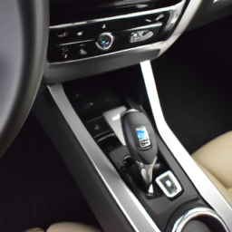
and test the shifter again. Make sure you can shift smoothly from “Park” to “Drive” or “Reverse” when the brake pedal is pressed.

### Additional Tips:
– If cleaning and inspecting don’t resolve the issue, you may need to replace the shift interlock solenoid or the entire shifter assembly. Consult your vehicle’s manual for specific part numbers and procedures.
– If you’re unsure at any step, it’s always best to consult a professional mechanic.

By following these steps, you should be able to address the shift interlock issue in your Mercedes Benz C-Class. Good luck with your repair!
An alarm system in a car is a sophisticated security device designed to deter theft and protect the vehicle and its contents. It typically consists of a series of sensors, an audible alarm, and a control unit that monitors the car for unauthorized access or suspicious activity. The primary function of an alarm system is to detect potential threats, such as attempted break-ins or tampering with the vehicle.

Most modern car alarm systems feature a combination of different sensors, including door sensors, motion detectors, and impact sensors. Door sensors are triggered when a door is opened without the proper key or remote, while motion detectors can sense movement within the cabin. Impact sensors respond to vibrations or shocks, such as someone attempting to break a window or tamper with the car’s exterior.

When the alarm system is triggered, it emits a loud siren or beep, alerting the owner and potentially scaring off thieves. Many systems also integrate with remote keyless entry, allowing the owner to arm or disarm the alarm from a distance. Some advanced alarm systems include GPS tracking, enabling owners to locate their vehicle in the event of theft.

Furthermore, modern car alarm systems can be connected to a smartphone app, providing real-time notifications and control over the alarm status. Overall, a car alarm system is an essential component of automotive security, enhancing the protection of both the vehicle and its occupants.