Download 1997 Renault Master II Service and Repair Manual –

owners manual
Drivetrain repair on a Renault Master II involves several key components and tools. click here for more details on the download manual…..


    WRECKING 2016 RENAULT MASTER 2.3 AUTOMATIC (C29721) EBAY STORE: http://bit.ly/EBAYSTOREJJ CALL: 02-9724-8099 EMAIL: sales@jjautoparts.com.au WEBSITE: …

    simulando ECU Renault Master CDI Este simulador você pode ligar qualquer ecu diesel 12v ou 24v, as ligações das ECUs são bem fáceis ( não precisa fazer um …

Below is a detailed guide using bullet points to outline the necessary tools and steps involved in the repair process.

### Tools Needed for Drivetrain Repair

– **Socket Set**
– A comprehensive metric socket set (including deep sockets) is essential for removing bolts on various drivetrain components.
– Ensure you have a ratchet handle and a breaker bar for added torque on stubborn nuts and bolts.

– **Wrenches**
– An adjustable wrench and a set of combination wrenches in metric sizes for accessing tight spaces and securing various components.

– **Torque Wrench**
– A torque wrench to ensure that bolts are tightened to the manufacturer’s specifications, which is crucial for safety and performance.

– **Pliers**
– Needle-nose and slip-joint pliers for gripping and maneuvering small components and clips.

– **Screwdrivers**
– A set of flathead and Phillips screwdrivers for removing screws from covers or securing components.

– **Pry Bar**
– A pry bar to help remove stubborn components or to pry apart parts that are stuck together.

– **Jack and Jack Stands**
– A hydraulic jack to lift the vehicle and jack stands for securely supporting it while you work underneath.

– **Transmission Fluid Pump**
– For draining and refilling transmission fluid if applicable.

– **Oil Catch Pan**
– To catch any fluids that may leak out during the repair process.

– **Cleaning Supplies**
– Degreaser and rags to clean parts before reassembly.

– **Replacement Parts**
– Gaskets, seals, bearings, or any other components specific to the drivetrain that need replacing.

– **Creeper or Mat**
– A mechanic’s creeper or mat for comfort while working underneath the vehicle.

### Steps for Drivetrain Repair

– **Diagnose the Issue**
– Check for symptoms such as unusual noises, vibrations, or fluid leaks. Verify the source of the issue, whether it’s related to the transmission, differential, or driveshaft.

– **Prepare the Vehicle**
– Park the Renault Master II on a flat, level surface. Engage the parking brake and place wheel chocks behind the rear wheels.
– Lift the front or rear of the vehicle using a hydraulic jack and secure it with jack stands.

– **Remove the Affected Components**
– Depending on the issue, remove the driveshaft by loosening the bolts at both the rear differential and transmission. Use the socket set and wrenches for this operation.
– If the transmission is involved, Disconnect any electrical connections, shift linkage, and fluid lines before removing it.

– **Inspect Components**
thoroughly inspect the driveshaft, universal joints, transmission, and differential for wear and damage.
– Check for play in the universal joints and any signs of leaking fluid.

– **Replace damaged Parts**
– Replace any worn or damaged components, such as universal joints, bearings, or seals. Ensure that new parts match the specifications for the Renault Master II.

– **Reassemble the Drivetrain**
– Reinstall the driveshaftdownload Renault Master II workshop manual and transmission securely. Ensure that all bolts are properly torqued using the torque wrench according to manufacturer specifications.
Reconnect any electrical connections and fluid lines that were disconnected.

– **Refill Fluids**
– If the transmission or differential was serviced, refill with the appropriate type of fluid using the transmission fluid pump.

– **Test the Vehicle**
– Lower the vehicle from the jack stands and start the engine. Test drive the vehicle to ensure that the issue has been resolved and that there are no new leaks or noises.

– **Final Inspection**
– After the test drive, perform a final inspection under the vehicle to check for any leaks or loose components.

### Safety Considerations

– Always wear appropriate safety gear, including gloves and safety glasses.
– Ensure the vehicle is securely lifted and supported before working underneath it.
– Dispose of any old fluids and parts in accordance with local regulations.

By following these steps and using the necessary tools, you can effectively carry out drivetrain repair on a Renault Master II.
A tow hook is a critical component found on vehicles, designed primarily for the purpose of towing or being towed. Typically made from durable materials such as steel or reinforced plastic, tow hooks are engineered to withstand significant stress and strain during towing operations. They are commonly located at the front or rear of a vehicle, allowing for versatility in towing situations, whether it be for recovering a stuck vehicle, transporting a disabled car, or assisting in off-road activities.

Tow hooks come in various designs, including fixed and detachable types. Fixed tow hooks are permanently mounted to the vehicle frame, providing a robust and reliable point for towing. Detachable hooks, on the other hand, can be removed when not in use, maintaining the vehicle’s aesthetic and aerodynamics. The installation of a tow hook is usually straightforward, often requiring specific mounting points on the vehicle’s chassis, ensuring that it is securely attached to handle the forces exerted during towing.

In addition to their functional role, tow hooks often adhere to industry standards for safety and performance, ensuring they can handle specific weight limits. They are particularly popular in off-road and motorsport applications, where the likelihood of vehicle recovery is higher. Overall, a tow hook is an essential accessory for any vehicle owner who may face situations requiring towing assistance, enhancing both safety and convenience on the road.

Download Daihatsu Boon 2004-2010 Workshop Repair Service Manual –

bookshop
Sure! click here for more details on the download manual…..


    Crash Test 2010 – 20** Toyota Passo / Daihatsu Boon / Sirion (Frontal Offset) JNCAP Overall Rating of 6 stars.

    Faisal Boon X4 Snf Ignition Track Day 2015 Sepang International Circuit Full track. #daihatsu #boon #x4 #gpstakhidup #wefie.

Replacing the brake lines on a Daihatsu Boon, or any vehicle, is a critical task that ensures your brakes work Safely and effectively. Here’s a step-by-step guide to help you understand the process, even if you have little mechanical experience. Always remember that if you’re unsure or uncomfortable, it’s best to have a professional handle it.

### Tools and Materials Needed:

1. **New brake lines** (specific to your Daihatsu Boon)
2. **Wrenches** (usually 10mm and 12mm, but check your vehicle)
3. **Brake fluid** (make sure it matches your vehicle’s specifications)
4. **Brake line cutter** (if needed)
5. **Flare nut wrench** (to avoid rounding off nuts)
6. **Basin or rag** (to catch any leaking brake fluid)
7. **Safety glasses and gloves** (for protection)
8. **Jack and jack stands** (to lift the vehicle safely)

### Step-by-Step Guide:

#### 1. **Safety First**
– Park the car on a level surface and engage the parking brake.
– Wear safety glasses and gloves to protect your eyes and skin.

#### 2. **Lift the Vehicle**
– Use a jack to lift the front or rear of the vehicle, depending on which brake lines you are replacing.
– Secure the vehicle with jack stands to prevent it from falling.

#### 3. **Locate the Brake Lines**
– Find the brake lines, which are usually metal tubes running from the brake master cylinder to each brake. They may be attached to the undercarriage with clips.

#### 4. **Clean the Area**
– Before you start disconnecting anything, clean the area around the brake line fittings to prevent dirt from entering the brake system.

#### 5. **Disconnect the Old Brake Line**
– Use the flare nut wrench to loosen the nuts at both ends of the brake line (one end at the brake caliper or wheel cylinder, the other at the master cylinder or junction block).
– Be cautious as some brake fluid may leak out. Use the basin or rag to catch any fluid.

#### 6. **Remove the Old Line**
– Once the nuts are loosened, carefully remove the old brake line. If it’s rusted or stuck, you may need to wiggle it gently or use a brake line cutter.

#### 7. **Install the New Brake Line**
– Take your new brake line and thread it into place, connecting it to the same points where the old line was attached.
tighten the nuts securely, but be careful not to over-tighten, as this can cause damage.

#### 8. **Bleed the Brakes**
– After installing the new line, you need to bleed the brakes to remove any air from the system.
this typically involves having someone pump the brake pedal while you opendownload Daihatsu Boon workshop manual and close the bleeder valve on the brake caliper or cylinder until no air bubbles come out (follow your vehicle’s specific bleeding procedure).

#### 9. **Check for Leaks**
– Once everything is tightened and bled, check for any leaks by pressing the brake pedal and inspecting the connections.

#### 10. **Lower the Vehicle**
– Remove the jack stands and lower the car back to the ground.

#### 11. **Test Drive**
– Before you drive normally, take a short test drive at low speeds to ensure the brakes are functioning properly.

### Tips:
– Always refer to your vehicle’s manual for specific details about brake line replacement.
– Brake fluid is corrosive, so clean any spills immediately.
– If you’re ever unsure, consult with a professional mechanic.

By following these steps, you can replace the brake lines on a Daihatsu Boon. However, the brakes are a crucial part of vehicle safety, so if you’re uncertain, seeking professional help is always a good choice!
The flywheel is a crucial component found in various types of machinery, most notably in internal combustion engines and manual transmission systems. Its primary function is to store rotational energy and help maintain a consistent speed during operation. The flywheel is typically a heavy, disc-shaped object that is mounted on the engine’s crankshaft.

In the context of an internal combustion engine, the flywheel serves several important purposes. First, it smooths out the power delivery of the engine by providing a reservoir of kinetic energy. As the engine cycles through its power strokes, the flywheel absorbs energy during the power stroke and releases it during other strokes, effectively minimizing fluctuations in power and helping to maintain a steady rotation. this results in a smoother operation, reducing vibrations and improving overall engine performance.

Additionally, the flywheel plays a vital role in the starting process of the engine. It is often equipped with a ring gear that engages the starter motor, allowing the engine to initiate combustion. In manual transmission vehicles, the flywheel also assists in the process of shifting gears by providing a stable surface for the clutch to engage and disengage.

Moreover, flywheels can also be utilized in various applications beyond automotive engines, including energy storage systems and industrial machinery, where they help manage energy inputs and outputs effectively. Overall, the flywheel is an essential component that greatly contributes to the efficiency, smoothness, and performance of engine operations.

Download Jeep Wrangler TJ 2000 2001 Workshop Repair Service Manual –

online
Replacing the anti-roll (sway) bar on a Jeep Wrangler TJ involves several steps and requires specific tools and equipment. click here for more details on the download manual…..


    Jeep Wrangler Common Rust Spots: TJ [Watch BEFORE You Buy] The Jeep Wrangler rusts super bad. Here’s what to look for to make sure your TJ Jeep is still roadworthy, structurally sound, and in …

    How To Replace The Power Steering Gear Box On A Jeep Wrangler Tj Brian Eslick from How to Automotive http://www.howtoautomotive.com takes you step-by-step through the process of replacing the …

Below are detailed instructions along with the necessary tools for the process.

### Tools and Equipment Needed

– **Jack and Jack Stands**
– Used to lift and secure the vehicle safely.

– **Socket Set (Metric)**
– Generally, sizes from 10mm to 18mm are required; ensure you have both deep and shallow sockets.

– **Wrench Set**
– A set of open-end and box wrenches can be helpful for accessing tight spaces.

– **Torque Wrench**
– Essential for ensuring that bolts are tightened to the manufacturer’s specifications.

– **Pry Bar**
– Useful for removing stubborn parts or providing leverage.

– **Hammer**
– May be needed to tap out bolts or sway bar links that are stuck.

– **PB Blaster or Penetrating Oil**
– To help loosen any rusted or seized bolts.

– **Safety Glasses and Gloves**
– Personal protective equipment to protect your eyes and hands during the process.

### Replacement Steps

– **Preparation**
– Park the Jeep on a level surface and engage the parking brake to prevent movement.
– Wear safety glasses and gloves for protection.

– **Lifting the Vehicle**
– Use a jack to lift the front of the Jeep.
– Secure the vehicle with jack stands under the frame, ensuring it is stable and safe to work under.

– **Removing the Wheels (Optional)**
– For better access, you may choose to remove the front wheels using a socket and wrench. This step is optional but can make the job easier.

– **Inspect the Existing Sway Bar**
– Before removal, inspect the sway bar, links, and bushings for wear. This will help determine if you need to replace other components as well.

– **Loosening the Sway Bar Links**
– Locate the sway bar links, which connect the sway bar to the control arms.
– Apply penetrating oil to the bolts if they appear rusted. Allow it to soak for a few minutes.
– Using the appropriate socket or wrench, loosen and remove the nuts on both ends of the sway bar links.

– **Removing the Sway Bar Bushings**
– Locate the sway bar bushings that secure the sway bar to the frame.
– Use a socket and wrench to remove the bolts securing the bushings. There may be two bolts for each bushing.
– Once the bolts are removed, slide the sway bar out of the bushings.

– **Removing the Sway Bar**
– With the links and bushings removed, carefully slide the sway bar out from the vehicle.
– If it is stuck, use a pry bar to gently coax it out.

– **Installing the New Sway Bar**
– Take the new sway bar and position it in the same orientation as the old one.
– Slide the sway bar into the bushings, ensuring it fits snugly.

– **Securing the Sway Bar Bushings**
– Reinstall the bolts for the sway bar bushings using the socket and wrench.
– Tighten them to the manufacturer’s specified torque settings.

– **Reattaching the Sway Bar Links**
– Align the sway bar with the control armsdownload Jeep Wrangler TJ workshop manual and reattach the sway bar links.
– Ensure the links are oriented correctly and secure them with the nuts.
– Tighten the nuts to the manufacturer’s specified torque.

– **Rechecking All Connections**
– Go through all the bolts and nuts to ensure everything is secured properly.
– Double-check that the sway bar is properly aligned and not obstructing any components.

– **Reinstalling Wheels (If Removed)**
– If you removed the wheels, reinstall them and tighten the lug nuts in a star pattern to ensure even pressure.

– **Lowering the Vehicle**
– Carefully lower the Jeep back to the ground using the jack, and remove the jack stands.

– **Final Inspection**
– Once the vehicle is back on the ground, perform a final inspection to ensure all components are properly secured and nothing is loose.

### Conclusion

Replacing the anti-roll bar on a Jeep Wrangler TJ can be a straightforward process if you follow these steps and use the right tools. Always refer to a service manual for specific torque specifications and guidelines for your model, and if in doubt, consult a professional mechanic.
The transmission fluid dipstick is a crucial component in automatic transmission systems, serving as an indicator of the transmission fluid level and its condition. Typically made of metal or durable plastic, the dipstick is designed to be easily accessible, allowing vehicle owners and mechanics to perform routine checks without extensive disassembly.

Located within the engine compartment, the transmission fluid dipstick is usually marked with a brightly colored handle for easy identification. It features a long, slender shaft that extends into the transmission fluid reservoir. when checking the fluid, the dipstick is removed, wiped clean to remove any residue, and then reinserted to gauge the fluid level. The dipstick is marked with indicators that show the acceptable range for fluid levels—usually marked as “full” and “add”—which helps determine if the fluid needs to be topped off.

In addition to measuring fluid levels, the dipstick can also provide insight into the fluid’s condition. Healthy transmission fluid typically appears red and clear, whereas dark or burnt-smelling fluid may indicate a need for a fluid change or potential transmission issues. Regularly checking the transmission fluid using the dipstick is essential for maintaining the health and longevity of the transmission system, as proper fluid levels and quality are vital for smooth operation and efficient gear shifting. Neglecting this component can lead to transmission overheating, poor performance, and ultimately, costly repairs.

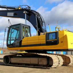
Download Volvo ECR145CL Excavator Service Repair Shop Manual –

owners manual
Replacing the clutch slave cylinder on a Volvo ECR145CL excavator involves several steps to ensure proper installation and functionality. click here for more details on the download manual…..


    2011 Volvo ECR145CL Hydraulic Excavator at Auction Check out this 2011 Volvo ECR145CL Hydraulic Excavator at auction on 5/28. You can find more details and a full list of auction …

Here’s a reverse order explanation of the procedure:

### 7. **Reassemble and Test**
– **Reconnect the Battery**: Reattach the battery terminals, ensuring a secure connection.
– **Test the Clutch**: Start the engine and test the clutch operation to ensure it engages and disengages smoothly.
– **Check for Leaks**: Inspect the area around the clutch slave cylinder for any signs of fluid leaks.

### 6. **Install the New Clutch Slave Cylinder**
– **Position the New Cylinder**: Align the new slave cylinder with the mounting points.
– **Secure the Cylinder**: Fasten it in place using the previously removed bolts or nuts.
– **Reconnect hydraulic Line**: attach the hydraulic line to the slave cylinder, ensuring it’s tightened securely.

### 5. **Remove the Old Clutch Slave Cylinder**
– **Disconnect hydraulic Line**: Carefully detach the hydraulic line from the old slave cylinder, and be prepared for some fluid to leak out.
– **Unbolt the Cylinder**: Remove the bolts or nuts securing the old slave cylinder to the mounting bracket.

### 4. **Prepare the Work Area**
– **Gather Tools and Parts**: Have all necessary tools (wrenches, sockets, etc.) and the new clutch slave cylinder ready.
– **Ensure Safety**: Use safety goggles and gloves, and ensure the excavator is on a level surface and securely supported.

### 3. **Access the Clutch Slave Cylinder**
– **Remove Any Obstructions**: Take off any panels or components that may be blocking access to the clutch slave cylinder.
– **Locate the Slave Cylinder**: Identify the position of the clutch slave cylinder on the excavator.

### 2. **Disconnect Power Supply**
– **Turn Off the Excavator**: Ensure the excavator is turned off and cool before starting the procedure.
– **Disconnect the Battery**: Remove the negative terminal from the battery to prevent any electrical issues.

### 1. **Preparation Before Starting**
– **Refer to Service Manual**: Always consult the Volvo ECR145CL excavator service manual for specific instructionsdownload Volvo ECR145CL Excavator Shop workshop manual and torque specifications related to the clutch slave cylinder replacement.

Following these steps in reverse order will give you a clearer understanding of the clutch slave cylinder replacement process. Always prioritize safety and consult the service manual for detailed instructions tailored to your specific excavator model.
A wheel bearing is a crucial component of a vehicle’s wheel assembly, designed to facilitate smooth rotation of the wheel while supporting the vehicle’s weight. It consists of a set of steel balls or rollers encased in a metal housing, known as the race. These bearings are strategically positioned between the wheel hub and the axle, allowing the wheel to spin freely with minimal friction.

Wheel bearings play a vital role in the overall performance and safety of a vehicle. They are subjected to substantial loads and forces, as they bear the weight of the vehicle and endure the stresses of acceleration, braking, and cornering. High-quality wheel bearings are engineered to withstand these forces, ensuring durability and longevity.

Over time, wheel bearings can wear out due to factors such as exposure to moisture, dirt, and road debris, which can lead to rust and degradation. Symptoms of a failing wheel bearing may include unusual noises, such as grinding or humming sounds, as well as vibrations or a noticeable change in handling. If left unaddressed, a failed wheel bearing can lead to more severe issues, including wheel separation, posing a significant safety risk.

Regular maintenance and inspection of wheel bearings are essential, especially in high-mileage vehicles, to ensure optimal performance and safety on the road.

Download 2004 JEEP WRANGLER TJ Service and Repair Manual –

australian
Repairing a windshield on a Jeep Wrangler TJ can seem daunting, but with some basic tools and careful steps, you can do it yourself! click here for more details on the download manual…..


    Jeep tj master cylinder upgrade to d3500 Hey it’s tank, at tanks tips. I break down and show you everything going into some of the best mods for Jeep tj 97-06 wranglers.

    8 THINGS EVERY JEEP TJ OWNER SHOULD KNOW (Most Common Questions) In This Video I Cover Some Of The Most Common Jeep TJ Questions Asked Constantly In Forums, Facebook Groups, and …

Here’s a simple guide to help you through the process.

### Tools and materials Needed:
1. **Replacement Windshield**: Make sure it’s the right size for your Jeep Wrangler TJ.
2. **Windshield Adhesive**: This is a special glue designed for windshields.
3. **Utility Knife**: To cut old adhesive.
4. **Trim Removal Tool**: To remove any molding or trim around the windshield.
5. **Screwdriver**: For any screws holding the windshield frame.
6. **Rags**: To clean surfaces.
7. **Safety Glasses and Gloves**: To protect yourself.

### Steps to Replace the Windshield:

1. **Preparation**:
– Ensure you have a clean, dry workspace and gather all your tools and materials.
– Wear safety glasses and gloves to protect yourself from any sharp glass.

2. **Remove the Old Windshield**:
– Carefully inspect how the windshield is held in place. Look for any screws or clips that need to be removed.
– Use the trim removal tool to gently pry off any molding around the windshield. Be careful not to damage the trim, as you may want to reuse it.
– With the utility knife, cut through the adhesive around the edges of the windshield. Be careful not to cut too deep, as you could damage the Jeep’s frame.

3. **Take Out the Windshield**:
– Once the adhesive is cut, gently push from the inside of the vehicle to remove the windshield. You may need a helper for this step, as windshields can be heavy and awkward to handle.
– Make sure to set the old windshield aside safely to avoid any accidents.

4. **Clean the Frame**:
– Use a rag to wipe down the area where the new windshield will sit. Remove any old adhesive and ensure the surface is clean and smooth.

5. **Apply New Adhesive**:
– Follow the instructions on the windshield adhesive tube. Apply a continuous bead of adhesive around the edge of the frame where the windshield will sit.

6. **Install the New Windshield**:
– With the help of a friend, carefully lift the new windshield into place. Align it properly and press it down into the adhesive. Make sure it’s seated evenly all the way around.
– If your Jeep has molding, replace it now.

7. **Cure Time**:
– Allow the adhesive to cure as per the manufacturer’s instructions, which can take several hours. Avoid driving the Jeep during this time to ensure the windshield sets properly.

8. **Final Checks**:
– Once the adhesive has cured, check that everything is securely in place. You can clean the glass insidedownload JEEP WRANGLER TJ workshop manual and out for a clear view.

### Important Tips:
– Always read the instructions on any products you use, especially the adhesive.
– If you’re unsure about any step, it might be worth consulting a professional.
– Be careful when handling glass to avoid injury.

And there you have it! With patience and careful work, you can successfully replace the windshield on your Jeep Wrangler TJ. Good luck!
The shift cable is a critical component of the vehicle’s transmission system, responsible for linking the gear shifter (located in the cabin) to the transmission itself. This cable serves as a conduit for the driver’s input, translating the movement of the shifter into corresponding actions within the transmission, which ultimately engages the desired gear.

Typically made from durable materials such as steel or a high-strength polymer, shift cables are designed to withstand the stresses of repeated use, as well as the environmental factors present in the engine compartment, such as heat and vibration. The shift cable is usually encased in a protective sheath to prevent wear and tear, ensuring longevity and reliability.

In automatic transmissions, the shift cable connects the gear selector to the transmission control lever, allowing the driver to select different modes such as park, reverse, neutral, and drive. In manual transmissions, the cable operates similarly, allowing the driver to shift gears via the clutch pedal and gear lever.

Over time, shift cables can experience wear, fraying, or other forms of damage, leading to issues such as difficulty in changing gears, misalignment, or even complete failure to engage a gear. Regular maintenance checks are essential to ensure the functionality of the shift cable, as a malfunction can significantly impact the vehicle’s drivability and safety.

Download Volkswagen Jetta 1.8L turbo 1999-2005 Service Manual –

discount
Replacing the transmission pan gasket on a Volkswagen Jetta 1.8L Turbo involves several steps and requires specific tools and components. click here for more details on the download manual…..


    Jetta 1.8 turbo gt28 420 whp

    Volkswagen/Audi 1.8t Engine Diagnostic & Maintenance Guide (Mk4 Golf, Jetta, New Beetle, Audi… The Volkswagen & Audi 1.8t engine was found in numerous cars across the VW and Audi lineup, from the VW Golf to the …

Below is a detailed guide to help you through the process.

### Tools and Materials Needed:

1. **Tools:**
– Socket set (including 10mm and 13mm sockets)
– Ratchet and extension
– Torque wrench
– Screwdrivers (flat and Phillips)
– Pliers
– Oil catch pan
– Funnel
– Brush or scraper for cleaning
– Clean rags or shop towels
– Safety glasses and gloves

2. **Materials:**
– New transmission pan gasket (OEM recommended)
– New transmission fluid (refer to your owner’s manual for specifications)
– RTV silicone (if recommended)
– Brake cleaner (for cleaning surfaces)
– Shop towels

### Preparation:

1. **Safety First:**
– Park the vehicle on a level surface and engage the parking brake.
– Wear safety glasses and gloves for protection.

2. **Lift the Vehicle:**
– Use a jack to lift the front of the vehicle and secure it with jack stands. Ensure the vehicle is stable before working underneath.

3. **Drain the Transmission Fluid:**
– Place an oil catch pan under the transmission pan.
– Remove the drain plug (if equipped) with the correct socket and allow the fluid to drain completely. If there is no drain plug, you may have to remove the pan to drain the fluid.

### Removing the Transmission Pan:

1. **Remove the Transmission Pan Bolts:**
– Use the socket and ratchet to remove the bolts securing the transmission pan. These are typically 10mm or 13mm bolts.
– Work your way around the pan, loosening bolts in a cross pattern to prevent bending the pan.

2. **Take Off the Transmission Pan:**
– Gently pry the pan off using a flat screwdriver if it’s stuck. Take care not to damage the pan or the transmission housing.
– Allow any remaining fluid to drain out into the oil catch pan.

### Cleaning the Components:

1. **Clean the Pan:**
– Use a brush or scraper to remove any old gasket material from the pan and the transmission housing. Be cautious not to scratch the surfaces.
– Clean the inside of the pan and remove any debris or metal shavings.
– Use brake cleaner to wipe down the pan and transmission mating surfaces.

2. **Inspect the Pan:**
– Check the transmission pan for any signs of damage or wear. If it’s severely damaged, consider replacing it.

### Installing the New Gasket:

1. **Position the New Gasket:**
– Place the new transmission pan gasket onto the clean transmission housing. Make sure it fits snugly and aligns with the bolt holes.

2. **Apply RTV Silicone (if necessary):**
– If the manufacturer recommends it, apply a thin bead of RTV silicone on the transmission housing where the gasket will sit. This helps create a better seal.

### Reinstalling the Transmission Pan:

1. **Reattach the Transmission Pan:**
– Carefully position the transmission pan back onto the transmission, ensuring the gasket stays in place.
– Hand-tighten the bolts in a cross pattern to ensure even pressure on the gasket.

2. **Torque the Bolts:**
– Using a torque wrench, tighten the bolts to the manufacturer’s specified torque (usually around 8-10 ft-lbs, but check your service manual for the exact specification).
– Follow a crisscross pattern when torquing the bolts.

### Refilling Transmission Fluid:

1. **Reinstall the Drain Plug (if removed):**
– If you removed the drain plug, reinstall itdownload Volkswagen Jetta 1.8L turbo workshop manual and torque it to the specified value.

2. **Refill Transmission Fluid:**
– Locate the transmission fluid dipstick or fill plug (depending on your model).
– Use a funnel to pour the new transmission fluid into the transmission. Refer to your owner’s manual for the correct type and amount of fluid.
– Check the level using the dipstick after adding fluid.

### Final Steps:

1. **Check for Leaks:**
– Start the engine and let it run for a few minutes. Shift through the gears while holding the brake pedal to circulate the fluid.
– Check underneath the vehicle for any fluid leaks.

2. **Dispose of Old Fluid:**
– Properly dispose of the old transmission fluid and any used materials at a recycling center or an appropriate disposal location.

3. **Lower the Vehicle:**
– Once everything is checked and secure, lower the vehicle back to the ground.

### Conclusion:

Replacing the transmission pan gasket on a Volkswagen Jetta 1.8L Turbo is a moderately complex task that requires attention to detail. Following the steps outlined above will help ensure a successful gasket replacement and contribute to the longevity of your vehicle’s transmission system. Always consult your vehicle’s service manual for specific torque values and additional details related to your model.
The Positive Crankcase Ventilation (PCV) valve is a crucial component of an automobile’s engine system, designed to manage the pressure and emissions within the crankcase. It plays a vital role in the overall efficiency and environmental performance of an internal combustion engine. The PCV system was developed to reduce harmful emissions and improve engine performance by recycling gases that would otherwise escape into the atmosphere.

The primary function of the PCV valve is to allow gases that accumulate in the crankcase—such as unburned fuel, oil vapors, and combustion byproducts—to be drawn back into the intake manifold, where they can be re-burned in the engine. This process not only minimizes the release of harmful pollutants but also helps to maintain optimal pressure within the crankcase, preventing oil leaks and other engine issues.

Typically made of plastic or metal, the PCV valve operates based on engine vacuum. When the engine is running, the valve opens and closes in response to changes in pressure and airflow, ensuring that only the appropriate amount of gases is recycled. A malfunctioning PCV valve can lead to various problems, including increased oil consumption, engine knocking, or reduced engine performance. Regular inspection and maintenance of the PCV valve are essential to ensure the engine runs efficiently and meets emissions standards.

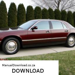
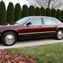
Download 2007 GRand MARQUIS Service and Repair Manual –

online
Replacing the anti-roll bar (also known as a sway bar) on a Mercury Grand Marquis involves several steps, tools, and safety precautions. click here for more details on the download manual…..


    $400 Beater FUTURE Enduro RACE CAR — Mercury Grand Marquis — Will it Drive Home? Can We Break… Due to your response on the blue station wagon video, I picked up this pile of garbage Mercury Grand Marquis to go Enduro …

    Panther Platform: Where to look for RUST and ROT! Crown Vic, Grand Marquis, Town Car This is a quick video on where to look for rust and rot on a panther platform car. This mostly applies to vehicles exposed to road …

The anti-roll bar helps reduce body roll during cornering by linking the left and right wheels. Below is a detailed guide to replacing the anti-roll bar, including descriptions of every component involved in the process.

### Tools and Materials Needed:

1. **Tools:**
– Floor jack
– Jack stands
– Socket set (including ratchet and extensions)
– Wrenches (metric and standard)
– Torque wrench
– Breaker bar (optional)
– Pliers
– Hammer
– Pry bar (optional)
– Lubricant (penetrating oil)

2. **Replacement Parts:**
– New anti-roll bar (sway bar)
– New sway bar bushings
– New sway bar end links (if necessary)
– New hardware (bolts, nuts, washers if required)

### Safety Precautions:

– Work on a flat, stable surface.
– Use wheel chocks to prevent the vehicle from rolling.
– Always wear safety glasses and gloves.
– Make sure the vehicle is securely supported on jack stands before working under it.

### Step-by-Step Replacement Process:

#### 1. **Preparation:**
– Park the vehicle on a level surface and turn off the ignition.
– Open the hood and disconnect the negative battery terminal to avoid any electrical issues.

#### 2. **Lifting the Vehicle:**
– Use a floor jack to lift the front of the vehicle.
– Secure the vehicle on jack stands to ensure safety while working underneath.

#### 3. **Remove the Wheels:**
– Loosen the lug nuts on the front wheels using a lug wrench.
– Remove the lug nuts and take off the front wheels to access the sway bar.

#### 4. **Locate the Anti-Roll Bar:**
– The anti-roll bar is typically located under the front of the vehicle, running parallel to the ground, connecting the left and right suspension components.

#### 5. **Remove the Sway Bar End Links:**
– Identify the sway bar end links, which connect the anti-roll bar to the suspension components.
– Use a socket wrench to remove the nuts securing the end links to the anti-roll bar and the lower control arm.
– If the end links are rusted or damaged, you may need to use penetrating oil and a hammer to loosen them.

#### 6. **Remove the Sway Bar Bushings:**
– Locate the sway bar bushings that secure the anti-roll bar to the vehicle’s frame. They are generally held in place with bolts.
– Use a socket wrench to remove the bolts securing the bushings.
– Carefully slide the bushings off the bar.

#### 7. **Remove the Anti-Roll Bar:**
– With the end links and bushings removed, you can now remove the sway bar from its mounting points.
– Gently maneuver the sway bar out of its position. Be cautious of any other components that may be in the way.

#### 8. **Install the New Anti-Roll Bar:**
– Position the new anti-roll bar in place, ensuring it is correctly aligned with the mounting points.
reinstall the sway bar bushings onto the new bardownload GRand MARQUIS workshop manual and secure them with the bolts. Make sure to torque them to the manufacturer’s specifications.

#### 9. **Reinstall the Sway Bar End Links:**
– Attach the end links to the anti-roll bar and the lower control arms.
– Use a torque wrench to tighten the nuts to the recommended torque specifications.

#### 10. **Reinstall the Wheels:**
– Reattach the front wheels and hand-tighten the lug nuts.
– Lower the vehicle back to the ground using the floor jack.

#### 11. **Tighten the Lug Nuts:**
– Once on the ground, use a torque wrench to tighten the lug nuts to the specified torque.

#### 12. **Reconnect the Battery:**
– Reconnect the negative battery terminal.

#### 13. **Test Drive:**
– Take the vehicle for a test drive to ensure that everything is functioning correctly and to check for any unusual noises.

### Conclusion:
Replacing the anti-roll bar in a Mercury Grand Marquis is a straightforward but essential maintenance task that can enhance the vehicle’s handling and stability. Ensure that you follow all safety precautions and torque specifications for a successful replacement. If you encounter any difficulties, consider seeking assistance from a professional mechanic.
The windshield wiper is a crucial component of a vehicle’s safety and visibility system, designed to remove rain, snow, and debris from the windshield to ensure a clear line of sight for the driver. Typically made up of a wiper arm and a rubber wiper blade, the system operates by utilizing a motor that moves the wiper arm back and forth across the glass surface. This motion effectively sweeps away moisture and contaminants, improving visibility during adverse weather conditions.

Windshield wipers are equipped with various settings, allowing the driver to adjust the frequency and speed of the wiping action according to the intensity of precipitation. Most vehicles come with a standard two-speed setting: a slower speed for light rain and a faster one for heavier downpours. many modern vehicles also feature intermittent wipers, which allow the driver to set a delay between wipes, providing greater control during varying weather conditions.

The materials used in wiper blades have evolved over time, with many now utilizing synthetic rubber or silicone, which enhance durability and performance compared to traditional rubber. Regular maintenance of windshield wipers is essential, as worn or damaged blades can lead to streaking, reduced visibility, and potential safety hazards. Overall, windshield wipers play an indispensable role in ensuring safe driving conditions, especially in inclement weather.

Download 1989 Suzuki Swift 1300 GTI Service Repair Workshop Manual –

buy
Repairing the suspension strut tower on a Suzuki Swift 1300 GTI is a task that requires mechanical knowledge, appropriate tools, and safety precautions. click here for more details on the download manual…..


    Suzuki swift cultus Gti engine rebuild Turbo overall rebuild turbo drift gt swift geo metro.

    Clutch Release bearing / Throw out Bearing Explained – How it works? A quick look at what the clutch release/throw-out bearing is, what it does and how it works. In this particular video we are using a …

The strut tower is a structural component that supports the upper end of the suspension strut and is crucial for the vehicle’s stability and handling. Damage to the strut tower can lead to handling issues, excessive tire wear, and alignment problems. Here’s a detailed guide on how to perform the repair:

### Tools and Materials Needed:

1. **Tools:**
– Socket set (metric)
– Wrenches (metric)
– Torque wrench
screwdrivers (flathead and Phillips)
– Pry bar
– Hammer
– Jack and jack stands
– Suspension spring compressor
– Cutting tool (if necessary)
– Welding equipment (if necessary)
– Grinder (if necessary)
– Paint and rust inhibitor (for protection after repair)

2. **Materials:**
– Replacement strut tower (if damaged beyond repair)
– Reinforcement plates (if required)
– Weld rods (for welding)
– Primer and paint (for corrosion protection)
– Anti-seize compound

### Safety Precautions:
– Always wear safety goggles and gloves.
– Ensure the vehicle is on a flat surface and use wheel chocks.
– Never work under a vehicle supported only by a jack; always use jack stands.

### Step-by-Step Procedure:

#### 1. Preparation
– **Park the Vehicle:** Ensure the vehicle is on a level surface.
– **Disconnect the Battery:** remove the negative terminal to prevent any electrical issues.

#### 2. remove the Front Struts
– **Lift the Vehicle:** Use a jack to lift the front of the vehicle and place it securely on jack stands.
– **Remove the Wheel:** Take off the front wheel to access the strut assembly.

#### 3. Detach the Strut Assembly
– **Unbolt the Strut:** Use the socket set to remove the bolts securing the strut to the steering knuckle and the upper strut mount in the engine bay.
– **Remove the Strut:** Carefully pull the strut out of the strut tower.

#### 4. Inspect the Strut Tower
– **Examine the Damage:** Check for rust, cracks, or any signs of structural failure. Use a wire brush to clean the area around the strut tower to properly assess the damage.

#### 5. Repair or Replace the Strut Tower
– **Minor Repairs (e.g., rust):**
– **Grind the Area:** Use a grinder to remove rust and debris from the damaged area.
– **Weld Reinforcement Plates:** If the area is thin but not completely compromised, cut reinforcement plates from sheet metal and weld them over the damaged area.

– **Major Repairs (e.g., cracks):**
– **Remove Damaged Section:** If the strut tower is extensively damaged, a portion may need to be cut out. Use a cutting tool to carefully remove the compromised section.
– **Fabricate New Section:** Cut a new piece of metal to fit the removed section, ensuring it matches the original structure.
– **Weld New Metal:** Weld the new piece into place, ensuring strong, even welds to restore structural integrity.

#### 6. Finish the Repair
– **Cleandownload Suzuki Swift 1300 GTI workshop manual and Paint:** Once the repair is complete, clean the area and apply a rust-inhibiting primer followed by paint to protect against future corrosion.
– **Allow to Cure:** Let the paint cure properly before reassembling the suspension components.

#### 7. Reassemble the Strut Assembly
– **Install the Strut:** place the strut back into the strut tower, ensuring it is seated properly.
– **Bolt the Strut:** Reattach the strut to the steering knuckle and secure it to the upper mount with the appropriate torque specifications.

#### 8. Reinstall the Wheel
– **Put the Wheel Back On:** Reinstall the wheel and hand-tighten the lug nuts.

#### 9. Lower the Vehicle
– **Remove Jack Stands:** Carefully lower the vehicle back to the ground.
– **Tighten Lug Nuts:** Once on the ground, fully tighten the lug nuts in a crisscross pattern to ensure even pressure.

#### 10. Final Checks
– **Reconnect the Battery:** Reattach the negative battery terminal.
– **Test Drive:** Take the vehicle for a short test drive to ensure everything is functioning correctly and there are no unusual noises or handling issues.

### Conclusion
Repairing the suspension strut tower on your Suzuki Swift 1300 GTI can be a complex task, especially if extensive damage is present. If you are not confident in your ability to perform these repairs, it is advisable to consult with or hire a professional mechanic. Always prioritize safety and proper techniques to ensure the integrity of your vehicle’s suspension system.
The transmission dipstick is a crucial component in many vehicles, particularly those equipped with automatic transmissions. It serves as a simple yet effective tool for monitoring the level and condition of the transmission fluid, which is essential for the proper functioning of the transmission system. Typically made of metal or plastic, the dipstick is marked with specific measurements to indicate the appropriate fluid level, allowing drivers and mechanics to assess whether the transmission fluid is within the recommended range.

The dipstick usually features a brightly colored handle for easy identification, and it is inserted into a designated tube that leads to the transmission fluid reservoir. To check the fluid level, an individual needs to remove the dipstick, wipe it clean with a lint-free cloth, reinsert it back into the tube, and then pull it out again to observe the fluid level on the marked measurements. This process can also include checking the fluid’s condition, as healthy transmission fluid typically appears clear or slightly reddish. If the fluid is dark, gritty, or has a burnt odor, it may indicate contamination or degradation, necessitating a fluid change.

Maintaining the correct transmission fluid level is vital, as inadequate fluid can lead to overheating, poor shifting performance, and potential transmission failure. Therefore, regular checks using the transmission dipstick are an important part of vehicle maintenance, helping to ensure optimal performance and longevity of the transmission system.

Download 1999 BMW Z3 Service and Repair Manual –

bookstore
If you’re experiencing a Check Engine light on your BMW Z3 and want to troubleshoot the issue, here’s a step-by-step guide in reverse order: ### 10. click here for more details on the download manual…..


    What's in My Emergency Tool Kit- BMW Z3! What’s in the bag? Let me show you what’s in my emergency tool kit in New Blue, my BMW Z3. Wrenches, screwdrivers, Torx and …

    TOP 10 BMW Wheels for the Z3! We review the top 10 wheels for the BMW Z3, plus not one, not two, but three Zeds of the week! Check it out and see if your …

If you’re experiencing a check Engine light on your BMW Z3 and want to troubleshoot the issue, here’s a step-by-step guide in reverse order:

### 10. **Reset the check Engine Light (if applicable)**
– After addressing the issue, you can reset the check Engine light using an OBD-II scanner or by disconnecting the battery for a few minutes. If the light returns, the problem may still exist.

### 9. **Review Diagnostic Trouble Codes (DTCs)**
– Use an OBD-II scanner to read the codes stored in the vehicle’s computer. This will give you insight into what issues the engine management system has detected.

### 8. **Inspect for Obvious Issues**
– Look for any visible signs of trouble, such as loose or damaged wires, vacuum leaks, or a disconnected sensor. Sometimes, a simple visual inspection can reveal the problem.

### 7. **Check Engine Components**
– Inspect key components such as the fuel cap (make sure it’s tight), spark plugs, ignition coils, and air filters to identify any obvious wear or damage.

### 6. **Test the Battery and Alternator**
– A weak battery or faulty alternator can trigger the check Engine light. Ensure that the battery is charged and the alternator is functioning properly.

### 5. **Look for Recalls or Technical Service Bulletins (TSBs)**
check if there are any recalls or TSBs related to your vehicle’s model that might explain the check Engine light.

### 4. **Consult the Owner’s Manual**
– Refer to the BMW Z3 owner’s manual for specific information regarding the check Engine light and potential issues related to it.

### 3. **Consider Recent Changes or Repairs**
– Think back to any recent repairs or changes made to the vehicle. Sometimes, a new part or service can inadvertently cause the light to come on.

### 2. **Drive Cycle**
– If the check Engine light is intermittent, drive the vehicle for a while to see if the light resets itself. Sometimes, minor issues can resolve after normal operation.

### 1. **Gather Toolsdownload BMW Z3 workshop manual and Prepare for Diagnostics**
– Before starting, gather necessary tools, including an OBD-II scanner, basic hand tools, and any replacement parts you might need for repairs.

By following these steps in reverse order, you can methodically address the check Engine light issue on your BMW Z3.
The blower fan resistor is a crucial component in a vehicle’s heating, ventilation, and air conditioning (HVAC) system. Its primary function is to regulate the speed of the blower motor, which is responsible for circulating air throughout the cabin. By adjusting the electrical resistance, the resistor allows the blower motor to operate at different speeds, enabling the driver and passengers to customize the airflow according to their comfort needs.

Typically located within the blower motor assembly or close to it, the blower fan resistor consists of a series of resistors that manage the voltage sent to the blower motor. When the vehicle’s HVAC system is activated, the resistor modulates the amount of voltage supplied to the motor, effectively controlling its speed. For instance, a higher resistance will result in a lower speed, while reduced resistance will allow for a higher speed.

One common issue with blower fan resistors is overheating, which can lead to failure. This often occurs due to prolonged usage at high speeds or if the resistor is exposed to moisture or dirt. Symptoms of a failing blower fan resistor may include the blower motor only working on certain speeds or completely ceasing to operate. Replacement is typically straightforward, making it an important component for ensuring optimal cabin comfort and air quality in a vehicle. Proper functioning of the blower fan resistor is essential for an effective HVAC system, ultimately contributing to a more pleasant driving experience.

Download 2008 GEM e2 GEM e4 GEM e6 GEM eS GEM eL GEM eL XD Service Ma –

bookstore
Replacing the shock absorbers on a GEM (Global Electric Motorcars) vehicle, such as the e2, e4, e6, eS, eL, or eL XD, involves several steps and requires specific tools and components. click here for more details on the download manual…..


    Caro-Kann's Two Knights Attack Miniature: So – Melkumyan In this game, Wesley demonstrated how White can use the Two Knights Attack variation of the Caro-Kann Defense to put …

    GEM el XD Walkaround Welcome to GEM of Miami, the region’s largest stocking Polaris GEM dealer. GEM of Miami is the premier Factory Authorized …

Below is a detailed guide on how to perform this replacement:

### Tools and Materials Needed

1. **Tools:**
– **Socket Set**: Usually metric sizes (10mm, 12mm, 14mm, etc.)
– **Wrenches**: Open-end or adjustable wrenches.
– **Torque Wrench**: For tightening bolts to manufacturer specifications.
– **Jack and Jack Stands**: To lift the vehicle safely.
– **Pliers**: For removing clips or retaining rings if necessary.
– **Hammer**: To help remove stubborn bolts or components.
– **Safety Glasses**: To protect your eyes during the process.
– **Gloves**: To protect your hands.
– **Brake Cleaner**: To clean any parts as needed.
– **Lubricant**: For bolts and bushings.

2. **Materials:**
– **Replacement Shock Absorbers**: Make sure to get the correct type for your specific GEM model.
– **Bushings and Mounting Hardware**: If the old ones are worn out, it’s a good idea to replace these as well.

### Steps for Shock Absorber Replacement

1. **Preparation:**
– Make sure the vehicle is parked on a flat surface.
– Turn off the vehicle and engage the parking brake.
– Gather all tools and materials needed for the job.

2. **Lifting the Vehicle:**
– Use a jack to lift the rear (or front, depending on which shocks you are replacing) of the GEM vehicle.
– Secure the vehicle with jack stands to ensure safety while you work.

3. **Removing the Old Shock Absorber:**
– **Locate the Shock Absorber**: Identify the position of the shock absorbers—one is typically mounted vertically at each wheel assembly.
– **Remove the lower Bolt**: Using the socket set, remove the lower mounting bolt of the shock absorber. Depending on the setup, you may need to hold the shock body with a wrench to prevent it from spinning.
– **Remove the Upper Bolt**: Next, locate the upper mounting bolt. This may require removing any cover panels or components obstructing access. Use the socket set to remove this bolt as well.
– **Take Out the Shock Absorber**: Once both bolts are removed, carefully slide the shock absorber out of its mountings. It may be necessary to wiggle it a bit to free it.

4. **Preparing the New Shock Absorber:**
– **Inspect New Part**: Before installation, inspect the new shock absorber for any damage and ensure it matches the old one.
– **Lubricate Bushings**: If the new shock comes with bushings, apply some lubricant to them for easier installation.

5. **Installing the New Shock Absorber:**
– **Position the New Shock**: Align the new shock absorber in the same position as the old one. Ensure it fits snugly into the mounting points.
– **Insert Upper Bolt**: Start with the upper mounting bolt. Insert it through the shock mount and thread it into the frame or bracket. Do not fully tighten yet.
– **Insert lower Bolt**: Next, push the bottom of the shock into its mountdownload GEM e2 GEM e4 GEM e6 GEM eS GEM eL GEM eL XD Ma workshop manual and insert the lower bolt. Again, thread it in but do not fully tighten yet.

6. **Tightening the Bolts:**
– Using the torque wrench, tighten the upper and lower bolts to the manufacturer’s specified torque settings. This information can usually be found in the vehicle’s service manual.

7. **Rechecking Installation:**
– Once both bolts are secured, double-check that everything is locked in place and that there are no obstructions around the shock absorber.

8. **Lowering the Vehicle:**
– Carefully remove the jack stands and lower the vehicle back to the ground using the jack.

9. **Testing:**
– Start the vehicle and take it for a short test drive to ensure that the new shock absorbers are functioning properly. Listen for any unusual noises and check for leaks around the shock mounts.

10. **Final Inspection:**
– After the test drive, recheck the tightness of the bolts and inspect the shock absorbers visually to ensure everything is in place.

### Conclusion

Replacing shock absorbers on a GEM vehicle can enhance ride quality and handling. It’s important to follow safety procedures and use the right tools and parts. If you’re unsure at any step or if the shock absorbers are difficult to replace, consider consulting a professional mechanic. Always refer to the vehicle’s service manual for specific details and torque specs related to your model.
The oil drain gasket, often referred to as the oil pan gasket, is a crucial component in an internal combustion engine. It serves as a seal between the oil pan and the engine block, ensuring that the engine’s lubrication system functions properly without any leaks. The oil pan is responsible for storing the engine oil, which lubricates various engine components to reduce friction and prevent wear. The oil drain gasket is typically made from materials such as rubber, silicone, or composite materials that provide flexibility and resistance to oil degradation.

One of the primary functions of the oil drain gasket is to maintain a tight seal when the engine is operating. This prevents oil from leaking out of the oil pan, which could lead to a number of serious issues, including low oil levels, increased engine wear, and potential engine damage. Over time, factors such as heat, pressure, and exposure to oil can cause the gasket to degrade, harden, or crack, leading to leaks.

Regular maintenance, including checking the oil level and inspecting for leaks, is essential for ensuring the longevity of the oil drain gasket. If a leak is detected, it is important to replace the gasket promptly to avoid more extensive engine damage. In summary, the oil drain gasket plays a vital role in the overall health and performance of an engine, making it an essential component for any vehicle.