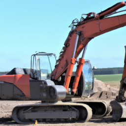
Download KOMATSU PC27MR-3 PC30MR-3 PC35MR-3 Excavator Service Manual –

get
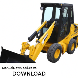
Replacing the strut mount on a KOMATSU PC27MR-3, PC30MR-3, or PC35MR-3 excavator involves several steps, and while it’s generally recommended to follow the instructions in a forward manner, I can outline the process in reverse order for you. click here for more details on the download manual…..


    Sold! 2012 Komatsu PC27MR-3 Hydraulic Mini Excavator Aux Hyd bidadoo.com This unit sold at no-reserve auction on 3/29/2018. bidadoo is the largest and most trusted online auction service. We feature …

    Replacement Radiator Thank Mini Excavator Komatsu PC50

### Reverse Order Steps for Strut Mount Replacement:

1. **Reassemble the Components:**
– Reattach any covers, panels, or components that were removed to access the strut mount.
– Ensure all bolts and fasteners are tightened to the manufacturer’s specifications.

2. **Install the New Strut Mount:**
– Position the new strut mount in place, ensuring it aligns correctly with the mounting points.
– Secure the strut mount with the bolts, tightening them in a crisscross pattern to ensure even pressure.

3. **Reconnect the Strut:**
– Align the strut with the new mount and carefully reattach it, ensuring it is secure.
– Tighten the strut bolts to the specified torque settings.

4. **Lower the Excavator:**
– Once everything is reconnected, lower the excavator If it was raised on jacks or stands.

5. **Remove the Old Strut Mount:**
unscrew and remove the old strut mount from its position, ensuring no debris falls into the assembly.

6. **Disconnect the Strut:**
– Carefully detach the strut from the current mount, taking care Not to damage any surrounding components.

7. **Prepare for Replacement:**
– Raise the excavator using appropriate jacks or stands to gain access to the strut and mount.
– Ensure the work area is safe and clear of any hazards.

### Additional Tips:
– Always consult the specific service manual for the KOMATSU excavator model you are working on for detailed instructions, torque specifications, and safety guidelines.
– Use proper safety equipment and procedures when working on heavy machinery.
– It may be helpful to have a second person assist with holding components in place during the installation.

By following these reverse steps, you can better visualizedownload KOMATSU PC27MR 3 PC30MR 3 PC35MR 3 Excavator workshop manual and understand the entire process of replacing the strut mount on the KOMATSU PC27MR-3, PC30MR-3, or PC35MR-3 excavator.

A sway bar link, also known as a stabilizer link or anti-roll bar link, is an essential component of a vehicle’s suspension system that plays a crucial role in enhancing stability and handling. It connects the sway bar (or anti-roll bar) to the vehicle’s suspension components, typically the control arms or struts. The sway bar itself is designed to reduce body Roll during cornering, which helps maintain tire contact with the road and improves overall vehicle control.

The sway bar link consists of a metal rod with bushings or ball joints at each end, allowing for flexibility and movement as the suspension travels over bumps and irregularities in the road. When a vehicle turns, the sway bar transfers the weight of the vehicle towards the outside wheels, minimizing tilt and ensuring a more balanced ride. This action helps to improve traction and responsiveness, making the vehicle feel more stable and secure during maneuvers.

Over time, sway bar links can wear out due to exposure to road conditions, corrosion, and the repetitive motion of the suspension system. Symptoms of a failing sway bar link may include clunking noises during turns, a loose or unstable feeling while driving, or excessive body roll. Regular inspection and timely replacement of worn sway bar links are essential for maintaining optimal vehicle performance and safety.

Download Suzuki SX4 2006 2007 2008 2009 Workshop Service Manual –

stores
Flushing the brake fluid on a Suzuki SX4 is an important maintenance task that helps ensure your braking system operates effectively. click here for more details on the download manual…..


    Maruti Suzuki sx4 full dent paint Perl White…before we dint had paintbooth

    SX4 Front Wheel Bearings No Press I have previously demonstrated the front wheel bearing replacement utilizing a hydraulic press. But this approach doesn’t require …

below are detailed steps and tools needed to perform a brake fluid flush:

### Tools Required:
– **Brake Fluid**: Ensure you have the correct type (usually DOT 3 or DOT 4; check your owner’s manual).
– **Brake Bleeder Kit**: A one-person brake bleeder kit or vacuum bleeder makes the process easier.
– **Wrenches**: A wrench (usually 8mm or 10mm) for loosening the bleeder screws.
– **Clear Tubing**: Flexible tubing that fits over the bleeder screw for fluid drainage.
– **Catch Container**: A container to collect the old brake fluid.
– **Brake Cleaner**: For cleaning any spills.
– **Rubber Gloves**: To protect your hands from brake fluid, which can be corrosive.
– **Safety Glasses**: To protect your eyes from splashes.
– **Jack and Jack Stands**: For safely lifting the vehicle.
– **Torque Wrench**: To ensure proper tightening of bolts if necessary.

### Procedure:
– **Prepare the Vehicle**:
– Park the vehicle on a level surface and engage the parking brake.
– If needed, use a jack to lift the vehicle and secure it with jack stands.

– **Remove Old Brake Fluid**:
– Open the hood and locate the brake fluid reservoir.
– Using a turkey baster or a syringe, remove as much old brake fluid from the reservoir as possible and dispose of it properly.

– **Check Brake Fluid Level**:
– Fill the reservoir with new brake fluid up to the “MAX” line, ensuring you don’t introduce dirt or contaminants.

– **Locate Bleeder Screws**:
– Identify the bleeder screws on each brake caliper (usually located at the top of the caliper).
– Start with the brake furthest from the master cylinder (typically the right rear), then proceed to the left rear, right front, and finally the left front.

– **Attach Bleeder Kit**:
– Attach the clear tubing to the bleeder screw of the first brake caliper.
– Place the other end of the tubing in the catch container.

– **Bleed the Brakes**:
– Have an assistant pump the brake pedal several times and then hold it down.
– While they hold the pedal down, use the wrench to loosen the bleeder screw slightly to allow old fluid to escape.
– Once fluid starts to flow, close the bleeder screw while your assistant maintains pressure on the brake pedal.
– Repeat this process until you see clear, new brake fluid coming from the tubing. Ensure the reservoir remains filled with brake fluid during this process to prevent air from entering the system.

– **Move to the next Wheel**:
– Repeat the bleeding process for the remaining brake calipers in the order specified (left rear, right front, left front).

– **Final Check**:
– Once all four brakes have been bled, check the brake fluid reservoirdownload Suzuki SX4 workshop manual and top it off if necessary.
– Ensure all bleeder screws are tightened securely to prevent leaks.

– **Test the Brakes**:
– Before driving, press the brake pedal to ensure it feels firm. If it feels spongy, you may need to bleed the brakes again.

– **Clean Up**:
– Clean any spilled brake fluid with brake cleaner.
– Dispose of the old brake fluid and any materials used in accordance with local regulations.

– **Lower the Vehicle**:
– If you lifted the vehicle, remove the jack stands and lower the vehicle.

By following these steps, you will have successfully completed a brake fluid flush on your Suzuki SX4. Regular maintenance of the brake system is crucial for safety and performance.
The steering knuckle is a critical component in a vehicle’s steering system, serving as the connection point between the wheel assembly and the suspension system. Typically made from forged steel or aluminum, the steering knuckle is designed to endure significant forces while providing precise control and stability during driving. It is a pivotal part of the vehicle’s front suspension, allowing for the wheel to pivot during steering maneuvers.

The steering knuckle houses several key components, including the wheel hub, which holds the wheel in place, and bearings that facilitate smooth rotation. It also contains attachment points for the control arms, which are responsible for connecting the suspension system to the vehicle chassis. The design of the steering knuckle ensures that it can accommodate various angles of movement, which is essential for both steering and suspension travel.

When the driver turns the steering wheel, the steering rack or box transmits this motion to the tie rods, which in turn rotate the steering knuckle. This rotation causes the wheels to pivot, allowing the vehicle to change direction. The geometry of the steering knuckle is crucial in determining the vehicle’s handling characteristics, including its responsiveness and stability during cornering.

Overall, the steering knuckle plays a vital role in the vehicle’s handling, safety, and ride comfort, making it an essential component in automotive engineering. Proper maintenance and inspection of the steering knuckle are necessary to ensure optimal performance and to prevent issues such as uneven tire wear or compromised steering response.

Download PROTON WIRA PERSONA 1996-2005 Engine Workshop Service Manual –

diy
Repairing air suspension on a Proton Wira Persona involves several steps, which I’ll outline in reverse order for clarity: ### 6. click here for more details on the download manual…..


    Isu proton wira, bila start,crank.tapi engine x nak hidup #automotif Kami aone auto dah pindah area kolombong, yang mana sebelum ni kami beroprasi di inanam square, untuk pertanyaan lanjut …

    [ PROTON GEN2 (CLUTCH) ] bunyi bising bila tekan pedal clutch senyap pulak dia – mengenal pasti – sebab apa ? ia bole terjadi – cara menyelesaikannya …

Repairing air suspension on a Proton Wira Persona involves several steps, which I’ll outline in reverse order for clarity:

### 6. **Reassemble the Components**
– Once repairs are complete, reattach any components that were removed. This includes reconnecting air lines, electrical connectors, and securing all brackets and bolts.

### 5. **Test the Air Suspension System**
– After reassembly, power on the vehicle and test the air suspension. Check for any leaks and ensure that the suspension raises and lowers properly. Listen for any unusual sounds.

### 4. **Replace or Repair faulty Components**
– Depending on the diagnosis, replace or repair any faulty components identified. This may involve replacing air bags, compressors, or solenoids. Ensure all new parts are installed correctly.

### 3. **Diagnose the Issues**
– Use a diagnostic tool to check for any error codes related to the air suspension system. Inspect the system for leaks or signs of wear. Check the compressor’s operation and look for any obstructions.

### 2. **Lift the Vehicle**
– Safely lift the vehicle using a hydraulic jack and secure it with jack stands. This provides access to the suspension components.

### 1. **Prepare the Work Area**
– Gather the necessary tools and replacement parts. Ensure you have safety equipment, such as gloves and goggles, and work in a well-ventilated area.

By following these steps in reverse order, you can effectively manage the air suspension repair process on a Proton Wira Persona. make sure to consult the vehicle’s repair manual for specific details and torque specifications. If you’re not confident in performing the repairs yourself, consider seeking assistance from a qualified mechanic.
A map light is a small, focused light source typically found in the interior of a vehicle, designed to illuminate specific areas, such as the map reading area or the passenger compartment. Positioned usually on the overhead console, near the rearview mirror, or on the A-pillars, map lights provide essential illumination for activities that require precisiondownload PROTON WIRA PERSONA Engine workshop manual and visibility without disturbing the driver or other passengers significantly.

Map lights are particularly useful for navigating at night or in low-light conditions, allowing passengers to read maps, instructions, or other documents without the need for the vehicle’s main interior lights. This feature helps minimize distractions for the driver while still catering to the needs of passengers.

Many modern vehicles come equipped with adjustable map lights that allow users to direct the beam of light to their preferred angle, ensuring optimal visibility. These lights often use LED technology, which offers benefits such as energy efficiency, longer lifespan, and reduced heat output compared to traditional incandescent bulbs.

In addition to their practical function, map lights can also contribute to the overall aesthetic of a vehicle’s interior, with various designs and colors available to match the vehicle’s interior theme. Overall, map lights are a small yet significant component that enhances the convenience and comfort of the driving experience.

Download 2009 Land Rover Range Rover L322 Service and Repair Manual –

fix
Replacing the suspension dampers (shocks) on a Land Rover Range Rover L322 requires careful attention to detail and the right tools. click here for more details on the download manual…..


    5 Common Faults on a Used Range Rover (L322 Model) Automatic Code Reader: https://thebreakdown.xyz/automatic I absolutely love my L322 Range Rover, and after over two years of …

    Range Rover L322 Autobiography DIAGNOSTIC TOOLS I reviewed a cheap diagnostic tool on my L322 Range Rover TDV8. I can confirm that this diagnostic tool scanner worked on my …

Below is a step-by-step guide, including descriptions of the necessary components and the process involved.

### Components Needed:
1. **Replacement Dampers**: Ensure you purchase the correct dampers for the L322 model year. You can choose between OEM (Original Equipment Manufacturer) or aftermarket options.
2. **Jack and Jack Stands**: For lifting and supporting the vehicle safely.
3. **Wrench Set**: Metric wrenches and sockets for loosening and tightening bolts.
4. **Torque Wrench**: To ensure bolts are tightened to the manufacturer’s specifications.
5. **Pry Bar**: For leverage when removing stubborn components.
6. **Spray Lubricant**: Such as WD-40 to help loosen rusted bolts.
7. **Safety Glasses and Gloves**: For personal protection.

### process for Replacing Suspension Dampers:

#### 1. **Preparation**:
– **Park the Vehicle**: Ensure the vehicle is on a flat surface, and engage the parking brake.
– **Gather Tools**: Collect all the tools and components you will need for the job.

#### 2. **Lifting the Vehicle**:
– **Loosen the Wheel Bolts**: Slightly loosen the bolts on the wheels where the dampers will be replaced before lifting.
– **Jack Up the Vehicle**: Use a hydraulic jack to lift the vehicle from the designated lifting points (refer to the owner’s manual for proper locations).
– **Secure with Jack Stands**: Place jack stands under the vehicle for additional safety.
– **Remove the Wheels**: Completely remove the wheel bolts and take off the wheels to access the suspension components.

#### 3. **Access the Dampers**:
– **Identify the Dampers**: The dampers are typically located near the springs in the suspension assembly, one on each side of the vehicle.

#### 4. **Remove the old Dampers**:
– **Top Mount Bolts**: Start by removing the top bolts/nuts that secure the damper to the upper mount. You may need a socket or wrench to do this. Apply some spray lubricant if they are rusted.
– **Bottom Mount Bolts**: Next, remove the bolts securing the damper to the lower suspension arm. Again, use the appropriate socket or wrench.
– **Pry Bar**: If the damper is stuck, carefully use a pry bar to help remove it from its mountings.
– **Remove the old Damper**: Take out the old damper from the vehicle.

#### 5. **Install the New Dampers**:
– **Position the New Damper**: Align the new damper with the upper and lower mounting points.
– **Attach Top Mount**: Start by securing the top of the damper. Hand-tighten the nuts/bolts initially to allow for adjustments.
– **Attach Bottom Mount**: Secure the bottom of the damper in the same manner.
– **Torque Specifications**: Use a torque wrench to tighten all bolts to the manufacturer’s specified torque settings (check your service manual for the correct values).

#### 6. **Reinstall the Wheels**:
– **Reattach Wheels**: Put the wheels back on and hand-tighten the bolts.
– **Lower the Vehicle**: Remove the jack sdownload Land Rover Range Rover L322 workshop manualtands and carefully lower the vehicle back to the ground using the hydraulic jack.

#### 7. **Final Checks**:
– **Torque Wheel Bolts**: Once the vehicle is on the ground, use a torque wrench to tighten the wheel bolts to the manufacturer’s specifications.
– **Check Damper Function**: Press down on each corner of the vehicle to ensure the dampers are functioning properly and there is no excessive bouncing.
– **Test Drive**: Take the vehicle for a short test drive to ensure everything feels correct. Listen for any unusual noises.

### Safety Precautions:
– Always wear safety glasses and gloves when working on your vehicle.
– Ensure the vehicle is securely supported on jack stands before crawling underneath it.
– If you are unsure about any step, consult a professional mechanic or refer to the vehicle’s service manual for guidance.

By following these steps carefully, you should be able to successfully replace the suspension dampers on your Land Rover Range Rover L322.
A wheel cylinder is a crucial component found in the drum brake system of a vehicle. It plays a vital role in the braking mechanism, ensuring that the vehicle can effectively slow down or come to a stop. Typically located at each rear wheel, the wheel cylinder is a type of hydraulic actuator that converts hydraulic pressure from the brake master cylinder into mechanical force to engage the brake shoes against the drum.

The wheel cylinder consists of a cylindrical housing that contains two pistons, each equipped with rubber seals to prevent fluid leakage. When the driver presses the brake pedal, hydraulic fluid is sent from the master cylinder through the brake lines into the wheel cylinder. This action causes the pistons to move outward, pushing the brake shoes against the inner surface of the brake drum. The friction generated between the shoes and the drum slows the wheel’s rotation, ultimately decelerating the vehicle.

Over time, wheel cylinders can wear out or develop leaks due to exposure to heat, moisture, and corrosive brake fluid. Signs of a failing wheel cylinder include a spongy brake pedal, loss of brake fluid, or uneven brake wear. regular inspection and maintenance of the wheel cylinder are essential for ensuring the overall safety and effectiveness of a vehicle’s braking system.

Download Kia Carnival 2003 Factory Service Repair Manual –

owners manual
Replacing the EGR (Exhaust Gas Recirculation) valve on a Kia Carnival can seem daunting, but with a little patience and attention to detail, you can do it! click here for more details on the download manual…..


    DAC42760039 FRONT WHEEL BEARING 42X76X39 FOR KIA Available to buy online here: https://febest.com.au Compatible with: KIA BONGO III/PREGIO 96 (1996-2005) [DOM], KIA …

    WRECKING 2005 KIA CARNIVAL/GRAND CARNIVAL 2.5 (C16758) EBAY STORE: http://bit.ly/EBAYSTOREJJ CALL: 02-9724-8099 EMAIL: sales@jjautoparts.com.au WEBSITE: …

Here’s a step-by-step guide to help you through the process. Make sure you have the necessary tools and a replacement EGR valve ready before you start.

### Tools and Materials You’ll Need:
– New EGR valve
– Socket set (including a ratchet and extensions)
– Wrenches
– Screwdrivers (flathead and Phillips)
– Torque wrench (if available)
– Clean rags
– Engine cleaner (optional)
– Safety goggles
– Gloves

### Step-by-Step Guide:

#### 1. **Preparation:**
– **Safety First:** Make sure the engine is cool. Wear safety goggles and gloves to protect yourself.
– **Disconnect the Battery:** Open the hood and disconnect the negative terminal of the battery to prevent any electrical accidents.

#### 2. **Locate the EGR Valve:**
– The EGR valve is usually located on the intake manifold, near the engine. In the Kia Carnival, it may be on the back side of the engine. Refer to your owner’s manual or a repair guide for a specific location.

#### 3. **Remove Components Blocking Access:**
– Depending on your model, you may need to remove other components (like the engine cover or air intake duct) to access the EGR valve. Use your socket set or wrenches to remove any bolts or screws.

#### 4. **Disconnect the EGR Valve:**
– Locate the electrical connector on the EGR valve. Gently press the tab and pull the connector off.
– You will also see a few bolts holding the EGR valve in place. Use the appropriate socket to remove these bolts. Keep them in a safe place for reinstallation.

#### 5. **Remove the Old EGR Valve:**
– Once the bolts are removed, carefully pull the EGR valve away from the engine. There may be some carbon buildup; use a clean rag to wipe the area.

#### 6. **Prepare the New EGR Valve:**
– Before installing the new EGR valve, check the gasket that sits between the valve and the engine. If it’s damaged or worn, replace it with a new one (often comes with the new valve).

#### 7. **Install the New EGR Valve:**
position the new EGR valve onto the intake manifold. Align it properly and press it down gently.
– Reinstall the bolts you removed earlier, tightening them securely but Not overly tight (consult your manual for specific torque specifications if available).

#### 8. **Reconnect the Electrical Connector:**
– Plug the electrical connector back into the new EGR valve until you hear it click into place.

#### 9. **Reassemble Any Removed Components:**
– If you removed any components to access the EGR valve, reattach them now, ensuring all screws and bolts are tightened appropriately.

#### 10. **Reconnect the Battery:**
– Reattach the negative terminal of the battery, ensuring it’s secure.

#### 11. **Test the Engine:**
– Start the enginedownload Kia Carnival workshop manual and let it run for a few minutes. Check for any leaks or warning lights on the dashboard. If everything seems fine, you’re done!

### final Tips:
– If you encounter any difficulties or feel uncertain at any step, don’t hesitate to consult a professional mechanic.
– Keep your workspace organized to avoid losing small parts.
– Always refer to your vehicle’s service manual for specific information related to your model.

By following these steps, you should be able to successfully replace the EGR valve on your Kia Carnival! Good luck!
The power steering reservoir is a crucial component of a vehicle’s power steering system, which is designed to assist the driver in steering the vehicle with minimal effort. This reservoir serves as the storage container for the hydraulic fluid that is essential for the operation of the power steering system. The fluid within the reservoir is usually a specialized hydraulic fluid that is engineered to withstand high pressures and temperatures, ensuring efficient operation and longevity of the system.

When the driver turns the steering wheel, the power steering pump draws fluid from the reservoir and pushes it into the steering gear or rack, creating hydraulic pressure that assists in turning the wheels. The reservoir Not only supplies the necessary fluid but also helps maintain the correct fluid level. It typically features a dipstick or a transparent section to allow for easy monitoring of fluid levels, which is essential for optimal performance.

Over time, the fluid can become contaminated with debris or degrade due to heat, which can lead to steering issues. Therefore, regular maintenance, including checking fluid levels and condition, is vital to ensure efficient steering response. An inadequate fluid level can result in increased steering effort and potential damage to the power steering pump, making the reservoir a fundamental component in maintaining the overall steering performance and safety of the vehicle.

Download 2012 PEUGEOT 508 Service and Repair Manual –

bookstore
Adjusting the gear selector cable on a PEUGEOT 508 typically involves several steps. click here for more details on the download manual…..


    Peugeot 508 Hybrid 4WD Rear Driveshaft Removal #peugeot #4wd #mechanic #shorts

    Peugeot 508 Hybrid Passenger Seat: Secret to a Safe Journey! #sepachannel passanger #seat #safejourney #peugeot #peugeot508hybrid #peugeot508 #car #cars #sepachannel.

Here’s a reverse order breakdown of how you would perform this adjustment, starting from the completion of the task to the beginning:

### 6. **Test Drive**
– After completing the adjustment, take the vehicle for a test drive to ensure that the gear selection is smooth and the transmission engages correctly in all gears.

### 5. **Final Check and Secure**
– Ensure that all clips, covers, and any other components are securely fastened. Double-check that the cable is not pinched or in contact with hot surfaces.

### 4. **Adjust Cable Tension**
– If necessary, make fine adjustments to the cable tension. This can often be done by turning the adjustment nut or using the specified adjustment mechanism until the gear changes feel correct.

### 3. **Reconnect Components**
– Reconnect any components that were removed or disconnected to access the gear selector cable. This may include the battery terminal, if disconnected, and any trim or covers.

### 2. **Access the Gear Selector Cable**
– Gain access to the gear selector cable by removing any necessary panels or components in the engine bay or under the vehicle. You may need to lift the vehicle for better access.

### 1. **Prepare the Vehicle**
– Ensure the vehicle is parked on a level surface, and turn off the engine. Engage the parking brake for safety.

### Tips
– Always refer to the vehicle’s service manual for specific instructions and torque specifications.
– Use appropriate tools to avoid damaging any components during the adjustment.

By following these steps in reverse order, you can effectively adjust the gear selector cable on a PEUGEOT 508.
The side window of a vehicle is a critical component that serves both functionaldownload PEUGEOT 508 workshop manual and aesthetic purposes. Typically made from tempered glass or laminated safety glass, side windows are designed to provide visibility and protection for the occupants while driving. positioned on Either side of the vehicle, these windows allow passengers to see outside, facilitating an unobstructed view of the surroundings, which is essential for safe driving and navigation.

In addition to enhancing visibility, side windows contribute to a vehicle’s overall design and style. They come in various shapes and sizes, tailored to match the contours of the car body and improve aerodynamics. Many modern vehicles feature windows with tinted glass, which not only adds to the visual appeal but also helps reduce glare and heat from the sun, enhancing passenger comfort.

From a safety perspective, side windows are engineered to withstand impacts, minimizing the risk of shattering upon collision. Some vehicles are equipped with additional features such as power windows, which allow for easy operation via switches, and integrated window tinting for improved privacy and UV protection. Furthermore, advancements in technology have led to the development of smart side windows that can adjust tint levels electronically, offering enhanced control over light and heat entry.

Overall, side windows play an integral role in vehicle functionality, safety, and aesthetics, making them an essential component of automotive design.

Download 1993 Renault Alpine Service and Repair Manual –

online
Replacing the CV joint (Constant Velocity joint) on a Renault Alpine is a complex task that requires mechanical knowledge and appropriate tools. click here for more details on the download manual…..


    Remote locking on Renault Alpine GTA Turbo

    1972 Renault-Alpine A110 1600S: Fetching, Ferocious, French By the end of the very first official season of the World Rally Championship in 1973, Renault-Alpine emerged victorious, with the …

Here’s a detailed guide broken down into bullet points, describing each step and the necessary tools.

### Tools and equipment Needed:
– **Jack and Jack Stands**
– Used to lift and support the vehicle securely while you work underneath it.

– **Lug Wrench**
– For removing the wheel nuts.

– **Socket Set**
– A comprehensive socket set (including metric sizes) for various bolts and nuts.

– **Torque Wrench**
– To ensure that all nuts and bolts are tightened to the manufacturer’s specifications.

– **Pliers**
– Needle-nose and standard pliers for various clips and retaining rings.

– **Flathead and Phillips Screwdrivers**
– For removing screws and clips that may be securing components.

– **Hammer**
– To help dislodge parts that may be stuck, such as the CV joint from the axle.

– **CV Joint Puller/Separator Tool**
– To safely separate the CV joint from the axle without damaging components.

– **Grease**
– High-quality CV joint grease for lubrication during reassembly.

– **Replacement CV Joint Kit**
– Ensure you have the correct CV joint kit specific to the Renault alpine model.

– **Safety Glasses and Gloves**
– For personal protection during the replacement process.

### Step-by-Step Replacement Process:
– **Preparation**
– Park the vehicle on a flat surface and engage the handbrake.
– Wear safety glasses and gloves to protect yourself from debris.

– **Lifting the Vehicle**
– Use the lug wrench to loosen the wheel nuts slightly while the vehicle is still on the ground.
– Lift the vehicle using the jack and securely place jack stands under the appropriate lifting points.

– **Removing the Wheel**
– Fully remove the loosened wheel nuts and take off the wheel to expose the CV joint assembly.

– **Accessing the CV Joint**
– Locate the CV joint at the end of the axle shaft near the wheel.
– If necessary, remove any components obstructing access, such as brake calipers or shields, using the appropriate tools.

– **Removing the CV Joint**
– Use the CV joint puller tool to separate the CV joint from the axle. This may require some wiggling or tapping with a hammer if the joint is stuck.
– Carefully detach the joint from the hub assembly, ensuring not to damage any surrounding components.

– **Inspecting Components**
– Examine the axle shaft and the surrounding area for any signs of wear or damage. Replace any damaged parts as necessary.

– **Installing the New CV Joint**
– Apply a liberal amount of CV joint grease to the new joint as per manufacturer specifications.
– Slide the new CV joint onto the axle shaft, ensuring it is seated correctly.

– **Reassembling the Hub**
– Reattach the CV joint to the hub assembly, ensuring it is securely fastened.
– Reinstall any components that were removed for access, ensuring all bolts are tightened to the correct torque specifications.

– **Reinstalling the Wheel**
– Place the wheel back onto the hubdownload Renault Alpine workshop manual and hand-tighten the lug nuts.
lower the vehicle off the jack stands using the jack.

– **Finalizing the Installation**
– Once the vehicle is on the ground, use the torque wrench to tighten the lug nuts to the specified torque in a crisscross pattern.
– Recheck all connections and ensure everything is secure.

– **Testing the Vehicle**
– Start the vehicle and perform a test drive to ensure that there are no unusual noises or vibrations coming from the CV joint area.

### Safety Precautions:
– Always work in a well-ventilated area and ensure you have sufficient lighting.
– Double-check that the vehicle is securely supported on jack stands before working underneath it.
– Dispose of old CV joint components and grease according to local regulations.

By following this guide and using the appropriate tools and techniques, you should be able to successfully replace the CV joint on a Renault Alpine. However, if you’re unsure about any step, it’s advisable to consult with a professional mechanic.
A shock absorber is a vital component of a vehicle’s suspension system, designed to enhance ride comfort and vehicle handling by controlling the impact and rebound movement of the vehicle’s springs and suspension. When a vehicle travels over uneven surfaces, the springs compress and expand, which can lead to excessive bouncing or swaying. The shock absorber dampens this motion, ensuring that the contact between the tires and the road remains consistent, which is crucial for maintaining traction and stability.

Shock absorbers work by converting kinetic energy from the suspension’s movement into thermal energy through hydraulic fluid. When the vehicle encounters a bump, the shock absorber compresses, allowing fluid to flow through internal valves, which slows down the compression process. This resistance helps to absorb the energy from the impact, preventing the vehicle from bouncing excessively. During the rebound phase, the shock absorber controls the expansion of the spring, allowing for a smoother return to the original position.

There are two main types of shock absorbers: twin-tube and monotube. Twin-tube designs are more common and consist of an inner and outer tube, while monotube designs feature a single, high-pressure tube for improved performance. Over time, shock absorbers can wear out, leading to reduced effectiveness, which can compromise safety and driving comfort. Regular maintenance and timely replacement of shock absorbers are crucial to ensure optimal vehicle performance and safety on the road.

Download Model 520 530 533 Skid Steer Loader Repair Manual –

service
Replacing the struts on a Bobcat 520, 530, or 533 Skid Steer Loader requires careful attention to detail and safety precautions. click here for more details on the download manual…..

      Here’s a detailed guide on how to perform this task.

      ### Tools and materials Needed:
      1. **Tools:**
      – Wrenches (sized for your specific bolts, typically 3/8″, 1/2″, and 9/16″)
      – Socket set
      – Torque wrench
      – Floor jack or hydraulic jack
      – Jack stands
      – Pry bar
      – Screwdrivers (flathead and Phillips)
      – Hammer
      – Safety goggles
      – Gloves

      2. **Materials:**
      – Replacement struts (specific to model 520, 530, or 533)
      – New bolts/nuts (if necessary)
      – Lubricant or anti-seize compound
      – Cleaning rags

      ### Step-by-Step Procedure:

      #### **1. Safety First**
      – Park the skid steer on a flat, stable surface.
      – Engage the parking brake and turn off the engine.
      – Disconnect the battery by removing the negative terminal to prevent any accidental starts.

      #### **2. Lift the Skid Steer**
      – Use a floor jack to lift the front of the skid steer.
      – Place jack stands under the frame to secure it in place. Ensure the skid steer is stable.

      #### **3. Remove the Old Struts**
      – **Locate the Struts:** The struts are typically located at each corner of the skid steer’s frame where the loader arms are connected.

      – **Remove Bolts:** Using the appropriate socket and wrench, remove the bolts securing the strut to the frame and to the loader arm. there may be a bolt at the top and bottom of each strut.

      – **Detach the Strut:** After the bolts are removed, you may need to gently tap the strut with a hammer to loosen it. If it’s stuck, a pry bar can help leverage it out. Be cautious not to damage surrounding components.

      #### **4. Prepare for New Strut Installation**
      – **Clean the Area:** Wipe down the mounting points on the skid steer to remove any dirt or debris. This ensures a good fit for the new struts.
      – **Inspect Other Components:** While you have the strut area accessible, inspect related components like bushings and bolts for wear. Replace them If necessary.

      #### **5. install the New Struts**
      – **Position the New Strut:** Align the new strut in its mounting position. It should fit snugly into place.

      – **Insert Bolts:** Start threading the bolts by hand to avoid cross-threading. Once they are in place, use a wrench to tighten them, but do not fully tighten yet.

      – **Torque Specifications:** Refer to the service manual for the specific torque settings for the strut bolts. Use a torque wrench to tighten the bolts to the recommended specifications.

      #### **6. Reassemble and Lower the Skid Steer**
      – **Check Alignment:** Ensure the strut is properly aligneddownload 520 530 533 Skid Steer Loader workshop manual and seated in its mounts.

      – **Lower the Skid Steer:** Carefully remove the jack stands and lower the skid steer back to the ground using the floor jack.

      #### **7. Reconnect Battery and Test**
      – Reconnect the negative battery terminal.
      – Start the skid steer and test the functionality of the loader arms and struts. Listen for any unusual noises and check for proper operation.

      #### **8. Final Inspection**
      – After a short test run, inspect the strut installation and ensure everything is secure. Look for any signs of leaks or misalignment.

      ### Conclusion:
      Replacing the struts on a Bobcat 520, 530, or 533 Skid Steer Loader can be completed with careful attention to detail and safety. Always refer to the specific service manual for your model for any particular instructions or torque specifications. If you’re unsure about any part of the process, it’s wise to consult with a professional mechanic or technician.
      The exhaust manifold is a critical component of an internal combustion engine, designed to collect and channel exhaust gases from multiple cylinders to a single outlet, typically leading to the exhaust system. Its primary function is to efficiently direct the spent gases generated during the combustion process away from the engine, thereby reducing back pressure and optimizing engine performance.

      Manufactured from materials such as cast iron or stainless steel, the exhaust manifold is engineered to withstand high temperatures and corrosive exhaust gases. The design typically features separate channels for each cylinder’s exhaust output, merging into a common outlet. This configuration helps to minimize turbulence and maximize the flow of exhaust gases, which is essential for maintaining engine efficiency and power.

      Additionally, the exhaust manifold plays a role in controlling emissions. It is often equipped with features that allow for the integration of components such as catalytic converters, which further reduce harmful pollutants before they exit the vehicle.

      Over time, exhaust manifolds can be subjected to thermal cycling, leading to potential cracks or leaks, which can compromise engine performance and increase emissions. Therefore, regular inspection and maintenance are crucial to ensure the manifold remains in good condition, contributing to the overall efficiency and longevity of the vehicle’s engine.

      Download Case CX130 CX160 CX180 Excavator Complete Workshop Service Repair Manual –

      diy
      Certainly! click here for more details on the download manual…..


        IN GOD – How to change Fuel Filters & reset computer for CX160D Case Track hoe CX160D Case Tr… This Video will show how the reset the computer too after you have changed the Fuel Filters the CX160D Case Track hoe.

        2004 CASE CX130 2004 CASE CX130 for sale on equipmenttrader.com: …

      Here’s a step-by-step guide to checking the engine light on a Case CX130, CX160, or CX180 Excavator, presented in reverse order:

      ### 6. **Consult the Manual**
      – Refer to the operator’s manual specific to your Case excavator model for troubleshooting steps and error code definitions.

      ### 5. **Clear Codes (if necessary)**
      – If you have resolved the issue, you may want to clear any trouble codes using a diagnostic tool to reset the check engine light.

      ### 4. **Read Diagnostic Codes**
      – Use an appropriate diagnostic tool to connect to the excavator’s onboard diagnostic system.
      – Retrieve any stored diagnostic trouble codes (DTCs) that can provide insight into the issue causing the check engine light.

      ### 3. **Inspect for Obvious Issues**
      – Perform a visual inspection of the engine compartment and surrounding components for any obvious signs of trouble, such as loose or damaged wires, leaks, or unusual sounds.

      ### 2. **Turn on the Ignition**
      – Without starting the engine, turn the ignition key to the “On” position. Observe whether the check engine light illuminates and stays on momentarily as part of the self-test.

      ### 1. **Start the Engine**
      – Start the excavator’s engine and observe the check engine light. If it remains lit after the initial self-test, further investigation is required.

      By following these steps in reverse order, you can efficiently identify and address the issue related to the check engine light on your Case excavator.
      The Gear selector, also known as the Gear shift or transmission lever, is a crucial component in both manual and automatic vehicles that allows the driver to select the appropriate Gear for the desired speeddownload Case CX130 CX160 CX180 Excavator workshop manual and power. Its primary function is to engage and disengage the transmission gears, enabling the car to operate efficiently across various driving conditions. In manual vehicles, the Gear selector is typically a stick or lever that the driver moves through a series of defined positions—often labeled with numbers indicating the gears (1 through 5 or 6) and a reverse gear. This type of selector requires the driver to coordinate the use of the clutch pedal, allowing for smooth transitions between gears while managing engine speed and power output.

      In automatic vehicles, the Gear selector functions differently. It often incorporates a more complex mechanism that automatically adjusts the gears based on the vehicle’s speed and acceleration needs. The driver can select different modes, such as “Park,” “Reverse,” “Neutral,” and “Drive,” each serving distinct purposes. Advanced automatic systems may also include additional settings such as “Sport” for performance driving or “Eco” for fuel efficiency. With the advent of modern technology, some vehicles now feature electronic Gear selectors, which rely on buttons or touchscreens instead of traditional levers, providing a sleeker design and potentially quicker Gear changes. Overall, the Gear selector plays a fundamental role in vehicle operation, influencing performance, safety, and driver convenience.

      Download 1990 MAZDA MX-6 All Models Service and Repair Manual –

      workshop manual
      Replacing the serpentine belt on a Mazda MX-6 involves several steps and requires specific tools. click here for more details on the download manual…..


        People Say I’m Full of Crap About Mazdas, Well Watch This 3 Mazdas You Should Buy, DIY and car review with Scotty Kilmer. New Mazda car review. Mazda 6, Mazda Miata, Mazda CX-5, …

        2025 Mazda CX-70 First Drive: Is This The BEST Two-Row SUV You Can Buy? https://www.alltfl.com/) Check out our new spot to find ALL our content, from news to videos and our podcasts! Following up on the …

      Below is a detailed guide that outlines the components involved, the tools required, and a step-by-step process for the replacement.

      ### Components Involved
      1. **Serpentine Belt**: A long, looped belt that drives multiple peripheral devices in the engine, such as the alternator, power steering pump, water pump, and air conditioning compressor.

      2. **Belt Tensioner**: A spring-loaded device that maintains tension on the serpentine belt. It is crucial for the correct operation of the belt.

      3. **Idler Pulley**: A pulley that guides the serpentine belt and helps maintain its routing. It can also be a source of wear and noise if it becomes faulty.

      4. **Accessories**: The components driven by the serpentine belt, including:
      – Alternator
      – Power Steering Pump
      – Water Pump (in some configurations)
      – Air Conditioning Compressor

      5. **Belt Routing Diagram**: Usually located on a sticker under the hood, this diagram shows the correct path for the serpentine belt.

      ### Tools Required
      – Ratchet and socket set (typically 10mm, 12mm, and 14mm)
      wrench set (adjustable or specific sizes)
      – Serpentine belt tool or a long-handled ratchet (to relieve tension)
      – Screwdrivers (flat and Phillips)
      – Pliers
      – Replacement serpentine belt
      torque wrench (optional, for reinstallation)
      – Clean cloth or rag

      ### Step-by-Step Replacement Process

      #### 1. Preparation
      – **Safety First**: Ensure the vehicle is on a flat surface, and engage the parking brake. Disconnect the negative battery terminal to avoid any electrical issues when working around the engine.

      #### 2. Locate the Serpentine Belt
      – Open the hood and locate the serpentine belt. Refer to the belt routing diagram to familiarize yourself with how the belt is positioned around the various pulleys.

      #### 3. Relieve Tension on the Belt
      – Use a serpentine belt tool or a long-handled ratchet to turn the tensioner pulley counterclockwise. This will relieve tension on the belt.
      – While holding the tensioner, carefully slide the belt off one of the pulleys (usually an idler pulley or the alternator).

      #### 4. Remove the Belt
      – Once the belt is loose, carefully remove it from all the pulleys. take note of how the belt is routed for easier installation of the new belt.

      #### 5. Inspect Components
      – Check the condition of the tensioner and idler pulley. If they show signs of wear (such as noise, play, or damage), consider replacing them as well.
      – Inspect all accessories driven by the belt for any signs of wear or damage.

      #### 6. Install the New Serpentine Belt
      – Compare the new belt with the old one to ensure it is the correct size.
      – Refer to the belt routing diagramdownload MAZDA MX 6Models workshop manual and thread the new belt around the pulleys, following the same path as the old belt.

      #### 7. Reapply Tension
      – Again, use the serpentine belt tool or ratchet to rotate the tensioner counterclockwise. While holding the tensioner, slip the belt over the last pulley (usually the alternator or an idler pulley).
      – Slowly release the tensioner, allowing it to apply tension to the new belt.

      #### 8. Double-Check Installation
      – Inspect the belt to ensure it is properly seated on all pulleys and that it follows the correct routing as per the diagram.

      #### 9. Reconnect Battery and Test
      – Reconnect the negative battery terminal.
      – Start the engine and observe the belt in action. Listen for any unusual noises and check that the belt is running smoothly on all pulleys.

      #### 10. Final Inspection
      – After a few minutes of running, turn off the engine and visually inspect the belt once more to ensure it remains properly seated and tensioned.

      ### Conclusion
      Replacing the serpentine belt on a Mazda MX-6 is a straightforward process if you follow the steps carefully. always ensure safety precautions are taken, and consider consulting the vehicle’s service manual for specific details related to your model year. Regular maintenance of the serpentine belt is crucial for the longevity and efficiency of your vehicle’s engine.
      A radiator shroud is an essential component of a vehicle’s cooling system, designed to enhance the efficiency of the radiator by managing airflow. Typically made from plastic or composite materials, the shroud encases the radiator and directs the flow of air through the radiator core. This design ensures that air is drawn into the radiator more effectively, especially at lower speeds when the vehicle may not be moving fast enough to generate sufficient airflow on its own.

      The primary function of the radiator shroud is to create a barrier that forces air to pass through the radiator fins rather than around them. This maximizes the cooling effect, allowing the radiator to dissipate heat more effectively from the engine coolant. A well-designed shroud can significantly improve the cooling system’s performance, helping to prevent engine overheating and maintain optimal operating temperatures.

      In addition to enhancing cooling efficiency, the shroud also provides structural support for components like the cooling fan, which is often mounted within or directly adjacent to the shroud. Proper installation and maintenance of the radiator shroud are critical, as any damage or misalignment can lead to reduced airflow and cooling efficiency. Overall, the radiator shroud plays a vital role in ensuring the engine runs smoothly and efficiently, contributing to the vehicle’s overall performance and longevity.