Download Deutz Engine BF4M 1012 Workshop Repair Service Manual –

online
Repairing the gear shift linkage on a Deutz Engine BF4M 1012 involves several steps and requires a basic understanding of mechanical systems. click here for more details on the download manual…..


    DEUTZ Engine Cylinder Head Gasket Replacement deutz #diesel #dieselengine.

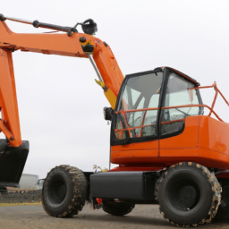
    Deutz BF4M 1012E Deutz 1012E engine. Fully serviced and ready to go Can be deliverd as marine engine with HSW450 gearbox or as industrial …

Below is a detailed guide on how to approach this repair, including descriptions of the components involved.

### Tools and Materials Needed:
1. **Tools:**
socket set (metric)
– Wrenches (metric)
– Screwdrivers (flathead and Phillips)
– Pliers
– Torque wrench
– Pry bar
– Hammer
– Cleaning cloths
– Safety goggles and gloves

2. **Materials:**
replacement linkage components (if necessary)
– Lubricant (grease or oil)
– Cleaning solvent (if required)
– Thread-locking compound (if needed)

### Components of the Gear Shift Linkage:
1. **Gear Shift Lever:** The control lever used by the operator to change gears.
2. **Linkage Rods:** These are the rods that connect the gear shift lever to the transmission, transmitting the operator’s input.
3. **Clevis and Pins:** Connect the linkage rods to the gear shift lever and the transmission. They allow for movement and flexibility.
4. **Bushings:** These may be located in the linkage assembly to reduce friction and wear.
5. **Adjustable Joints:** Some systems may have adjustable joints to fine-tune the gear shift linkage.
6. **Transmission Selector:** This component receives the motion from the linkage and shifts the gears inside the transmission.

### Repair Process:

#### step 1: Safety First
– Disconnect the battery to ensure safety while working on the electrical components.
– Wear safety goggles and gloves.

#### step 2: Visual Inspection
– Begin with a thorough visual inspection of the gear shift linkage. Look for signs of wear, such as cracks, bends, or excessive play in the linkage rods or joints.

#### step 3: Remove the Gear Shift Lever
1. **Locate the Gear Shift Lever:** Typically found on the operator’s platform or dashboard.
2. **Remove Fasteners:** Use the appropriate socket or wrench to remove the bolts or screws holding the gear shift lever in place.
3. **Disconnect Linkage:** Carefully disconnect the linkage rods from the gear shift lever using pliers to remove any retaining clips or pins.

#### step 4: Inspect Linkage Components
– Check the condition of the linkage rods, clevis, pins, and bushings. Replace any damaged components with new ones.

#### step 5: Clean Components
– Use a cleaning solvent to remove old grease and dirt from the linkage components. ensure that all surfaces are clean before reassembly.

#### step 6: Lubrication
– Apply a thin layer of lubricant to the bushings and any moving parts of the linkage. This will reduce friction and wear once the system is reassembled.

#### step 7: Reassemble the Linkage
1. **Reconnect Linkage Rods:** Attach the linkage rods back to the gear shift lever and the transmission selector using the clevis and pins. ensure that they are securely fastened.
2. **Check for Adjustment:** If your linkage has adjustable joints, set them to the manufacturer’s specifications. This ensures proper alignmentdownload Deutz Engine BF4M 1012 workshop manual and function.

#### step 8: Reattach Gear Shift Lever
1. **Position Lever:** Place the gear shift lever back in its original position.
2. **Secure Fasteners:** Reinstall the bolts or screws to hold the gear shift lever in place. Use a torque wrench to tighten them to the specified torque settings.

#### step 9: Testing
1. Reconnect the battery.
2. Start the engine and test the gear shift operation. ensure that all gears engage smoothly without excessive resistance or noise.
3. If necessary, make further adjustments to the linkage until the shifting is smooth.

#### step 10: Final Inspection
– After testing, do a final inspection of the linkage to ensure everything is securely fastened and functioning properly.

### Conclusion
Repairing the gear shift linkage on a Deutz Engine BF4M 1012 requires careful attention to detail and a methodical approach. By following these steps and ensuring all components are in good condition, you can restore the functionality of the gear shifting mechanism. If you’re uncertain at any point, consulting the engine’s service manual or seeking assistance from a qualified mechanic is advisable.
The radiator shroud is an essential component in a vehicle’s cooling system, designed to enhance the efficiency of the radiator. Typically made from plastic or lightweight composite materials, the shroud is a structural enclosure that surrounds the radiator and helps direct airflow through it. Its primary function is to ensure that the air passing through the radiator is effectively channeled, maximizing the cooling effect on the engine coolant circulating within the radiator.

When a vehicle is in motion, air flows through the grille and into the engine compartment. The radiator shroud aids in directing this airflow specifically towards the radiator, which is crucial for dissipating heat generated by the engine. Without a properly functioning shroud, the airflow can become turbulent or insufficient, leading to overheating and reduced engine performance.

In addition to its airflow management role, the radiator shroud also serves to protect the radiator from debris and contaminants that could obstruct its fins or damage its structure. Moreover, it plays a part in noise reduction, helping to minimize the sounds produced by the engine and cooling system. Proper installation and maintenance of the radiator shroud are vital, as any damages or misalignments can compromise the cooling system’s effectiveness and overall vehicle reliability. Understanding the importance of the radiator shroud is crucial for vehicle owners and mechanics alike, as it contributes significantly to engine longevity and optimal performance.

Download Komatsu PW170-5k wheeled excavator service manual –

book store
**Transmission Fluid Pressure Test on a Komatsu PW170-5K Wheeled Excavator** – **Safety Precautions** – Ensure the excavator is parked on a level surface and the engine is off. click here for more details on the download manual…..


    Komatsu PW170 review and walk around 352 Rick Sanchez www.tractortip.com.

**Transmission Fluid Pressure Test on a Komatsu PW170-5K Wheeled Excavator**

– **Safety Precautions**
– Ensure the excavator is parked on a level surface and the engine is off.
– Engage the parking brake and chock the wheels to prevent any movement.
– Wear appropriate personal protective equipment (PPE), including gloves and safety glasses.

– **Gather Required Tools and Equipment**
– **Transmission Pressure Gauge**: A hydraulic pressure gauge capable of measuring the specific range of fluid pressure (typically in psi or bar) relevant to the transmission system.
– **Pressure Test Adaptor**: An adaptor fitting compatible with the transmission fluid pressure port. This allows for the connection of the pressure gauge to the transmission system.
– **Wrenches and Socket Set**: For removing and tightening fittings and connections. Ensure you have the correct sizes to avoid damaging components.
– **Shop Towels and Clean Rags**: To clean up any spilled fluid and to keep the work area tidy.
– **Container for Fluid**: To catch any transmission fluid that may spill during the process.

– **Locate the Transmission Fluid Pressure Port**
– Refer to the service manual for the specific location of the pressure test port on the transmission.
– Typically, this port is located on the transmission case and may be covered by a protective cap or plug.

– **Prepare the Excavator for Testing**
– Start the engine and allow it to reach operating temperature. This is important, as transmission fluid expands and its properties change when warmed up.
– Cycle through the transmission gear ranges (forward, neutral, reverse) to ensure fluid is properly circulating.

– **Install the Pressure Gauge**
– Carefully remove the cap or plug from the pressure test port using the appropriate wrench.
– Install the pressure test adaptor into the port, ensuring it is secure and properly aligned.
– Attach the transmission pressure gauge to the adaptor, ensuring that all connections are tight to prevent leaks.

– **Conduct the Pressure Test**
– Start the engine again if it was turned off during the installation process.
– With the excavator running, shift through the various transmission ranges while observing the pressure gauge.
– Record the pressure readings for each gear range according to the specifications provided in the service manual.
– Observe whether the pressure stabilizes within the manufacturer-specified range.

– **Analyze the Results**
– Compare the recorded pressure readings with the acceptable pressure ranges specified in the service manual.
– Identify any abnormalities such as low pressure, which may indicate issues with the transmission pump, clogged filters, or internal leaks.
– High-pressure readings may indicate blockages or other mechanical problems.

– **Shutdowndownload Komatsu PW170 5k wheeled excavator workshop manual and Remove Equipment**
– Turn off the engine and allow the system to cool before proceeding.
– Carefully disconnect the pressure gauge and adaptor from the pressure test port.
– Replace the cap or plug securely on the pressure test port to prevent fluid leaks.

– **Clean work Area**
– Wipe down any spilled transmission fluid using shop towels and dispose of any waste fluid in accordance with local environmental regulations.
– Store all tools and equipment properly for future use.

– **Document Findings**
– Make notes of the pressure readings and any observations during the test.
– If any issues were detected, plan for further diagnostics or repairs as needed based on the findings.

By following these detailed steps, you can effectively perform a transmission fluid pressure test on a Komatsu PW170-5K wheeled excavator. Always refer to the manufacturer’s service manual for specific procedures and specifications to ensure accuracy and safety.
The fan belt, also known as the serpentine belt or drive belt, is a crucial component of an automobile’s engine system. Its primary function is to drive various accessories mounted on the engine, such as the alternator, water pump, power steering pump, and air conditioning compressor. Typically made from durable rubber with reinforced fibers, the fan belt is designed to withstand high levels of heat and friction while maintaining flexibility.

In many modern vehicles, the serpentine belt has replaced multiple V-belts that were once used to drive these accessories individually. The serpentine design is more efficient, allowing a single belt to manage multiple functions, reducing weight and space under the hood. The belt wraps around pulleys connected to the engine’s crankshaft, and as the engine runs, the rotation of the crankshaft turns the belt, which in turn powers the connected accessories.

Regular maintenance of the fan belt is essential, as wear and tear can lead to cracking, fraying, or stretching. A compromised belt can result in a loss of power to the accessories, causing issues such as overheating, steering difficulties, or loss of electrical power. Therefore, routine inspections and timely replacements of the fan belt are vital for optimal engine performance and vehicle reliability.

Download Mitsubishi Pajero 2004 Workshop Service Repair Manual –

repair
Installing a suspension lift kit on a Mitsubishi Pajero can enhance its off-road capabilities and provide a more aggressive stance. click here for more details on the download manual…..


    How to change Brake Pads on a Pajero + FREE BENDIX GIVEAWAY! Hey guys! Welcome to another episode where I change/replace the brake pads on a Pajero. This video is a tutorial on how to …

    How to fit cabin air filter in Mitsubishi NM Pajero Montero Shogun. Aftermarket install. NM Pajero without an in-cabin air filters gets an upgrade. This video shows how to install the filter yourself, clean up the air cabin …

Below is a step-by-step guide on how to install a suspension lift kit in reverse order:

### 10. Reassemble the Vehicle
– Reinstall the wheels and hand-tighten the lug nuts.
– Lower the vehicle back down to the ground and then torque the lug nuts to the manufacturer’s specifications.

### 9. Reattach the Suspension Components
– Reconnect any suspension components that were disconnected, such as sway bar links, brake lines, and any other components that may have been removed for access.

### 8. Install the Lift Kit Components
depending on the lift kit, install the new shock absorbers or coil springs. Ensure everything is properly seated and tightened.
– If your kit includes spacers or strut extensions, install them as per the manufacturer’s instructions.

### 7. Remove Stock Components
– Remove the stock shocks and springs using appropriate tools. This may involve unbolting various components such as the shock mounts or strut top mounts.

### 6. Raise the Vehicle
– Use a floor jack to lift the vehicle and support it securely on jack stands. Ensure it is stable before proceeding.

### 5. Prepare for Installation
– Gather all necessary tools and parts for the installation. This typically includes a socket set, wrenches, strut spring compressors (if needed), and the lift kit itself.

### 4. Disconnect Battery (Safety First)
– Disconnect the negative terminal of the battery to prevent any electrical issues during the installation process.

### 3. Gather Required Tools and Equipment
– Ensure you have all the necessary tools and equipment ready, including a ratchet, sockets, wrenches, jack stands, and possibly a torque wrench.

### 2. Read Instructions
– Before beginning the installation, read the lift kit manufacturer’s instructions thoroughly. Each kit may have specific steps or requirements.

### 1. Ensure Safety Precautions
– Park the vehicle on a flat, level surfacedownload Mitsubishi Pajero workshop manual and engage the parking brake. Gather safety gear, including gloves and safety glasses.

By following these steps in reverse order, you can achieve a successful suspension lift kit installation on your Mitsubishi Pajero. Always refer to the specific lift kit instructions for any additional or unique steps related to your particular model.
The fan belt, also known as the serpentine belt or drive belt, is a crucial component in an internal combustion engine’s Accessory drive system. It is typically a long, flexible belt made of rubber or a rubber composite, designed to transfer rotational power from the engine’s crankshaft to various accessories, including the alternator, water pump, air conditioning compressor, and power steering pump.

The fan belt plays a vital role in ensuring that these accessories operate efficiently, thus maintaining the overall functionality and performance of the vehicle. For instance, the alternator relies on the fan belt to generate electricity for the vehicle’s electrical systems, while the water pump is essential for circulating coolant and preventing the engine from overheating.

In older vehicles, a separate fan belt was often used specifically for the engine cooling fan, but modern vehicles typically utilize a single serpentine belt due to its efficiency and compact design. This serpentine belt can have multiple grooves that fit into corresponding pulleys, allowing for smooth transfer of power.

Over time, fan belts can wear out due to factors like exposure to heat, friction, and environmental conditions, leading to potential issues such as squeaking noises, loss of power to accessories, or even complete failure. Regular inspection and timely replacement of the fan belt are essential to ensure optimal vehicle performance and prevent breakdowns.

Download Mazda RX7 RX-7 1993 Service Repair Manual –

service
Replacing the strut mount on a Mazda RX7 involves several steps and requires specific tools and materials. click here for more details on the download manual…..


    Tremec T56 Magnum Transmission Swap for Mazda Rotary Engines 13B 20B Tremec T56 Magnum Transmission Swap for Mazda Rotary Engines 13B 20B.

    RX-7 Rebuild Ep. 3: Suspension In this episode I rebuild both the front and rear suspension components on the mazda rx7 fc. I did not go with coilovers but …

Here’s a detailed guide to help you through the process:

### Tools and Materials Needed:
– **Jack and Jack Stands:** To lift and secure the vehicle safely.
– **Wrench Set:** For removing bolts and nuts.
– **Socket Set:** A ratchet and various sockets, especially 10mm, 12mm, and 17mm sizes.
– **Pliers:** For pulling and gripping various components.
– **Torque Wrench:** To ensure bolts are tightened to the manufacturer’s specifications.
– **Pry Bar:** Useful for separating components if they’re stuck.
– **Strut Spring Compressor:** Essential for safely compressing the coil spring to avoid injury.
– **Strut Mounts:** New mounts specific to the Mazda RX7.
– **Grease:** For lubricating components during reassembly.
– **Safety Glasses and Gloves:** To protect yourself during the process.

### Step-by-Step Replacement Process:

– **Preparation:**
– Park the vehicle on a flat surface and engage the parking brake.
– Gather all tools and materials to ensure you have everything you need.

– **Lifting the Vehicle:**
– Use the jack to lift the front or rear (depending on which strut mount you are replacing) of the RX7.
– Secure the vehicle with jack stands for safety.

– **Removing the Wheel:**
– Use a socket wrench to remove the lug nuts and take off the wheel to access the strut assembly.

– **Disconnecting the Strut Assembly:**
– Locate the bolts connecting the strut to the steering knuckle and the upper strut mount.
– Remove the lower strut bolt using the appropriate socket. You may need to use a pry bar to separate the strut from the knuckle if it is stuck.
– For the upper strut mount, access it through the engine bay or the trunk, depending on the model year. Remove any covers if necessary.

– **Removing the Strut:**
– With the lower bolt disconnected, lift the strut out of its mount.
– Be careful of any brake lines or ABS sensors that may be attached to the strut.

– **Compressing the Spring:**
– Place the strut in a spring compressor. Follow the manufacturer’s instructions to safely compress the coil spring.
– **Important:** Always wear safety glasses and ensure the compressor is secure before proceeding.

– **Removing the Strut Mount:**
– With the spring compressed, remove the top nut securing the strut mount using a socket and wrench.
– Carefully remove the strut mount from the assembly, noting how it is oriented for proper installation of the new mount.

– **Installing the New Strut Mount:**
– Position the new strut mount onto the strut assembly in the same orientation as the old mount.
– Hand-tighten the top nut to secure the mount, then use a torque wrench to tighten it to the manufacturer’s specifications.

– **Reassembling the Strut:**
– Slowly release the tension on the spring compressor, allowing the spring to expand and seat onto the new strut mount.
– Ensure everything is properly aligneddownload Mazda RX7 RX 7 workshop manual and seated.

– **Reinstalling the Strut Assembly:**
– Insert the strut back into its place in the vehicle, first securing the upper mount and then the lower strut bolt.
– Tighten all bolts to the specified torque settings.

– **Reattaching the Wheel:**
– Place the wheel back onto the hub and hand-tighten the lug nuts.
– Lower the vehicle slightly to the ground for stability before completely tightening the lug nuts in a star pattern.

– **Final Checks:**
– Remove the jack stands and lower the vehicle completely.
– Tighten the lug nuts fully using a torque wrench.
– Inspect the area for any loose tools or components.

– **Testing:**
– Take the vehicle for a short test drive to ensure everything is functioning properly and to check for any unusual noises or handling issues.

### Safety Tips:
– Always work in a well-ventilated area and wear proper safety gear.
– If you are unsure at any step, consult a professional mechanic or refer to the vehicle’s service manual for additional guidance.

By following these detailed steps, you should be able to successfully replace the strut mount on your Mazda RX7.
The fuel gauge is an essential component of a vehicle’s dashboard that provides real-time information about the fuel level in the gas tank. Typically consisting of a dial or digital display, the fuel gauge allows drivers to monitor their fuel consumption and make informed decisions about refueling. The gauge operates through a float system or a fuel level sensor that detects the amount of fuel in the tank. As the fuel level changes, the float moves up or down, sending a signal to the gauge to reflect the current fuel level.

Most fuel gauges are marked with indicators such as “E” for empty and “F” for full, often accompanied by a range of markings that indicate varying levels in between. In modern vehicles, the fuel gauge may also be integrated into a more complex information system that can provide additional data, such as estimated range based on fuel consumption, average fuel economy, and alerts when fuel levels are critically low.

In addition to its functional role, the fuel gauge plays a significant part in enhancing driver safety and convenience. A malfunctioning fuel gauge can lead to unexpected fuel shortages, which could leave a driver stranded. Therefore, it’s crucial for drivers to regularly monitor their fuel gauge and recognize any anomalies, ensuring their vehicle remains operational and safe on the road.

Download Case CX31B CX36B Compact Hydraulic Excavator Service Repair Manual –

stores
Replacing the sway bar link on a Case CX31B or CX36B Compact Hydraulic Excavator involves several steps and specific tools. click here for more details on the download manual…..


      Excavator repair, sprocket replacement, idler repair. #Case CX36B

    Below is a detailed guide:

    ### Tools and equipment Needed
    – **Socket Set**: A complete set of sockets (metric) for removing nuts and bolts.
    – **Wrench Set**: Open-end and box-end wrenches to complement the socket set.
    – **Torque Wrench**: For reassembling components to manufacturer specifications.
    – **Pry Bar**: Useful for maneuvering components when needed.
    – **Jack and Jack Stands**: To safely elevate the excavator for access to the sway bar.
    – **Safety Glasses**: To protect eyes from debris.
    – **Gloves**: For hand protection.
    – **Shop Manual**: Reference for specific torque specifications and diagrams.
    – **Replacement Sway Bar Links**: Ensure they are the correct parts for the excavator model.

    ### Replacement Steps

    – **Safety First**:
    – Park the excavator on a flat, stable surface.
    – Engage the hydraulic locks and turn off the engine to prevent accidental operation.
    – Use safety glasses and gloves throughout the process.

    – **Raise the Excavator**:
    – Use a jack to lift the excavator slightly off the ground for better access to the sway bar links.
    – Secure the excavator with jack stands to ensure stability.

    – **Locate the Sway Bar Links**:
    – Identify the sway bar link assembly attached to the sway bar and the frame of the excavator. Usually, there are two links, one on each end of the sway bar.

    – **Remove the Old Sway Bar Links**:
    – Using the appropriate socket, remove the nuts securing the sway bar link to the sway bar and the frame.
    – If the nuts are rusted or stuck, apply penetrating oil and let it sit for a few minutes before attempting to remove them.
    – Use a wrench if necessary for additional leverage on stubborn nuts.
    – Once removed, take out the old sway bar link.

    – **Inspect Surrounding Components**:
    – Check for any signs of wear or damage on the sway bar, bushings, and adjacent suspension components. Replace any worn parts as needed.

    – **Install the New Sway Bar Links**:
    – Position the new sway bar link in place, aligning it with the sway bar and the frame.
    – Hand-tighten the nuts onto the bolts initially to hold the link in place.
    – Use the socket set to tighten the nuts securely. Ensure they are tightened to the manufacturer’s torque specifications as noted in the shop manual.

    – **Reconnect Other Components**:
    – If any parts were removed during the process (like the exhaust or other components), reconnect them as necessary.

    – **Lower the Excavator**:
    – Carefully remove the jack sdownload Case CX31B CX36B Compact Hydraulic Excavator workshop manual
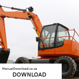
tands and lower the excavator back to the ground using the jack.

    – **Final Check**:
    – Inspect the installation to ensure everything is secure and properly aligned.
    – Start the excavator and perform a quick test drive to ensure that the sway bar link functions correctly without any unusual noises.

    – **Dispose of Old Parts**:
    – Properly dispose of the old sway bar links and any other removed components as per local regulations.

    ### Notes
    – Always refer to the specific service manual for the Case CX31B or CX36B for detailed instructions, torque specifications, and diagrams.
    – If unfamiliar with mechanical work or safety procedures, consider consulting a professional mechanic.
    The radiator cap is a crucial component of a vehicle’s cooling system, designed to maintain the proper pressure within the radiator. Typically made from metal or high-quality plastic, the radiator cap serves multiple important functions that contribute to the overall efficiency and functionality of the engine cooling process.

    One of the primary roles of the radiator cap is to create a seal for the cooling system, which allows it to maintain pressure. The cap is engineered to hold a specific pressure, usually indicated in pounds per square inch (psi). When the engine operates, the coolant heats up and expands, increasing the pressure within the system. The radiator cap features a pressure relief valve that opens at a predetermined pressure, allowing excess pressure to escape and preventing potential damage to the radiator and other components.

    Additionally, the radiator cap plays a role in the coolant recovery system. It allows coolant to flow into the overflow reservoir when the system is under pressure, and it creates a vacuum as the engine cools down, drawing coolant back into the radiator. This helps to ensure that the radiator is always filled with the proper amount of coolant, reducing the risk of overheating.

    Regular inspection and replacement of the radiator cap are essential, as a faulty or worn cap can lead to coolant leaks, overheating, and, ultimately, engine damage. Thus, the radiator cap, though often overlooked, is vital for maintaining the health and performance of a vehicle’s engine.

    Download SUBARU LEGACY LIBERTY 1990-1994 Service Repair Manual –

    owners manual
    Performing engine diagnostics on a Subaru Legacy (known as Liberty in some regions) typically involves several steps to identify and troubleshoot issues. click here for more details on the download manual…..


      Subaru Legacy Wagon Rear Strut Replacement Overview of rear strut replacement on 2005 Subaru Legacy 2.5i Limited wagon. If you like the vids and want to help make more: …

      2012-2019 Subaru Legacy Outback Transmission Fluid and Filter Change How To DIY PARTS LIST: ▪️ Fluid: Dealer ▪️ Filter: https://amzn.to/3AJvTbh TOOLS NEEDED: ▪️ Allen socket set: …

    Here is a reverse order of the process:

    ### 8. **Interpret diagnostic Codes**
    – Use the scanner to read the codes and reference a repair manual or online database to understand what each code means and how it relates to the symptoms you have observed.

    ### 7. **Clear diagnostic Codes (if necessary)**
    – If you want to reset the system after making repairs or to see if the code reappears, clear the codes using the scanner. Make sure to address any issues before doing this.

    ### 6. **Test Drive the Vehicle**
    – Take the car for a test drive under various conditions to see if the check engine light reappears and to confirm if any symptoms persist.

    ### 5. **Perform Visual Inspection**
    – Check for any obvious issues such as loose connections, damaged wires, or leaks. Look specifically at the engine components, hoses, and electrical connections.

    ### 4. **Check Live Data with the Scanner**
    – Use the diagnostic scanner to access live data from the engine sensors. Look for any readings that are out of the normal range, such as fuel trims, coolant temperature, and airflow readings.

    ### 3. **Connect the OBD-II Scanner**
    – Locate the OBD-II port, usually found under the dashboard near the steering column. Connect your diagnostic scanner to this port.

    ### 2. **Turn on the Ignition (without starting the engine)**
    – Turn the ignition key to the “ON” position (or press the start button without pressing the brake pedal) to power the vehicle’s electronics, enabling the scanner to communicate with the engine control module (ECM).

    ### 1. **Gather Necessary Tools**
    – Ensure you have the required tools: an OBD-II scanner, Basic hand tools for any necessary physical inspection,download SUBARU LEGACY LIBERTY workshop manual and a repair manual or access to online resources for Subaru diagnostics.

    By following these steps in reverse, you can effectively conduct engine diagnostics on a Subaru Legacy or Liberty. Always remember to consult specific service manuals for your model year for more detailed instructions and specifications.
    The windshield, also known as the front windscreen, is a crucial component of a vehicle that serves multiple essential functions. Primarily, it acts as a barrier against wind, debris, and weather elements, providing protection to the occupants from external conditions. Made from laminated safety glass, the windshield is designed to withstand impacts and prevent shattering, thereby enhancing passenger safety. In the event of an accident, a properly installed windshield helps to maintain the structural integrity of the vehicle’s cabin, preventing it from collapsing.

    Moreover, the windshield plays a vital role in the vehicle’s aerodynamics. Its design helps to reduce drag, thereby improving fuel efficiency and performance. Modern windshields are often equipped with features such as defrosters, which help to maintain visibility in adverse weather conditions, and sensors for rain detection that can automatically activate windshield wipers.

    In addition to these functional aspects, the windshield also contributes to the overall aesthetic of the vehicle, influencing its design and style. Advances in technology have led to the development of heated windshields and those with acoustic properties that reduce noise from the outside. Furthermore, many modern vehicles utilize advanced driver-assistance systems (ADAS) that rely on cameras and sensors mounted on or near the windshield, underscoring its multifaceted importance in contemporary automotive design and safety. Overall, the windshield is Not just a transparent barrier; it is a complex component integral to the vehicle’s functionality, safety, and comfort.

    Download 2005 Mercedes-Benz G-Class G400 Cabrio (W463) OEM Download Service & Repair Manual Software –

    service
    Repairing the shift interlock on a Mercedes-Benz G-Class G400 Cabrio (W463) involves several steps that require careful attention to detail. click here for more details on the download manual…..


      Is it a bad idea to buy a used Mercedes G W463? 5 reasons to buy and not to buy Mercedes G-Klasse W463.

      Fuse box location and diagrams: Mercedes-Benz G-Class (W463) See more on our website: https://fuse-box.info/mercedes-benz/mercedes-benz-g-class-w463-fuses-and-relay Fuse box diagram …

    The shift interlock system is designed to prevent the driver from shifting out of park without pressing the brake pedal. If this system malfunctions, it can prevent the vehicle from starting or shifting gears properly. Below is a detailed guide on how to repair the shift interlock system.

    ### Tools and Materials Needed
    1. **Tools:**
    – Screwdrivers (Phillips and flathead)
    – Torx screwdriver set
    – Socket set (including extensions)
    – Pliers
    trim removal tools
    – Multimeter (for testing electrical components)

    2. **Materials:**
    – Replacement parts (if needed, such as the interlock solenoid)
    – Electrical connectors (if damaged)
    – Lubricant (for moving parts)

    ### Step-by-Step Repair Process

    #### 1. Safety Precautions
    – **Disconnect the Battery:** Before starting any work, disconnect the negative terminal of the battery to prevent electrical shorts or accidental airbag deployment.

    #### 2. Access the Shift Interlock
    – **Remove the Center Console:**
    – Use trim removal tools to carefully pry up the center console trim surrounding the gear shifter. Be cautious to avoid damaging clips.
    – Remove screws or bolts holding the center console in place using the appropriate screwdriver or socket. Keep track of all screws and components removed.
    – Gently lift the center console to expose the shifter assembly and wiring underneath.

    #### 3. Inspect the Shift Interlock Mechanism
    – **Locate the Shift Interlock Solenoid:**
    – The shift interlock solenoid is typically mounted near the gear shifter assembly. Look for a small cylindrical component connected to the shifter mechanism.

    – **Check for Damage:**
    – Inspect the solenoid for any visible signs of damage or wear. Look for corrosion, broken wires, or mechanical obstruction.

    – **Test the Solenoid:**
    – Using a multimeter, check the solenoid for continuity. If there is no continuity, the solenoid may need to be replaced.

    #### 4. Repair or Replace Components
    – **Repairing the Shift Interlock:**
    – If the solenoid is operational but not functioning due to obstruction, clean any debris or lubrication that may be affecting its operation.
    – Ensure that the shift interlock lever is moving freely and not obstructed by other components.

    – **Replacing the Solenoid:**
    – If the solenoid is defective, carefully disconnect the wiring harness by releasing any clips or connectors.
    – Remove the solenoid from its mounting bracket, noting how it is installed for proper reassembly.
    – Install the new solenoid by reversing the removal steps and reconnecting the wiring harness securely.

    #### 5. Reassemble the Center Console
    – **Reinstall the Center Console:**
    – Carefully position the center console back into place, ensuring that all clips and mounts are aligned correctly.
    – Secure the center console with screws or bolts removed earlier.
    – Replace any detailed steps, you can successfully diagnose and repair the shift interlock system, ensuring your vehicle operates safely and efficiently. If you encounter significant issues or are unsure about specific components, it’s advisable to consult a professional mechanic or refer to the vehicle’s service manual for further guidance.
    The Mass Airflow Sensor (MAF) is a critical component in an internal combustion engine’s air intake system. Its primary function is to measure the amount of air entering the engine, which is essential for optimizing the air-fuel mixture. By providing accurate airflow data to the Engine Control Unit (ECU), the MAF sensor helps ensure that the engine operates efficiently and effectively, balancing performance, fuel economy, and emissions.

    Typically located between the air filter and the intake manifold, the MAF sensor can utilize various technologies, such as hot wire, hot film, or vane types. The hot wire MAF, for instance, consists of a thin wire heated by an electrical current. As air flows over the wire, it cools down; the ECU then calculates the airflow based on the amount of current needed to maintain the wire’s temperature. This measurement is crucial because the engine relies on precise air intake data to adjust the fuel injection accordingly.

    A malfunctioning MAF sensor can lead to various issues, including poor engine performance, rough idling, increased emissions, and reduced fuel efficiency. Common symptoms of MAF sensor problems may include check engine lights, stalling, or hesitation during acceleration. Regular maintenance and inspection of this component are vital for maintaining an engine’s overall health and performance.

    Download 2010 Chrysler Chrysler 300 Owners Manual –

    online
    Replacing a CV (Constant Velocity) joint on a Chrysler 300 can be a bit technical, but I will break it down into simple steps. click here for more details on the download manual…..


      How To: Replace The Ignition Switch On A 2005-2010 Chrysler 300 Brian Eslick from How to Automotive http://www.howtoautomotive.com/ takes you step-by-step through the process of replacing the …

      Roll down Chrysler 300 windows with key fob 2017 Chrysler 300S 5.7 Enable global windows down in AlfaOBD.

    Before you start, ensure you have the necessary tools and parts. You may want to consider having a repair manual specific to your vehicle for reference. Here’s a straightforward guide to help you through the process:

    ### Tools and Materials Needed:
    1. **Tools:**
    – Socket set (metric)
    – Wrench set
    – Pliers
    – Hammer
    – Screwdrivers (flathead and Phillips)
    – Torque wrench
    – Jack and jack stands
    – Pry bar (optional)
    – CV joint replacement kit (includes new CV joint and boot)

    2. **Safety Gear:**
    – Safety glasses
    – Gloves

    ### Steps to Replace a CV Joint:

    #### 1. **Preparation:**
    – **Park the Car:** make sure the car is on a flat surface.
    – **Disconnect the Battery:** For safety, disconnect the negative terminal of the battery.

    #### 2. **Lift the Car:**
    – Use the jack to lift the front of the car and place jack stands under the vehicle to secure it. Never work under a car supported only by a jack.

    #### 3. **Remove the Wheel:**
    – Use a socket wrench to remove the lug nuts on the wheel where the CV joint is located.
    – Take off the wheel and set it aside.

    #### 4. **Remove the Brake Components:**
    – Depending on the model, you may need to remove the brake caliper and rotor. Use a wrench to remove the caliper bolts and hang the caliper with a bungee cord (do not let it dangle from the brake line).
    – Remove the brake rotor if necessary.

    #### 5. **Access the CV Joint:**
    – Look for the axle nut (it’s usually in the center of the hub). Use a socket to remove this nut. You might need to hold the axle in place with a pry bar.
    – If your model has a hub assembly, you might need to remove it to access the CV joint. Use a wrench or socket to unscrew the bolts holding the hub.

    #### 6. **Remove the Old CV Joint:**
    – Once you can see the axle, carefully pull it out of the transmission or differential. You might need to tap it gently with a hammer to loosen it.
    – If the boot is torn or damaged, you can remove the old CV joint by cutting the boot and sliding it off.

    #### 7. **Install the New CV Joint:**
    – Slide the new CV joint onto the axle and push it back into the transmission or differential until it clicks into place.
    make sure to place a new boot over the CV joint and secure it with clamps (these usually come with the replacement kit).

    #### 8. **Reassemble Everything:**
    – Reinstall the axle nut and tighten it to the manufacturer’s specifications (check your repair manual for the exact torque).
    – If you removed the hub, reinstall it and secure it with bolts.
    – Reattach the brake rotor and caliper.
    – Put the wheel back ondownload Chrysler Chrysler 300 workshop manual and tighten the lug nuts.

    #### 9. **Lower the Car:**
    – Carefully remove the jack stands and lower the car back to the ground.

    #### 10. **Reconnect the Battery:**
    – Reattach the negative terminal of the battery.

    #### 11. **Test the Vehicle:**
    – Start the car and take a short drive to ensure everything is functioning properly. Listen for any unusual noises that might indicate an issue.

    ### Final Tips:
    – Always follow safety precautions when working on a car.
    – If you feel uncomfortable with any step, it’s a good idea to consult a professional mechanic.
    – Keep your workspace organized to avoid losing any small parts.

    By following these steps, you should be able to replace the CV joint on your Chrysler 300 with some patience and care. Good luck!
    A differential is a crucial component in a vehicle’s drivetrain that allows for the distribution of power to the wheels while enabling them to rotate at different speeds. This is particularly important for vehicles that turn corners, as the wheels on the outside of the turn need to travel a greater distance than those on the inside. Without a differential, the wheels would be forced to rotate at the same speed, leading to tire wear, loss of traction, and difficulty in maneuvering.

    Differentials are typically found in the rear axle of rear-wheel-drive vehicles and can also be located in the front axle of front-wheel-drive vehicles. Some vehicles may even have a differential on both axles, especially all-wheel-drive and four-wheel-drive models. The basic design of a differential consists of a series of gears housed in a casing, which allows for the necessary speed variation between the wheels.

    There are various types of differentials, including open differentials, limited-slip differentials, and locking differentials. Open differentials are the most common, providing basic functionality but sometimes leading to traction issues when one wheel slips. Limited-slip differentials, on the other hand, utilize friction to distribute torque more evenly between the wheels, enhancing traction. Locking differentials can be engaged manually or automatically to ensure both wheels turn at the same speed, which is particularly useful in off-road conditions.

    In summary, the differential is an essential component that enhances vehicle handling, stability, and performance, making it vital for safe and efficient driving.

    Download KOMATSU PC308USLC-3 Hydraulic Excavator Operation & Maintenance Manual –

    fix
    Repairing the gear shift linkage on a Komatsu PC308USLC-3 hydraulic excavator involves several steps and components. click here for more details on the download manual…..


      BMW 330xi Radiator Upgrade DIY (1999-2006 BMW E46 330i, 330Ci, 325i, 325xi, 325Ci, 328i, 328xi) Notorious for cooling system woes, the BMW E46 is just a few choice upgrades away from good reliability. One of the best things …

      KOMATSU PC308USLC-3 H48647 I created this video with the YouTube Video Editor (http://www.youtube.com/editor)

    Below is a detailed guide on how to carry out this repair. Please ensure to follow all safety guidelines and refer to the official Komatsu service manual for specific procedures and torque specifications.

    ### Safety Precautions:
    1. **Personal protective equipment (PPE)**: Wear gloves, safety glasses, and steel-toed boots.
    2. **Isolation**: Ensure the machine is turned off, the key is removed, and the hydraulic system is depressurized.
    3. **Stability**: Use appropriate support stands if the excavator is raised.

    ### Tools and Materials Needed:
    – **Tools**: Wrench set, socket set, screwdrivers, pliers, torque wrench, and possibly a gear puller.
    – **Replacement Parts**: New shift linkage components (if worn or damaged), gaskets, seals, and lubricants as necessary.
    – **Cleaning Supplies**: Degreaser, rags, and a small brush.

    ### Components of Gear Shift Linkage:
    1. **Gear Shift Lever**: The lever that the operator uses to change gears.
    2. **Linkage Rods**: These connect the gear shift lever to the transmission. They transmit the operator’s input to the transmission.
    3. **Ball Joints/Couplings**: Allow for movement between the linkage rods and the gear shift lever/transmission.
    4. **Mounting Brackets**: Secure the linkage components to the excavator chassis.
    5. **Bushings and Bearings**: Facilitate smooth movement of the linkage.
    6. **Return Springs**: Ensure the gear shift lever returns to its original position after shifting.

    ### Step-by-Step Repair Process:

    #### 1. **Inspect the Gear Shift Linkage:**
    – **Visual Inspection**: Check for any visible damage, wear, or loose connections in the gear shift linkage.
    – **Function Test**: Move the gear shift lever through its range of motion to identify any binding or unusual resistance.

    #### 2. **Remove the Gear Shift Lever:**
    – **Access the Lever**: Depending on the machine’s configuration, you may need to remove a cover or panel to access the gear shift lever.
    – **Detach the Lever**: Unscrew the mounting bolts holding the lever in place. Carefully lift the lever out, noting any washers or spacers used.

    #### 3. **Disconnect Linkage Rods:**
    – **Identify Linkage Points**: Locate the points where the rods connect to the gear shift lever and transmission.
    – **Remove the Couplings**: Use pliers or a wrench to detach the ball joints or couplings. Be mindful of any retaining clips that may need to be removed first.
    – **Take Note of Orientation**: Document the orientation and configuration of the linkage rods for reinstallation.

    #### 4. **Inspect and Replace Components:**
    – **Examine each Component**: Look for wear or damage on the rods, bushings, and joints. If any parts are damaged, replace them with new ones.
    – **Clean Parts**: Use a degreaser to clean all components before reassembly.

    #### 5. **Reassemble the Linkage:**
    – **Install New Components**: If any components were replaced, install them in the reverse order of removal.
    – **Reconnect Linkage Rods**: Attach the rods back to the gear shift lever and transmission, ensuring they are secured tightly.
    – **Check Alignment**: Make sure that all components are aligned correctly to prevent binding.

    #### 6. **Reinstall the Gear Shift Lever:**
    – **Position the Lever**: place the lever back in its original position, ensuring any spacers or washers are correctly placed.
    – **Secure the Lever**: Tighten the mounting bolts to the specified torque using a torque wrench.

    #### 7. **Test the Gear Shift Mechanism:**
    – **Function Check**: Before starting the excavator, manually move the gear shift lever to ensure it shifts smoothly through all positions.
    – **Start the Engine**: With the machine in neutral, start the enginedownload KOMATSU PC308USLC 3 Hydraulic Excavator Operation workshop manual 
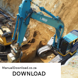
and test the gear shifting under operational conditions.
    – **Observe for Issues**: Pay attention to any unusual noises or resistance during operation.

    #### 8. **Final Inspection:**
    – **Check for Leaks**: After testing, check around the gear shift linkage area for any fluid leaks.
    – **Ensure Proper Operation**: confirm that the gear changes are smooth and responsive.

    ### Conclusion:
    Repairing the gear shift linkage on a Komatsu PC308USLC-3 requires attention to detail and a systematic approach. Proper inspection, replacement of components, and reassembly according to specifications are crucial for ensuring the excavator operates efficiently. Always consult the manufacturer’s service manual for detailed instructions tailored to your specific model.
    The hood release is a crucial component in automotive design, functioning as a mechanism that allows the driver or a technician to open the vehicle’s hood with ease. Typically located inside the passenger compartment, often near the driver’s seat, the hood release consists of a lever or a pull cord connected to a latch on the hood itself. When the driver pulls the lever or cord, it activates the latch mechanism that secures the hood, disengaging it and allowing it to be lifted for access to the engine compartment.

    The design and placement of the hood release are important for both convenience and safety. It is usually designed to be easily accessible, allowing for quick access when checking engine fluids, inspecting the battery, or performing routine maintenance. In many vehicles, an additional safety catch is integrated into the hood release system to prevent accidental opening while driving, requiring a second action to fully lift the hood.

    In modern vehicles, the hood release mechanism may also include electronic components, particularly in cars with advanced features such as remote start systems or keyless entry. Regular maintenance of the hood release is essential, as wear or corrosion can impede its functionality, making it difficult to open the hood when necessary. Overall, the hood release plays a significant role in vehicle maintenance and functionality, ensuring that drivers and technicians can easily access the engine compartment for necessary inspections and repairs.

    Download 1999 BMW 328Ci (E46) 3 Series Coupe OEM Download Service & Repair Manual Software –

    book shop
    Performing engine diagnostics on a BMW 328Ci E46 (produced between 1998 and 2006) can seem daunting if you have little mechanical experience, but it can be broken down into simpler steps. click here for more details on the download manual…..


      BMW 330xi Radiator Upgrade DIY (1999-2006 BMW E46 330i, 330Ci, 325i, 325xi, 325Ci, 328i, 328xi) Notorious for cooling system woes, the BMW E46 is just a few choice upgrades away from good reliability. One of the best things …

      Best first mod for your E46 For POV drive video with all these mods (great sound): https://youtu.be/7N_eKKEVMzg I installed ebay headers and aside from a …

    Here’s a straightforward guide to help you understand the process.

    ### Tools You’ll Need:
    1. **OBD-II Scanner**: This device reads diagnostic trouble codes (DTCs) from the car’s computer.
    2. **Basic Hand Tools**: Screwdrivers, wrenches, and pliers (for minor repairs).
    3. **Notebook and Pen**: To jot down any codes or observations.

    ### Step-by-Step Guide to Engine Diagnostics

    #### 1. **Check Engine Light**
    – Before diving into diagnostics, look for the **Check Engine Light** (CEL) on your dashboard. If it’s illuminated, this indicates that there’s an issue that needs to be addressed.

    #### 2. **Locate the OBD-II Port**
    – The OBD-II port is usually located under the dashboard, near the driver’s side, just above the pedals. It’s a small, rectangular connector.

    #### 3. **Connect the OBD-II Scanner**
    – Plug the scanner into the OBD-II port. Ensure your vehicle is off when you do this.
    – Turn the ignition key to the “ON” position without starting the engine (you may need to press the start button if your model has one).

    #### 4. **Read Diagnostic Codes**
    – Follow the instructions on your OBD-II scanner to retrieve the codes.
    – The scanner will display a series of codes; these are the Diagnostic Trouble Codes (DTCs) that indicate specific issues with the engine or other systems.

    #### 5. **Interpret the Codes**
    – Once you have the codes, look them up in the scanner’s manual or use online resources to understand what each code means. Common codes might relate to sensors, fuel systems, or ignition problems.

    #### 6. **Visual Inspection**
    – While you’re at it, perform a basic visual inspection of the engine bay:
    – Look for any loose or damaged wires.
    – Check for leaks (oil, coolant, etc.).
    – Make sure all hoses are connected securely.
    – Inspect belts for wear.

    #### 7. **Research and Troubleshoot**
    – Based on the codes retrieved and your visual inspection, research potential fixes. Forums for BMW enthusiasts can be helpful.
    – Many issues can be resolved by replacing faulty sensors, cleaning parts, or tightening connections.

    #### 8. **Clear Codes (if applicable)**
    – After addressing the issues, you can clear the codes using your scanner. This will reset the CEL.
    – Monitor the dashboard for the CEL to see if it returns. If it does, the issue may not have been fully resolved.

    #### 9. **Test Drive**
    – Take your car for a short drive to see if the CEL comes back on. This will help confirm whether the issue has been fixed.

    ### When to Seek Professional Help
    If you retrieve codes that are complex or if the CEL returns after your efforts, it might be time to consult a professional mechanic. They have more specialized toolsdownload BMW 328Ci E46 3 Coupe OEM workshop manual and expertise to diagnose and address serious issues.

    ### Conclusion
    While engine diagnostics on a BMW 328Ci E46 can seem intimidating, following these steps can help you identify and possibly resolve issues. Always prioritize safety, and don’t hesitate to seek professional help if needed.
    A fuel injector is a critical component of modern internal combustion engines, playing a vital role in the engine’s performance and efficiency. Its primary function is to deliver the precise amount of fuel into the combustion chamber at the correct time, ensuring optimal combustion. Unlike older carburetor systems, which mix air and fuel mechanically, fuel injectors use electronic controls to achieve a more accurate and efficient fuel-air mixture, enhancing overall engine performance.

    Fuel injectors are typically composed of a nozzle, a solenoid or piezoelectric actuator, and a fuel passage. When the engine’s control unit (ECU) signals the injector, the actuator opens the nozzle, allowing fuel to spray into the intake manifold or directly into the combustion chamber, depending on the type of fuel injection system used—either port fuel injection (PFI) or direct fuel injection (DFI). The injector’s design allows for various spray patterns and atomization levels, which are crucial for ensuring complete combustion and minimizing emissions.

    The performance of fuel injectors is influenced by several factors, including the fuel type, engine speed, and load conditions. Over time, injectors can become clogged or malfunction, leading to engine misfires, reduced fuel efficiency, and increased emissions. Regular maintenance and cleaning can help ensure injectors function optimally, making them essential for the longevity and efficiency of an engine. In summary, fuel injectors are fundamental components that enable engines to operate efficiently, meet regulatory standards, and provide the performance drivers expect.