Download 1981 BMW 528i (E12) 5 Series OEM Download Service & Repair Manual Software –

fix
Performing a wheel alignment on a BMW 528i E12 requires specific tools and a detailed understanding of the process. click here for more details on the download manual…..


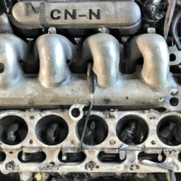
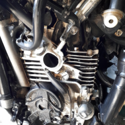
    Inside Engine Block BMW 5 Series 3 Series E90 E39 528I 328I M5 M3 I Will Greatly Appreciate If You Can Give My Video Thumbs Up And Subscribe To See Future Videos Thank You Very Much …

    How To Remove the Front Differential on BMW xDrive F10 F01 | BOND Garage In this video I’ll show you how to easily remove the front differential on a BMW F10 and also how to remove the front drive shafts in …

Here’s a step-by-step guide with descriptions of the necessary tools:

– **Tools and Equipment:**
– **Alignment Machine:** A professional alignment machine provides precise measurements of camber, caster, and toe angles. Look for one that is compatible with the E12 model.
– **Jack and Jack Stands:** A hydraulic floor jack is needed to lift the vehicle, and jack stands are essential for safety when working underneath the car.
– **Wheel Chocks:** These prevent the vehicle from rolling while it is lifted and ensure safety during the process.
– **Tire Pressure Gauge:** Checking and adjusting tire pressure is crucial before starting the alignment. Properly inflated tires can affect alignment readings.
– **Torque Wrench:** This tool is used to ensure that bolts are tightened to the manufacturer’s specifications, particularly when adjusting suspension components.
– **Alignment Tools (Camber/Caster Gauge):** Used for manual measurements of camber and caster angles if the alignment machine is not available.
– **Adjustable Wrenches and Socket Set:** Essential for loosening and tightening bolts on the suspension components during adjustments.
– **Ruler or Measuring Tape:** For measuring toe settings, if necessary, during the alignment process.

– **Preparation:**
– **Inspect Tires:** check for uneven wear patterns that may indicate existing alignment issues. Replace or rotate tires if necessary.
– **Check Suspension Components:** Before performing an alignment, inspect suspension components (tie rods, control arms, bushings) for wear or damage, as these can affect alignment.
– **Set Tire Pressure:** Ensure all tires are inflated to the recommended pressure as per the manufacturer’s specifications.

– **Setting Up the Vehicle:**
– **Lift the Vehicle:** Use the hydraulic jack to lift the front of the BMW 528i E12 and secure it with jack stands.
– **Install Wheel Chocks:** Place wheel chocks behind the rear wheels to prevent any movement.

– **Alignment Process:**
– **Mount Alignment Equipment:** attach the alignment machine’s sensors to the wheels according to the manufacturer’s instructions.
– **Measure Initial Angles:** Use the alignment machine to measure the current camber, caster, and toe angles. Note these readings for reference.
– **Adjust Toe Settings:**
– Locate the tie rod ends and loosen the lock nuts.
– Adjust the tie rods to modify the toe angle as needed. The desired toe setting for the E12 will be specified in the service manual.
– Once adjusted, use the torque wrench to tighten the lock nuts to the specified torque.

– **Adjust Camber and Caster:**
– **Camber Adjustment:** This may involve adjusting the upper control arms or camber plates. Follow the specific procedure outlined in the service manual.
– **Caster Adjustment:** on some models, caster may be adjusted using the lower control arm. Ensure adjustment is made per the specifications.

– **Final Measurements:**
– **Recheck Angles:** After all adjustments, use the alignment machine to measure the angles again. Ensure they are within the manufacturer’s specified range.
– **Road Test:** After the alignment is complete, take the vehicle for a short drive to ensure that it tracks straightdownload BMW 528i E12 5 OEM workshop manual and does not pull to one side.

– **Documentation:**
– **Record the Results:** Document the before and after alignment specifications for future reference. This can help in diagnosing any future alignment or suspension issues.

– **Regular Maintenance:**
– **Schedule Regular Alignments:** Regular checks every 6,000 miles or when tire wear is noticed can help maintain proper alignment and prolong tire life.

By following these steps and using the appropriate tools, you can perform a successful wheel alignment on a BMW 528i E12. Always refer to the vehicle’s service manual for specific specifications and procedures to ensure accuracy and safety.
An air filter is a crucial component of an internal combustion engine, designed to ensure that the air entering the engine is clean and free from contaminants. Located between the air intake and the engine, the air filter plays a vital role in maintaining optimal engine performance and longevity. Its primary function is to trap dust, dirt, pollen, and other particulate matter from the air before it mixes with fuel for combustion.

The design of an air filter typically consists of a pleated paper or foam material housed within a plastic or metal frame. The pleats increase the surface area, allowing for greater dirt-holding capacity and improved airflow. A clean air filter allows the engine to breathe efficiently, promoting better combustion, which translates to improved power output, fuel efficiency, and reduced emissions. Conversely, a clogged or dirty air filter can restrict airflow, leading to poor engine performance, increased fuel consumption, and potential engine damage over time.

Regular maintenance of the air filter is essential, as it can become saturated with debris and lose its effectiveness. Depending on driving conditions and vehicle usage, air filters should be inspected and replaced periodically, typically every 12,000 to 15,000 miles. In modern vehicles, some models are equipped with reusable or washable air filters that can be cleaned and reinstalled. Overall, the air filter is a small yet significant component that plays a critical role in the overall health and efficiency of an engine.

Download Case 580N, 580SN, 580SN WT, 590SN Service Manual –

book store
Repairing a suspension spring seat on a Case 580N, 580SN, 580SN WT, or 590SN backhoe can be a complex task, but I’ll break it down into simpler steps to help you understand the process even if you have little mechanical experience. click here for more details on the download manual…..


      Case 580NEP diagnostics for a crank but no start after a new engine harness

    Before starting, always remember to prioritize safety by wearing appropriate protective gear, including gloves and safety glasses.

    ### Tools and Materials Needed:
    1. **Tools:**
    – Wrenches or socket set
    – Screwdrivers
    – Pliers
    – Hammer
    – Jack and jack stands (or a lift if available)
    torque wrench

    2. **Materials:**
    – Replacement suspension spring seat (make sure it’s the right part for your model)
    – Lubricant (like grease)
    cleaning supplies (rags, degreaser)

    ### Step-by-Step Guide:

    #### Step 1: Safety First
    – Ensure the machine is on a flat surface and the parking brake is engaged.
    – Turn off the engine and remove the key from the ignition.

    #### Step 2: Lift the Machine
    – Use a jack to lift the rear of the backhoe. Once it’s elevated, place jack stands underneath to secure it. This is crucial for your safety while working.

    #### Step 3: Remove the Wheel (if necessary)
    – Depending on your access to the suspension spring seat, you may need to remove the rear wheel. Use a wrench or socket to remove the lug nuts, and then take off the wheel.

    #### Step 4: Locate the suspension Spring Seat
    – Identify the suspension spring seat, which is typically a metal component that supports the spring and connects to the chassis of the backhoe.

    #### Step 5: Remove the Old Spring Seat
    – Look for bolts or screws holding the old spring seat in place. Use your wrench or socket to remove these fasteners.
    – If the seat is rusted or stuck, you may need to gently tap it with a hammer or use a penetrating oil to loosen it.

    #### Step 6: Clean the Area
    – Once the old spring seat is removed, clean the area where it was mounted. Use a rag and degreaser to remove dirt, grease, and debris. This will ensure a good fit for the new seat.

    #### Step 7: Install the New Spring Seat
    – Position the new suspension spring seat in the same location as the old one.
    – Align the holes and insert the bolts or screws you removed earlier. Hand-tighten them first.

    #### Step 8: tighten Everything Securely
    – Using a torque wrench, tighten the bolts to the manufacturer’s specifications (you can find this information in the machine’s manual). This ensures everything is securedownload Case 580N 580SN 580SN WT 590SN workshop manual and prevents future issues.

    #### Step 9: Reattach the Wheel
    – If you removed the wheel, place it back on the axle and hand-tighten the lug nuts. Lower the machine to the ground and then fully tighten the lug nuts in a crisscross pattern to ensure even pressure.

    #### Step 10: Lower the Machine and Test
    – Remove the jack stands and carefully lower the machine back to the ground.
    start the engine and check for any unusual noises or issues. Take the machine for a short test drive to ensure the suspension functions properly.

    ### Conclusion
    You have successfully repaired the suspension spring seat on your Case backhoe! Regular maintenance and inspections can help prevent future issues. If you ever feel unsure or uncomfortable with any step, consult a professional mechanic or refer to the service manual specific to your model for further guidance.
    The light switch in a vehicle is a crucial component of the automotive lighting system, responsible for controlling the operation of various lights, including headlights, taillights, turn signals, and interior illumination. Typically located on the steering column or dashboard, the light switch allows the driver to easily toggle between different lighting modes, ensuring optimal visibility and safety while driving.

    Modern light switches may come in various designs, often featuring multiple settings such as “off,” “parking lights,” “low beam,” and “high beam.” Some switches are also equipped with automatic functions that can detect ambient light conditions and adjust the headlights accordingly. This feature enhances convenience and safety, as it automatically turns the headlights on during dusk or inclement weather.

    In addition to standard lighting functions, many light switches also control auxiliary lights, such as fog lights, which improve visibility in adverse weather conditions. Some advanced vehicles may include additional features like daytime running lights (DRLs) and adaptive lighting systems that adjust the beam pattern based on the vehicle’s speed and steering angle.

    The light switch is not just a simple toggle; it is an integral part of a vehicle’s electrical system, often connected to fuses and relays that manage the power distribution to various lighting circuits. A malfunctioning light switch can lead to lighting failures, which can compromise safety, making it essential for drivers to ensure that their vehicle’s lighting system is functioning correctly. Regular checks and maintenance of the light switch and associated wiring can help prevent issues and ensure a safe driving experience.

    Download BMW 528i 2002 Factory Service Repair Manual –

    australian
    Certainly! click here for more details on the download manual…..


      BILSTEIN B6 installation // BMW F10 5-Series In this video, we share the importance of regularly checking the health and condition of your car’s shock-absorbers, as well as chat …

      Buying a Used BMW 5 Series – Everything you need to know! http://www.workingwithbrian.com – Buying a Used BMW 5 Series If you’re in the market to buy a used 5 series, let me help you …

    Replacing the ignition coil on a BMW 528i involves several steps. Below is a detailed guide with bullet points for clarity.

    ### Tools and materials Needed:
    – **Socket Set**: A set of metric sockets (10mm, 12mm, etc.) for various bolts and fasteners.
    – **Ratchet and Extension**: To reach deep-seated bolts comfortably.
    – **Torque Wrench**: To ensure bolts are tightened to the manufacturer’s specifications.
    – **Flathead Screwdriver**: Useful for prying up connectors or clips.
    – **Pliers**: To remove any electrical connectors or clips safely.
    – **Wire Brush or Sandpaper**: For cleaning any corrosion on terminals.
    – **New Ignition Coils**: Ensure you have the correct coils for your BMW model.
    – **Dielectric Grease**: To prevent moisture and corrosion on the electrical connectors.
    – **Safety Glasses and Gloves**: To protect your eyes and hands during the process.
    – **Service Manual**: For torque specifications and any specific details relevant to your vehicle.

    ### Procedure:
    – **Safety First**:
    – Park the car on a level surface and engage the parking brake.
    – Disconnect the negative battery terminal to prevent any electrical shorts or shocks.

    – **Remove Engine Cover**:
    – If applicable, use a socket to remove any bolts holding the engine cover in place.
    – Carefully lift the cover off and set it aside.

    – **Identify Ignition Coils**:
    – Locate the ignition coils on the engine. they are usually positioned on top of the engine near the spark plugs.
    – The BMW 528i may have multiple coils depending on the engine configuration.

    – **Disconnect electrical Connectors**:
    – Firmly grasp the connector on each ignition coil and gently pull to disconnect it.
    – If necessary, use a flathead screwdriver to release any locking tabs.

    – **Remove Ignition Coils**:
    – Use a socket to remove the bolts securing each ignition coil in place.
    – Carefully pull the ignition coil straight out of the spark plug tube. If it’s stuck, gently twist it back and forth to loosen it.

    – **Inspect and Clean**:
    – Check the old ignition coils for any signs of damage or wear.
    – Use a wire brush or sandpaper to clean any corrosion from the spark plug area and the coil connectors.

    – **Install New Ignition Coils**:
    – Apply a small amount of dielectric grease to the inside of the new ignition coil connector to prevent moisture ingress.
    – Insert the new ignition coil into the spark plug tube until it sits flush.
    – Secure it in place with the bolts removed earlier, tightening them to the manufacturer’s specifications using a torque wrench.

    – **Reconnect electrical Connectors**:
    – Firmly press the electrical connector onto the new ignition coil until it clicks into place.
    – Ensure that each connector is securely attacheddownload BMW 528i workshop manual and that there are no loose wires.

    – **Reinstall Engine Cover**:
    – If an engine cover was removed, place it back onto the engine and secure it with the bolts.

    – **Reconnect Battery**:
    – Reconnect the negative battery terminal and ensure it is tightened securely.

    – **Test the Vehicle**:
    – Start the engine to check if it runs smoothly without any warning lights illuminated on the dashboard.
    – Listen for any unusual noises and ensure the engine is running properly.

    ### Final Checks:
    – **Dispose of Old Parts**: Properly dispose of or recycle the old ignition coils as per local regulations.
    – **Keep Records**: Note the date and mileage of the replacement for future reference.

    By following these steps, you should be able to successfully replace the ignition coils in your BMW 528i. Always refer to the vehicle’s service manual for any specific instructions or torque specifications.
    A jack is a crucial automotive tool designed to lift vehicles, providing access to the undercarriage for maintenance or repairs. It operates on the principle of mechanical advantage, allowing users to raise heavy loads with relative ease. There are various types of jacks, including hydraulic jacks, scissor jacks, and floor jacks, each suited for specific applications.

    Hydraulic jacks utilize fluid pressure to lift the vehicle, making them highly efficient and capable of raising heavier vehicles, such as trucks or SUVs. they consist of a pump mechanism that pushes hydraulic fluid into a cylinder, raising a piston connected to a lifting platform. Floor jacks, often seen in auto shops, are designed for stability and ease of use, featuring a long handle for leverage. Scissor jacks, commonly included with vehicles for emergency tire changes, are compact and rely on a cranking mechanism to lift the vehicle in a more vertical manner.

    Safety is paramount when using a jack; it is essential to use jack stands to secure the vehicle once it is lifted, preventing accidental falls. Understanding the weight capacity and proper usage of a jack is critical for both amateur and professional mechanics. Overall, jacks play an indispensable role in vehicle maintenance, enabling tasks such as tire changes, brake repairs, and inspections of the undercarriage.

    Download NEW HOLLand LS120 LS125 Skid Steer Loader Operators Manual –

    do your own repairs
    Replacing the fuel filter on a Holland LS120 or LS125 skid steer loader is an important maintenance task that helps ensure the engine runs smoothly and efficiently. click here for more details on the download manual…..


      A Skid-Steer Blueprint to Value This infographic shows the skid-steer options and attachments as well as equipment valuations.

    Below is a step-by-step guide that outlines the components involved and the procedure for replacing the fuel filter.

    ### Tools and Materials Needed

    1. **New Fuel Filter**: Ensure you have the correct fuel filter compatible with the LS120 or LS125.
    2. **Wrenches/Sockets**: Typically, you will need a combination of wrenches or sockets (usually metric) to remove the filter.
    3. **Fuel Line Clamps**: Optional, to prevent fuel spillage.
    4. **Rags/Paper Towels**: For cleaning up any spilled fuel.
    5. **Container for Fuel**: To catch any fuel that may spill during the process.
    6. **Safety Glasses**: To protect your eyes when working with fuel.

    ### Steps for Fuel Filter Replacement

    #### 1. Safety Precautions
    – **Park the Skid Steer**: Ensure the skid steer is on a flat surface and turned off.
    – **Engage the Parking Brake**: This is crucial to prevent any movement during the procedure.
    – **Wait for Components to Cool**: If the engine has been running, allow it to cool to avoid burns.

    #### 2. Locate the Fuel Filter
    – **Find the Fuel Filter**: The fuel filter is usually located near the fuel tank, along the fuel line leading to the engine. Consult the owner’s manual for the exact location if needed.

    #### 3. Prepare for Removal
    – **Relieve Fuel Pressure**: Before removing the fuel filter, relieve any fuel pressure in the system. This can typically be done by loosening the fuel cap on the tank.
    – **Place the Container**: Position the container underneath the filter to catch any spilled fuel.

    #### 4. Remove the Old Fuel Filter
    – **Disconnect Fuel Lines**: Using your wrenches, carefully loosen and disconnect the fuel lines from the filter. If fuel clamps are present, you might need to slide them back or remove them entirely.
    – **Remove the Filter**: Once the lines are disconnected, unscrew the filter from its mounting. Some filters may have a bracket that will need to be unbolted.

    #### 5. Prepare the New Fuel Filter
    – **Check the New Filter**: Before installation, compare the new filter with the old one to ensure it is the correct part.
    – **Apply Fuel to the New Filter**: It can be beneficial to fill the new filter with clean diesel fuel. This helps to minimize air in the system when you start the engine.

    #### 6. Install the New Fuel Filter
    – **Install the Filter**: Screw the new fuel filter into place, ensuring it is tight but not over-tightened to avoid damage.
    – **Reconnect Fuel Lines**: Reattach the fuel lines to the new filter. Make sure they are securely fastened and that any clamps are reattached.

    #### 7. Check for Leaks
    – **Inspect Connections**: Before starting the engine, visually inspect all connections to ensure they are tight and secure.
    – **Start the Engine**: Turn on the skid steerdownload HOLLand LS120 LS125 Skid Steer Loader s workshop manual and let it run for a few minutes. Check for any leaks around the new fuel filter and connections.
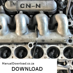
    #### 8. Clean Up
    – **Dispose of Old Filter**: Dispose of the old fuel filter in accordance with local regulations.
    – **Clean Up Spills**: Wipe up any spilled fuel with rags and dispose of them properly.

    ### Conclusion
    Regularly replacing the fuel filter is essential for maintaining the performance of your Holland LS120 or LS125 skid steer loader. Following these steps ensures a proper replacement and helps prevent contamination in the fuel system, which can lead to engine issues down the line. Always refer to the operator’s manual for specific Instructions or specifications related to your skid steer model.
    The blower motor is a crucial component in a vehicle’s heating, ventilation, and air conditioning (HVAC) system. Its primary function is to circulate air within the cabin of the car, ensuring that occupants remain comfortable regardless of external weather conditions. The blower motor is typically located within the dashboard, close to the heater core and evaporator, which are essential for heating and cooling the air, respectively.

    When the driver or passengers adjust the climate control settings, the blower motor activates to draw air from outside or recirculate interior air. It can operate at various speeds, allowing for customizable airflow. This is essential not only for comfort but also for defogging or defrosting windows, as it helps maintain visibility in adverse weather conditions.

    The blower motor is powered by electricity, often controlled by a resistor or electronic module that regulates its speed. Over time, components like the motor itself or the resistor may wear out, leading to issues such as a lack of airflow, unusual noises, or a complete failure to operate. Regular maintenance of the HVAC system, including checking the blower motor, is essential for ensuring optimal performance and comfort in the vehicle. A properly functioning blower motor plays a vital role in enhancing the overall driving experience, making it a key element of automotive design.

    Download Cummins Service Diesel Engine N14 Series Manual Workshop Service Repair Manual –

    repair
    Repairing the shift drum on a Cummins N14 engine can sound complex, especially if you’re not familiar with mechanical work. click here for more details on the download manual…..


      CUMMINS N14 EXHAUST VALVE SEAT New product, outer diameter 51mm, inner diameter 43mm, width 7mm, thickness 4mm.

      N14 Cummins Diesel Engine + Broken 18 Speed Transmission on Western Star Big N14 Cummins Diesel Engine in this western star Dump truck with broken 18 speed transmission. I show you as a heavy duty …

    However, I’ll explain the process step by step in simple terms. Remember, safety is paramount, so make sure to wear appropriate safety gear and, if possible, consult a professional mechanic if you’re unsure.

    ### What is the Shift Drum?

    The shift drum is a component in the engine’s transmission system. It helps in engaging and disengaging the gears, allowing the engine to shift properly as the vehicle moves.

    ### Tools and Materials Needed

    Before you start, gather the following tools and materials:

    1. **Basic hand Tools**: Wrenches, sockets, screwdrivers
    2. **Torque Wrench**: To ensure you tighten bolts to the right specifications
    3. **Replacement Parts**: Any gaskets or seals that might need replacing
    4. **Clean Rags**: For cleaning parts and wiping off oil
    5. **Engine Oil**: If needed for lubrication during reassembly
    6. **Service Manual**: A manual specific to the Cummins N14 for reference

    ### Steps to Repair the Shift Drum

    1. **Safety First**: Ensure the engine is turned off and cool. Disconnect the battery to prevent any electrical issues.

    2. **Access the Transmission**: Depending on your vehicle, you may need to remove parts like the transmission cover or access panels. This can involve unscrewing bolts and carefully lifting off panels.

    3. **Inspect the Shift Drum**: Once you have clear access, look at the shift drum closely. Check for signs of wear, cracks, or damage. If there are visible issues, it may need to be replaced.

    4. **Remove the Shift Drum**:
    – **Disconnect Linkages**: Before taking out the shift drum, disconnect any linkages (metal rods or cables) that connect it to the transmission.
    – **Unscrew Bolts**: Use the appropriate size socket to remove the bolts holding the shift drum in place. Keep these bolts organized for reinstallation.
    – **Take Out the Drum**: Once the bolts are removed, gently lift the shift drum out of its housing. Be careful not to drop any pieces.

    5. **Clean the Area**: Before installing a new drum or repairing the old one, clean the area around where the drum sits. Use a clean rag to wipe away any oil or debris.

    6. **Install Replacement or Repair**:
    – If you’re replacing the drum, simply place the new one in the same position as the old one.
    – If you’re repairing, follow the specific procedures outlined in your service manual for fixing any issues, which may involve replacing small parts or seals.

    7. **Reattach Everything**:
    – **Reconnect Linkages**: Ensure that all the linkages are properly connected to the shift drum.
    – **Bolt it Down**: Use your torque wrench to tighten the bolts to the specifications found in the service manual. This is important to ensure everything is secure.

    8. **Final Checks**: Double-check that everything is connected properlydownload Cummins Engine N14 workshop manual and that there are no leftover parts.

    9. **Reattach the Transmission Cover**: If you removed any covers, put them back in place and secure them with bolts.

    10. **Reconnect the Battery**: Once everything is back together, reconnect the battery.

    11. **Test the Engine**: Start the engine and check for proper shifting. If everything is working smoothly, you’re good to go!

    ### Conclusion

    Repairing the shift drum on a Cummins N14 engine requires careful attention to detail and a bit of mechanical knowledge. Always consult your vehicle’s service manual for specific instructions or specifications. If you feel uncomfortable at any point, it’s a good idea to call in a professional mechanic. Good luck!
    The camshaft is a crucial component in an internal combustion engine, responsible for controlling the timing and operation of the engine’s valves. It is a cylindrical rod that has multiple lobes, each shaped to push against the engine’s valve lifters or rockers. As the camshaft rotates, the lobes push open the intake and exhaust valves at specific intervals, allowing air and fuel to enter the combustion chamber and exhaust gases to exit.

    Typically made of steel or cast iron, the camshaft must endure significant stress and heat, necessitating robust materials and precise engineering. The position and timing of the camshaft are vital for the engine’s performance, efficiency, and emissions. In most engines, the camshaft is driven by the crankshaft via a timing belt or chain, ensuring that the opening and closing of the valves are synchronized with the movement of the pistons.

    There are two primary types of camshafts: overhead cam (OHC) and cam-in-block designs. OHC configurations, which can be single or double overhead cam (SOHC or DOHC), are increasingly popular in modern engines due to their potential for better airflow and performance. Advanced systems like variable valve timing (VVT) allow for further optimization of valve timing, enhancing efficiency and power across different engine speeds. Overall, the camshaft plays a pivotal role in the engine’s overall functionality, directly influencing performance characteristics and fuel efficiency.

    Download Hitachi Zaxis 200 230 270 Excavator Service Repair Manual –

    bookshop
    Replacing a torque converter on a Hitachi Zaxis 200, 230, or 270 excavator is a complex task that requires mechanical knowledge and experience. click here for more details on the download manual…..


      2007 Hitachi 270

      Hitachi hydraulic pump repairing and lapping hitachi #hydraulicpump #repairing #lapping.

    Below is a reverse order outline of the steps involved in the replacement process. It’s crucial to consult the specific service manual for your model for detailed instructions and safety precautions.

    ### Reverse Order Steps for Torque Converter Replacement

    1. **Reinstall the Torque Converter**
    – Align the torque converter with the transmission input shaft and carefully slide it into place.
    – Ensure that it is seated correctly and that the mounting bolts are accessible.

    2. **Reattach the Transmission**
    – Lift the transmission back into position and align it with the torque converter.
    – Secure the transmission with bolts, ensuring they are torqued to the manufacturer’s specifications.

    3. **Reconnect the Torque Converter Lines**
    – Reconnect any hydraulic lines or hoses to the torque converter. Ensure they are secure and free of leaks.

    4. **Install the Flex Plate**
    – If applicable, install the flex plate to the back of the engine and torque it to specifications.
    – Verify that the flex plate is aligned properly with the torque converter.

    5. **Reinstall the Engine Oil Pan**
    – If you removed the oil pan, reinstall it using a new gasket and torque the bolts to the specified settings.

    6. **Reconnect Electrical Connectors**
    – Reconnect any electrical connectors that were removed during the disassembly process.

    7. **Reinstall Exhaust Components**
    – If any exhaust components were removed, reinstall them securely.

    8. **Remove Engine Support**
    – If you used an engine support to hold the engine in place, carefully remove it.

    9. **Lower the Excavator**
    – If the excavator was raised for access, lower it back down to a stable position.

    10. **Drain Fluids**
    – Drain the transmission fluid and any other fluids that may interfere with the replacement process.

    11. **Remove the Old Torque Converter**
    – Disconnect the torque converter from the engine and transmission.
    – Remove the mounting bolts and carefully pull the old torque converter out.

    12. **Access the Torque Converter**
    – Depending on your model, you may need to remove the engine or transmission cover to access the torque converter.

    13. **Prepare for Replacement**
    – Before installing the new torque converter, inspect the mounting surfaces and clean any debris or old gasket material.

    ### Important Notes:
    – **Safety Precautions:** Always follow safety guidelines, including using appropriate personal protective equipment (PPE)download Hitachi Zaxis 200 230 270 Excavator workshop manual and ensuring the machine is stable during the procedure.
    – **Consult the Manual:** The specific service manual for your Hitachi Zaxis model will provide detailed torque specifications, diagrams, and additional steps specific to your machine.
    – **Fluid Replacement:** After the installation, refill the transmission and torque converter with the appropriate type and quantity of fluid.

    By following these reverse steps, you can systematically understand the process of torque converter replacement on a Hitachi Zaxis excavator. Always prioritize safety and consult professionals if you are unsure about any steps.
    A coil spring is a mechanical component widely used in various applications, most notably in the suspension systems of vehicles. It is designed in a helical shape, allowing it to compress and extend under load, providing a combination of flexibility and resistance. Coil springs are typically made from high-carbon steel or other durable materials to withstand the stresses and strains they encounter during operation.

    The primary function of a coil spring in automotive applications is to absorb shocks and vibrations from the road, contributing to a smoother ride. When a vehicle encounters bumps or irregularities in the terrain, the coil spring compresses to absorb the impact, helping to maintain tire contact with the road surface. This enhances vehicle stability and control, improving overall driving safety.

    Coil springs are also vital for maintaining the vehicle’s ride height, ensuring that the chassis remains at an optimal distance from the ground. This not only affects aesthetics but also impacts aerodynamics and handling characteristics. In addition to vehicles, coil springs are utilized in various other applications, such as machinery, furniture, and industrial equipment, where they provide similar benefits of shock absorption and load support.

    The design and specifications of coil springs can vary significantly based on their intended use, including wire diameter, coil diameter, and the number of active coils. Properly engineered coil springs are critical for ensuring the longevity and performance of any system they are integrated into.

    Download 2009 Infiniti FX35 Service & Repair Manual Software –

    repair
    Replacing the transmission pump on an Infiniti FX35 is a complex task that typically requires mechanical knowledge and skills. click here for more details on the download manual…..


      Does your Infiniti FX35/45 Dash look like an Ostrich? #DashSkin Cover your 2003-2005 Infiniti FX35/FX45 dash cracks with our DashSkin™ Dash Cover Click the link to shop now: 2003-2005 …

      Infiniti FX35 – Oil Change DIY – 2009-2012

    Below is a reverse order outline of steps involved in this process.

    ### Reverse Order Steps for Transmission Pump Replacement:

    1. **Reinstall Components**:
    – Reattach all components removed during the disassembly, including any electrical connectors, hoses, and brackets.
    – Reinstall the transmission pan and secure it with the appropriate bolts.
    – Refill the transmission fluid through the dipstick tube with the recommended type and amount of fluid.

    2. **Reattach the Transmission**:
    – Carefully align the transmission to the engine and secure it with bolts.
    – Ensure that the torque converter is properly seated into the transmission before securing it.

    3. **Install the New Pump**:
    – Place the new transmission pump into the transmission housing, ensuring proper alignment with the torque converter.
    – Secure the pump with bolts according to manufacturer specifications.

    4. **Remove the Old Pump**:
    – Disconnect any lines or wires connected to the old pump.
    – Remove the bolts securing the old pump to the transmission and take out the pump.

    5. **Drain Transmission Fluid**:
    – Remove the transmission pan to access the pump.
    – Drain the transmission fluid into a suitable container.

    6. **Prepare the Vehicle**:
    – Safely lift the vehicle using jack stands.
    – Disconnect the battery to prevent any electrical issues during the procedure.

    7. **Gather Tools and Materials**:
    – Ensure you have all necessary tools, such as wrenches, sockets, screwdrivers, and a torque wrench.
    – Obtain a new transmission pump, gasket, and transmission fluid.

    ### Important Notes:
    – Always refer to the specific service manual for the Infiniti FX35 for torque specifications and detailed procedures.
    safety precautions, such as wearing gloves and safety glasses, should be taken during the process.
    – It is advisable to have a helper for certain steps, particularly when liftingdownload Infiniti FX35 workshop manual and aligning the transmission.

    This reverse order should provide a clear understanding of the steps involved in replacing the transmission pump on an Infiniti FX35. However, due to the complexity of the task, consider consulting a professional mechanic if you are not experienced with Automotive repairs.
    The dipstick tube is a critical component in an internal combustion engine’s lubrication system, serving as a conduit for the dipstick, which is used to measure the oil level within the engine. Typically made from metal or durable plastic, the dipstick tube is securely mounted to the engine block and extends from the oil pan, where the engine oil resides, through the engine compartment.

    The primary function of the dipstick tube is to provide a reliable means for the vehicle owner or technician to check the oil level and condition without needing to drain any oil from the engine. The dipstick itself, which is inserted into the tube, is marked with indicators that show the optimal oil level. Regularly checking the oil level is essential for maintaining engine health, as it ensures that the engine is adequately lubricated to prevent wear and overheating.

    In addition to its practical function, the dipstick tube is designed to minimize contamination and ensure that the oil remains clean. A well-functioning dipstick tube can also help in diagnosing potential issues; for instance, if the oil level is consistently low, it could indicate leaks or excessive consumption. Overall, the dipstick tube is a simple yet vital component that plays a significant role in vehicle maintenance and performance.

    Download Kawasaki FH641V Engine Factory Service & Work Shop Manual –

    book store
    Replacing a planetary gear set in a Kawasaki FH641V engine involves several steps and requires a good understanding of engine components. click here for more details on the download manual…..


      Kawasaki FH641V Kawasaki FH601V Hot bench test.

      Kawasaki FH641V Oil Leak Repair Part 2 Governor Shaft Seal Let’s tear down this Kawasaki and fix the oil leaks. Link to Updated pcv cover kit: https://amzn.to/2Yf5Z8b.

    Here’s a detailed guide to assist you in the replacement process, including descriptions of the components involved.

    ### Tools and Materials Needed

    1. **Tools:**
    – Socket set (metric)
    – Wrenches (metric)
    – Torque wrench
    – Screwdrivers (flathead and Phillips)
    – Pliers
    – Pry bar
    – Gear puller
    – Engine hoist or stand (if needed)
    – Clean rags

    2. **Materials:**
    – Replacement planetary gear set
    – Engine oil (appropriate type for the FH641V)
    – Sealing compound (if needed)
    – Gasket (if applicable)

    ### Components of a Planetary Gear Set

    1. **Sun Gear:** The central gear that drives the planetary gears.
    2. **Planetary Gears:** Gears that rotate around the sun gear and transfer motion to the carrier.
    3. **Planet Carrier:** The component that holds the planetary gears in place and rotates to transmit power.
    4. **Ring Gear:** The outer gear that encircles and meshes with the planetary gears.
    5. **Output Shaft:** The shaft that provides the final output of the gear set.

    ### Step-by-Step Replacement Process

    #### 1. Preparation
    – **Safety First:** Ensure the engine is turned off, cooled down, and disconnected from any power source.
    – **Remove the Engine:** If the planetary gear set is not accessible, you might need to remove the engine from the equipment it’s mounted on. Use an engine hoist or stand for safety.

    #### 2. Disassembly
    – **Remove the Engine Cover:** Use a socket set to remove the bolts securing the engine cover. Carefully lift the cover off to avoid damaging any seals.
    – **Drain Oil:** If the engine has oil, drain it into a suitable container to prevent spills.

    #### 3. Locate the Planetary Gear Set
    – The planetary gear set is typically located in the transmission or drive assembly of the engine. You may need to remove additional components to access it.

    #### 4. Remove the Old Planetary Gear Set
    – **Disconnect the Output Shaft:** Use a socket wrench to remove any bolts holding the output shaft. Pull the shaft out carefully.
    – **Remove the Ring Gear:** If the ring gear is attached to the housing, remove the bolts securing it. Gently pry it off if necessary.
    – **Take Out the Planet Carrier:** Remove any bolts holding the planet carrier in place. You may need to use a gear puller to extract it if it is stuck.
    – **Extract Planetary Gears:** Take out the planetary gears carefully. Note their arrangement for reassembly.

    #### 5. Install the New Planetary Gear Set
    – **Place the New Planetary Gears:** Install the new planetary gears in the same orientation as the old ones.
    – **Install the Planet Carrier:** Position the planet carrier over the new gears and secure it with bolts. Ensure it is seated properly.
    – **Attach the Ring Gear:** Position the new or old ring gear back in place and secure it with bolts.
    – **Reconnect the Output Shaft:** Insert the output shaft back into its housing and secure it with the appropriate bolts.

    #### 6. Reassembly
    – **Replace the Engine Cover:** Position the engine cover back onto the engine and secure it with bolts. Ensure all seals are properly seated.
    – **Refill Engine Oil:** Refill the engine with the appropriate typedownload Kawasaki FH641V Engine Work Shop workshop manual and amount of oil as specified in the owner’s manual.

    #### 7. Testing
    – **Reconnect Power:** If the engine was removed, reconnect it to its power source.
    – **Start the Engine:** Start the engine and let it run for a few minutes. Listen for any unusual noises, indicating correct installation.
    – **Check for Leaks:** Inspect for any oil leaks around the planetary gear set area.

    ### Conclusion
    Replacing a planetary gear set in a Kawasaki FH641V engine requires careful disassembly and reassembly. Ensuring that all components are properly aligned and secured is crucial for the engine’s performance. Always consult the engine’s service manual for specific torque specifications and detailed diagrams to assist in the process. If you are not comfortable with this procedure, consider seeking help from a professional mechanic.
    A wheel cylinder is a critical component of a vehicle’s drum brake system, playing a vital role in the operation and effectiveness of the braking system. Typically found in the rear brakes of many vehicles, the wheel cylinder is a type of hydraulic actuator that converts hydraulic pressure from the brake master cylinder into mechanical force to apply the brake shoes against the inner surface of the brake drum.

    The wheel cylinder consists of a cylindrical housing with two pistons located on either side. When the driver presses the brake pedal, hydraulic fluid is sent from the master cylinder through brake lines to the wheel cylinder. The pressure of the fluid forces the pistons to move outward, which in turn pushes the brake shoes against the drum to create friction and slow down or stop the vehicle. This design allows for a compact and effective braking mechanism.

    One of the advantages of using a wheel cylinder is that it provides even distribution of force, ensuring that both brake shoes make contact with the drum simultaneously, which enhances braking performance and stability. However, like any mechanical component, wheel cylinders can wear out or develop leaks over time, leading to decreased braking efficiency or brake fluid loss. Regular inspection and maintenance of the brake system, including the wheel cylinders, are essential for safe vehicle operation.

    Download Subaru Impreza WRX STI 2015 Factory Service Repair Manual –

    repair
    Sure! click here for more details on the download manual…..


      Pure Sound Wrx Sti Xforce EL headers

      2015+ WRX STI Recommended Maintenance Schedule Engine Oil: https://www.subispeed.com/collections/lifestyle/the-garage/engine-oil Oil Filters: …

    Repairing a windshield on a Subaru Impreza WRX STI can sound complex, but I’ll break it down into simple steps. However, please note that it’s often best to consult a professional for windshield repairs, especially for safety reasons. Here’s a basic guide if you want to understand the process:

    ### What You’ll Need:
    1. **Windshield Repair Kit**: these kits come with resin, applicator, and other tools.
    2. **Clean Cloth**: For cleaning the area around the crack.
    3. **Razor Blade**: To remove any loose glass or debris.
    4. **Masking Tape**: To protect the car’s paint and areas around the crack.
    5. **Isopropyl Alcohol**: For cleaning the surface.

    ### Steps to Repair a Windshield:

    #### 1. **Assess the Damage**:
    – Check the crack or chip. If it’s smaller than a quarter and not in the driver’s line of sight, it might be repairable. larger cracks or those in critical areas usually require a full replacement.

    #### 2. **Clean the Area**:
    – Use the clean cloth and isopropyl alcohol to wipe around the damage. Make sure the area is free of dirt, dust, and moisture. this is important for the resin to bond properly.

    #### 3. **Prepare the Repair Kit**:
    – Follow the instructions provided with your windshield repair kit. Typically, you’ll have to mix the resin or prepare the applicator.

    #### 4. **Apply Masking Tape**:
    – Place masking tape around the crack to protect the surrounding glass and paint from any spills.

    #### 5. **Use the Applicator**:
    – Most kits come with a suction cup applicator.
    – Position the applicator over the crack and ensure it forms a tight seal. this creates a vacuum that helps draw the resin into the crack.

    #### 6. **Inject the Resin**:
    – Use the provided syringe to inject the resin into the crack. It’s important to fill the crack completely.
    – If the kit has a vacuum function, use it to help pull the resin into the crack.

    #### 7. **Let It Cure**:
    – Follow the instructions on how long to let the resin cure. It usually requires a few minutes under UV light or in sunlight.

    #### 8. **Remove the Applicator**:
    – Once the resin has cured, carefully remove the applicator. Use a razor blade to scrape away any excess resin that may have spilled over.

    #### 9. **Final Cleaning**:
    – Clean the area again with the cloth to remove any residue.

    #### 10. **Inspect the Repair**:
    – Check to see if the crack is filleddownload Subaru Impreza WRX STI workshop manual and the repair looks smooth. If it’s still visible or the crack is large, it may be best to seek professional help.

    ### Safety Tips:
    – **Wear Gloves**: To protect your hands from the resin.
    – **Work in a Well-Ventilated Area**: Resins can have strong fumes.
    – **Avoid Repairing in Extreme Temperatures**: Ideally, work in moderate temperatures for the best results.

    ### Important Note:
    While this guide provides a basic overview, remember that windshield repair requires precision and care. If you’re unsure or the damage is extensive, it’s always best to consult with a professional technician to ensure your safety on the road.
    A steering damper, also known as a steering stabilizer, is a crucial component in the steering system of a vehicle, particularly in off-road and performance applications. Its primary function is to enhance steering control and stability, ensuring a smoother driving experience. The steering damper accomplishes this by absorbing shocks and vibrations that are transmitted through the steering mechanism, which can occur due to uneven terrain, road imperfections, or aggressive driving maneuvers.

    The mechanism behind a steering damper typically involves a hydraulic cylinder filled with fluid. As the vehicle encounters bumps or jolts, the damper’s piston moves through the fluid, which provides resistance and dampens the rapid movements of the steering wheel. this action helps to reduce feedback that can be felt by the driver, making it easier to steer and maintain control, particularly at high speeds or on rough surfaces.

    In addition to improving ride comfort, a steering damper plays a vital role in enhancing vehicle safety. By stabilizing the steering, it helps prevent oversteering and understeering, which can lead to loss of control. this is especially important in vehicles that are frequently driven off-road or in challenging conditions. Overall, the steering damper is an essential component that contributes to the overall performance and safety of a vehicle, making it a key consideration for both manufacturers and enthusiasts.

    Download Suzuki Cervo SC100 Workshop Manual 1977 1978 1979 1980 1981 1982 –

    workshop manual
    Repairing the drivetrain of a Suzuki Cervo SC100, or any vehicle, can be a complex task. click here for more details on the download manual…..


      Suzuki SC100 engine bay.

      Suzuki SC100 "Whizz Kid"

    However, I’ll break down some basic concepts and steps involved in drivetrain repair in a way that’s easy to understand, even for someone with little mechanical experience.

    ### What is the Drivetrain?
    The drivetrain is the system in your car that transfers power from the engine to the wheels. It includes components like the transmission, driveshafts, differential, and axles. If you’re having issues, you might notice problems like unusual noises, vibrations, or difficulty shifting gears.

    ### Tools You’ll Need
    1. **Basic hand tools**: Wrenches, sockets, screwdrivers.
    2. **Jack and jack stands**: To lift the car safely.
    3. **Pliers**: For gripping and bending.
    4. **Oil catch pan**: To catch any fluids that may leak.

    ### Basic Steps for Drivetrain Repair

    1. **Identify the Problem**:
    – Listen for unusual noises (clunking, grinding).
    – Check for fluid leaks under the car.
    – Notice if the car vibrates or struggles when shifting gears.

    2. **Safety First**:
    – Park the car on a flat surface and turn off the engine.
    – Engage the parking brake.
    – Use the jack to lift the car and place it securely on jack stands.

    3. **Inspect the Components**:
    – **Transmission**: Look for leaks around the transmission. Check the fluid level (there’s usually a dipstick for automatic transmissions).
    – **Driveshafts**: Check for any visible cracks or damage. Make sure the joints are secure.
    – **Differential**: Inspect for leaks and listen for any strange noises when the car is in motion.
    – **Axles**: Look for signs of wear or damage, such as torn boots or excessive play.

    4. **Fluid Change**:
    – If the fluid looks dirty or is low, it may need to be changed.
    – Locate the transmission fluid drain plug (usually at the bottom of the transmission) and remove it. Let the old fluid drain into the catch pan.
    – Replace the drain plug and refill with new fluid using the correct type for your transmission (refer to your owner’s manual).

    5. **Replacing Worn Parts**:
    – If you find any worn or damaged parts, such as a torn CV boot on the axle or a leaking seal on the differential, you will need to replace them.
    – Use your tools to remove the damaged component and install a new one. This may require specific parts, so consult a parts store or online resource for what fits your model.

    6. **Reassembly**:
    – Once all repairs are done, ensure everything is tightened to the manufacturer’s specifications.
    – Reinstall any covers or shields that you may have removed during the inspection.

    7. **Test Drive**:
    – Carefully lower the car back to the ground.
    – Take a short drive to see if the problems persist. Listen for any noisesdownload Suzuki Cervo SC100 workshop manual and feel for any vibrations.

    ### Conclusion
    Drivetrain repair can be intricate, and while these basic steps give you an overview, some jobs are best left to professionals, especially if you are unsure or uncomfortable with any part of the process. Always consult your owner’s manual for specific details related to your Suzuki Cervo SC100, and consider seeking help from a qualified mechanic if you’re facing significant issues. Safety should always be your top priority!
    A coil spring is a vital component in modern automotive suspension systems, designed to absorb and dampen the impacts of road irregularities, thereby enhancing vehicle comfort and handling. Typically made from high-carbon steel or other durable materials, coil springs are manufactured by winding a metal wire into a helical shape. This configuration allows them to compress and expand under load, providing the necessary flexibility to accommodate various driving conditions.

    Coil springs play a crucial role in maintaining vehicle stability by supporting the weight of the vehicle and its occupants while preserving the vehicle’s height and alignment. When a vehicle encounters bumps, potholes, or uneven surfaces, the coil spring compresses to absorb shock and prevent excessive jarring. This not only protects the vehicle’s chassis and components from damage but also contributes to a smoother ride for passengers.

    In addition to their shock-absorbing capabilities, coil springs also help maintain tire contact with the road, improving traction and handling. They work in conjunction with other suspension components, such as shock absorbers and struts, to create a balanced and responsive driving experience. Coil springs can be found in various configurations, including independent suspension systems and solid axles, and may vary in stiffness and length to suit specific vehicle designs and performance requirements. Overall, coil springs are integral to the safety, comfort, and performance of a vehicle.