Download Deutz 1011 F Diesel Engines Complete Workshop Service Repair Manual –

get
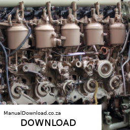
Replacing the planetary gear set on a Deutz 1011 F engine is a complex task that requires careful planning, appropriate tools, and a thorough understanding of the engine’s components. click here for more details on the download manual…..


    Deutz 2011 fuel control rod stuck, fixed the easy way..

    Deutz f4m 1011f engine not starting, priming injection pumps, timing belt In this video I go over what I have learned in last few weeks about this engine and how to figure out some of the problems with not …

Below is a detailed guide on how to perform this procedure, including descriptions of the components involved.

### Tools and Equipment Needed
1. **Basic hand tools**: Wrenches, sockets, screwdrivers, pliers, etc.
2. **Torque wrench**: For tightening bolts to the manufacturer’s specifications.
3. **Engine hoist or lifting equipment**: To safely lift the engine if necessary.
4. **Piston ring compressor**: If you need to remove pistons.
5. **Gasket scraper**: For cleaning surfaces.
6. **Clean rags and degreaser**: For cleaning parts.
7. **Sealant**: Manufacturer-recommended sealant for gaskets.
8. **Service manual**: For reference to specific torque specs and procedures.

### Components of the Planetary Gear Set
1. **Sun gear**: The central gear that drives the other gears in the planetary system.
2. **Planet gears**: Gears that rotate around the sun gear and are mounted on a carrier.
3. **Planet carrier**: The component that holds the planet gears and allows them to rotate.
4. **Ring gear**: The outer gear that encircles the planet gears and meshes with them.
5. **Output shaft**: The shaft that transfers power from the gear set to other components of the engine.
6. **Bearings and seals**: Used to support the rotating components and prevent leaks.

### Procedure for Planetary Gear Set Replacement

#### 1. Preparation
– **Safety First**: Ensure the engine is off, cool, and disconnected from any power source. Wear appropriate personal protective equipment (PPE).
– **Documentation**: Take photos or make notes of the assembly before disassembly to ensure accurate reassembly.

#### 2. Disassemble the Engine
– **Remove the Engine from the Chassis**: If the engine is part of a larger assembly, you may need to unbolt it from the chassis and use a hoist to lift it out.
– **Drain Fluids**: Remove the oil and coolant to prevent spills during disassembly.
– **Remove Components**:
– Remove any components that obstruct access to the planetary gear set, such as the oil pan, timing cover, or other auxiliary components.
– Unbolt the flywheel if it’s connected to the planetary gear set.

#### 3. Accessing the Planetary Gear Set
– **Locate the Gear Set**: Identify where the planetary gear set is located within the engine assembly.
– **Disassemble Surrounding Components**: Unbolt and remove any additional covers or components that house the planetary gear set.

#### 4. Removal of the Old Planetary Gear Set
– **Take Note of Orientation**: Pay attention to how the planetary gear set is installed, noting any specific orientations or markings.
– **Remove the Ring Gear**: Unbolt the ring gear from its housing. Care should be taken to avoid damaging any surrounding components.
– **Extract the Planet Carrier**: Carefully pull out the planet carrier, ensuring that the planet gears do not fall out.
– **Remove the Sun Gear**: Unbolt and remove the sun gear from its position.

#### 5. Inspect Components
– **Check for Wear**: Inspect all components for wear or damage. look for scoring on the gears, worn bearings, and seals that may need replacement.
– **Clean Components**: Use a degreaser to clean the components thoroughly, especially the surfaces where gaskets will be applied.

#### 6. Install New Planetary Gear Set
– **Install the Sun Gear**: Place the new sun gear in its original positiondownload Deutz 1011 F Engines workshop manual 
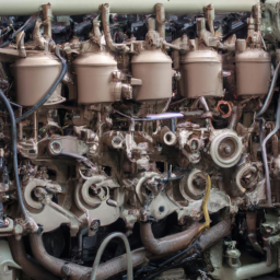
and bolt it in securely.
– **Place the Planet Carrier**: Install the planet carrier with the planet gears. Ensure they are seated correctly and rotate freely.
– **Install the Ring Gear**: Attach the ring gear to its housing, ensuring it meshes correctly with the planet gears.

#### 7. Reassemble the Engine
– **Replace any Gaskets or Seals**: Use new gaskets and seals to prevent leaks. Apply sealant as necessary according to the manufacturer’s specifications.
– **Reinstall the Components**: Reinstall any components that were removed, such as the oil pan and timing cover, in reverse order of disassembly.
– **Bolt Tightening**: Use a torque wrench to tighten bolts to the specified torque settings.

#### 8. Final Checks and Testing
– **Reinstall the Engine**: If the engine was removed from the chassis, carefully reinstall it and reconnect all components.
– **Refill Fluids**: Refill the engine with oil and coolant.
– **Start the Engine**: After reassembly, start the engine and listen for unusual noises. Check for leaks around the planetary gear set area.
– **Test Drive**: If applicable, take the vehicle for a test drive to ensure the gear set operates correctly under load.

### Conclusion
Replacing the planetary gear set on a Deutz 1011 F engine requires a meticulous approach to ensure proper installation and functionality. Always refer to the specific service manual for torque specifications and any specific procedures related to your engine model. If you are unsure about any step, consider consulting with or hiring a qualified mechanic.
The turn signal switch is a critical component of a vehicle’s lighting and signaling system, designed to enhance road safety by communicating a driver’s intentions to other road users. Located on the steering column or the steering wheel, this switch is easily accessible for the driver, allowing for quick activation while driving.

The primary function of the turn signal switch is to control the vehicle’s turn signals, which are flashing lights located at the front and rear of the vehicle. When a driver intends to make a turn or change lanes, they activate the switch, which sends an electrical signal to the turn signal lights, causing them to flash. This alerts other drivers and pedestrians of the driver’s intentions, thereby reducing the risk of accidents.

In addition to controlling turn signals, many turn signal switches also incorporate other functions, such as the hazard lights, which activate all four turn signals simultaneously to warn other drivers of a stationary or slow-moving vehicle. Some switches may also integrate features like high beam headlights and windshield wipers, offering convenience and multifunctionality.

Modern turn signal switches often include additional technological advancements, such as automatic cancellation mechanisms that deactivate the turn signals after the turn is completed. This feature is crucial in preventing drivers from forgetting to turn off the signal, which could mislead other road users. Overall, the turn signal switch is an essential safety feature that plays a significant role in effective vehicle operation and road safety.

Download DAIHATSU FEROZA ROCKY F300 COMPLETE Workshop Service Manual –

book shop
Certainly! click here for more details on the download manual…..


    Daihatsu feroza Australia f300 rugger sportrak rocky

    #daihatsu #feroza #4×4 #ferozagiant

Replacing the drive belt on a Daihatsu Feroza Rocky F300 can seem like a daunting task, but with a little patience and some basic tools, you can do it yourself. Here’s a step-by-step guide that breaks it down into simple terms:

### Tools and Materials Needed:
1. **New Drive Belt**: Make sure it’s the right size for your vehicle.
2. **Wrenches**: A set of wrenches to loosen bolts.
3. **Socket Set**: A socket wrench can make it easier to remove bolts.
4. **Screwdriver**: A flathead or Phillips screwdriver may be needed.
5. **Pliers**: For any stubborn clips or fasteners.
6. **Safety Gloves**: To protect your hands.
7. **Safety Glasses**: To protect your eyes from debris.

### Steps to Replace the Drive Belt:

#### 1. **Preparation**:
– **Park the Vehicle**: Make sure the vehicle is on a flat surface and parked safely.
– **Turn Off the Engine**: Ensure the engine is completely cool before starting.

#### 2. **Locate the Drive Belt**:
– Open the hood and locate the engine. The drive belt is usually found at the front of the engine and is a long rubber band that drives various components like the alternator, power steering pump, and sometimes the water pump.

#### 3. **Identify the Tensioner**:
– Look for the tensioner pulley, which keeps the belt tight. This is usually a small wheel Attached to a spring mechanism.

#### 4. **Release the Tension**:
– Use a wrench or a socket to turn the tensioner pulley. This will relieve tension on the belt, making it easier to remove. Hold it in place while you work.

#### 5. **Remove the Old Belt**:
– Carefully slide the old belt off the pulleys. Take Note of how the belt is routed around the pulleys, as you will need to install the new belt in the same way.

#### 6. **Install the New Belt**:
– Place the new belt over the pulleys, following the same routing as the old one. Ensure it sits properly in the grooves of each pulley.

#### 7. **Reapply Tension**:
– Once the belt is in place, slowly release the tensioner to apply tension to the new belt. Make sure the belt is tight but not overly stretched.

#### 8. **Check Alignment**:
– Spin the pulleys by hand to ensure the belt is aligned correctly and is running smoothly. It should not be rubbing against any other components.

#### 9. **Reassemble Everything**:
– If you had to remove any parts to access the belt, put them back in place and secure them with bolts or screws.

#### 10. **Test the Installation**:
– Start the enginedownload DAIHATSU FEROZA ROCKY F300 workshop manual and listen for any unusual noises. Check to make sure the belt is running smoothly without any wobbling.

### Tips:
– Always refer to the vehicle’s manual for specific details about the drive belt routing and specifications.
– If you’re unsure about any step, it’s okay to ask a friend for help or consult a professional mechanic.

### Safety Precautions:
– Always wear safety gloves and glasses while working on the engine.
– Ensure the engine is off and cool before starting.
– Be cautious of any moving parts when the engine is running.

By following these steps, you should be able to successfully replace the drive belt on your Daihatsu Feroza Rocky F300. Good luck!
Fog lights are specialized automotive lighting devices designed to improve visibility during adverse weather conditions, such as fog, rain, snow, or dust. Positioned lower on a vehicle, typically close to the ground, fog lights produce a wide, low beam of light that illuminates the road immediately in front of the car. This design helps reduce the amount of light that is reflected back into the driver’s eyes by fog, rain, or snow, which can happen with standard headlights.

Fog lights are usually mounted in pairs and can be found in various forms, including halogen, LED, or HID (High-Intensity Discharge) technologies. The light pattern produced by fog lights is designed to create a broad, horizontal beam that casts light onto the road surface, allowing the driver to see obstacles and lane markings more clearly without causing glare for oncoming traffic.

In addition to their practical function, fog lights can also enhance the aesthetic appeal of a vehicle, giving it a more aggressive or sporty appearance. Many modern cars come equipped with fog lights as standard or optional features, and they are typically activated separately from the main headlights. Proper use of fog lights is crucial; they should only be employed in conditions that warrant their use, as they can be blinding to other drivers when used in clear weather. Overall, fog lights are an essential safety feature that contributes to improved visibility and driving confidence in challenging conditions.

Download Jaguar XKR 1999 2000 2001 2002 2003 Workshop Service Manual –

stores
**Output Shaft Seal Replacement on a Jaguar XKR** – **Tools and Materials Needed:** – **Socket Set:** A comprehensive socket set, including metric sizes, for various bolts and nuts. click here for more details on the download manual…..


    Jaguar XK (X150) | Safety Inspection |Preventative Maintenance | Brakes |Suspension | Wheels | Pt… Preventative Maintenance and Safety Inspection of braking wheel and suspension components. Top tips.

    2007 Jaguar XK convertible jump start and battery replacement

**Output Shaft Seal Replacement on a Jaguar XKR**

– **Tools and Materials Needed:**
– **Socket Set:** A comprehensive socket set, including metric sizes, for various bolts and nuts.
– **Torque Wrench:** For tightening bolts to the manufacturer’s specifications, ensuring proper fit and function.
– **Pliers:** Needle-nose and regular pliers for gripping and pulling components.
– **Flathead and Phillips Screwdrivers:** For removing screws and prying components gently.
– **Seal Puller Tool:** A specialized tool designed to remove seals without damaging the surrounding components.
– **Seal Installer Tool:** To install the new seal evenly without causing damage.
– **Gasket Scraper:** To clean the area where the old seal was located, ensuring a clean surface for the new seal.
– **Shop Towels or Rags:** For cleaning and wiping off excess oil or debris.
– **Replacement Output Shaft Seal:** ensure you have the correct part for your specific Jaguar XKR model.
– **Lubricant or Engine Oil:** To lubricate the new seal for easier installation.

– **Safety Precautions:**
– **Work in a Well-Ventilated Area:** ensure good airflow to avoid inhaling fumes from any fluids.
– **Use Safety Glasses and Gloves:** Protect your eyes from flying debris and your hands from sharp edges or chemicals.

– **Preparation:**
– **Disconnect the Battery:** Remove the negative terminal to prevent any electrical issues while working on the vehicle.
– **Raise the Vehicle:** Use a hydraulic jack to lift the car safely and secure it with jack stands.
– **Remove the Wheels (if necessary):** Take off the wheels for better access to the output shaft area.

– **Accessing the Output Shaft Seal:**
– **Locate the Output Shaft:** Identify the output shaft, typically connected to the transmission and leading to the differential.
– **Remove Any Necessary Components:** Depending on the specific layout, you may need to remove the driveshaft or other components obstructing access to the output shaft seal.

– **Removing the Old Output Shaft Seal:**
– **Inspect the Area:** Look for any signs of wear or damage around the seal.
– **Use the Seal Puller Tool:** Gently insert the tool under the edge of the old seal and pry it out carefully. Avoid damaging the surrounding housing.
– **Clean the Area:** Use a gasket scraper to remove any debris or remnants of the old seal from the housing surface.

– **Installing the New Output Shaft Seal:**
– **Lubricate the New Seal:** Apply a thin layer of lubricant or engine oil to the outer edge of the new seal to help it slide in easily.
– **Position the Seal:** Align the new seal with the housing and ensure it is seated evenly.
– **Use the Seal Installer Tool:** Carefully press the seal into place, ensuring it is flush with the housing and not tilted.

– **Reassembling the Components:**
– **Reattach Any Removed Parts:** If you had to take off the driveshaft or other components, reinstall them securely.
– **Tighten Bolts to Specifications:** Use a torque wrench to ensure all bolts are tightened to the manufacturer’s recommended torque values.

– **Final Steps:**
– **Reinstall the Wheels (if removed):** Put the wheels back ondownload Jaguar XKR workshop manual and tighten the lug nuts properly.
– **Lower the Vehicle:** Carefully remove the jack stands and lower the car back to the ground.
– **Reconnect the Battery:** Reattach the negative battery terminal.

– **Testing:**
– **Start the Vehicle:** Run the engine and check for leaks around the new seal.
– **Test Drive:** Take the car for a short drive to ensure everything is functioning correctly and monitor for leaks.

– **Cleanup:**
– **Dispose of Old Seal and Debris Properly:** Follow local regulations for disposing of automotive waste.
– **Organize Tools:** Clean and store all tools used during the replacement process.

By following these detailed steps, you can effectively replace the output shaft seal on a Jaguar XKR. Always refer to the vehicle’s service manual for specific instructions and torque specifications related to your model.
The exhaust manifold is a crucial component of an internal combustion engine, responsible for collecting exhaust gases from multiple cylinders and directing them into the exhaust system. Typically made of cast iron or stainless steel, the manifold is designed to withstand high temperatures and corrosive gases produced during the combustion process.

The primary function of the exhaust manifold is to gather the exhaust gases that exit each cylinder and funnel them into a single pipe, known as the exhaust pipe. This process is essential for the efficient operation of the engine, as it helps maintain optimal pressure within the engine’s cylinder head. By ensuring the smooth flow of exhaust gases, the manifold contributes to improved engine performance, fuel efficiency, and reduced emissions.

Exhaust manifolds can come in different designs, including log manifolds, tubular manifolds, and equal-length manifolds. Log manifolds are simpler and often found in older engines, while tubular designs are popular in performance applications due to their ability to enhance exhaust flow and reduce back pressure. Equal-length manifolds offer uniform exhaust flow, which can lead to better performance, particularly in high-performance vehicles.

Over time, exhaust manifolds can suffer from wear and tear due to exposure to intense heat and corrosive substances. Cracks, leaks, or warping can occur, leading to performance issues and increased emissions. Regular maintenance and timely replacement of the exhaust manifold are essential to ensure the longevity and efficiency of the engine.

Download BMW 740i 740iL 1991Service Repair Manual –

diy
Repairing or replacing the shift drum in a BMW 740i or 740iL involves several steps. click here for more details on the download manual…..


    BMW 740i e38 4.4 V8 (286hp) Acceleration Sound BMW 740i e38.

    2000 BMW 740i Sport Muffler Delete Deleted the mufflers on my 2000 BMW 740i. Here’s how it went down!

Here’s a reverse order breakdown of the process:

### 7. Reassemble the Transmission
– Reinstall the transmission pan and secure it with bolts.
– Reattach the transmission cooler lines and electrical connectors.
– Ensure all components are properly connected and tightened.

### 6. Install the New Shift Drum
– Carefully position the new shift drum in place.
– Align it with the shift forks and ensure it moves freely.
– Secure it according to the manufacturer’s specifications.

### 5. Remove the Old Shift Drum
– Disconnect the shift linkage and any associated wiring.
– Remove any retaining clips or bolts holding the old shift drum in place.
– Gently take out the old drum, being cautious not to damage surrounding components.

### 4. Prepare the Transmission for Access
– Drain the transmission fluid using a pan to catch any spills.
– Remove the transmission pan by unscrewing the bolts and carefully lifting it off.
– Depending on the model year, you may need to remove the valve body or other components to access the shift drum.

### 3. Lift the Vehicle
– Park the BMW on a flat surface and engage the parking brake.
– Use a jack to lift the front of the vehicle and secure it on jack stands.

### 2. Gather the Necessary Tools and Parts
– Obtain a replacement shift drum, appropriate tools (socket set, wrenches, etc.), and transmission fluid.
– Have a clean workspace ready for the disassembly and reassembly process.

### 1. Safety Precautions
– Disconnect the battery to prevent any electrical shorts or issues during the repair.
– Wear safety gear such as gloves and goggles to protect yourself.

This reverse order provides an outline of the shift drum repair process for a BMW 740i/740iL. Always refer to a specific service manual for detailed instructionsdownload BMW 740i 740iL workshop manual and torque specifications tailored to your vehicle.
A battery insulator is a crucial component in automotive battery systems, primarily designed to enhance safety and performance by preventing electrical shorts and protecting the battery from environmental factors. Typically made from non-conductive materials like rubber, plastic, or foam, battery insulators serve several key functions.

First and foremost, they act as a barrier between the battery terminals and any conductive surfaces within the engine compartment. This is vital because a short circuit can lead to serious issues such as battery failure, overheating, or even fires. By insulating the battery terminals, these components help ensure that the electrical current flows only through designated paths, safeguarding both the battery and the vehicle’s electrical system.

In addition to electrical insulation, battery insulators also provide physical protection. Batteries can be subjected to vibrations, shocks, and extreme temperatures during vehicle operation. A well-designed insulator helps to cushion the battery, reducing the risk of damage from these stresses. Moreover, it can help to minimize corrosion by keeping moisture and contaminants away from the battery terminals.

Furthermore, battery insulators can contribute to thermal management. By reducing heat transfer, they can help maintain optimal operating temperatures for the battery, thereby extending its lifespan and improving performance. Overall, the battery insulator plays a vital role in enhancing the reliability and longevity of a vehicle’s battery system, underscoring its importance in modern automotive design.

Download Dodge Ram 2500 Series 2002-2004 Workshop Service Manual –

service
### Strut Mount Replacement on a Dodge Ram 2500 #### Tools and Materials Needed – **Jack and Jack Stands** – A hydraulic floor jack to lift the vehicle safely. click here for more details on the download manual…..


    RAM 2500 Cummins DIESEL vs GAS (6.4 Hemi) | Which Engine Should you Buy? *Diesel Mechanic Explain… I discuss whether a Diesel Engine (6.7 Cummins) or a Gas Engine (6.4 Hemi) is the better choice for you to buy in your pick up …

    RAM 2500 Cummins 6.7L Diesel Engine ** Heavy Mechanic Review** | TOP 3 ISSUES I reviewed a 2023 RAM 2500 Cummins 6.7 Diesel Engine as a heavy duty mechanic. I talk about potential engine issues and …

### Strut Mount Replacement on a Dodge Ram 2500

#### Tools and Materials Needed
– **Jack and Jack Stands**
– A hydraulic floor jack to lift the vehicle safely.
– Jack stands to securely support the vehicle once lifted, ensuring safety during the process.

– **Lug Wrench**
– Used to loosen and remove the lug nuts on the wheels. A cross-pattern wrench or a breaker bar may be helpful for stubborn nuts.

– **Socket Set**
– A metric socket set (typically 10mm to 21mm) for various bolts on the strut assembly. A ratchet and extension will ease access in tight spaces.

– **Torque Wrench**
– Essential for ensuring that all bolts are tightened to the manufacturer’s specifications to avoid any issues after installation.

– **Pry Bar**
– Useful for separating components that might be stuck together, especially under tension.

– **Spring Compressor**
– A tool designed to safely compress the coil spring on the strut assembly, allowing for safe removal and installation. Ensure to follow the manufacturer’s instructions for safe operation.

– **Strut Mounts**
– Replacement strut mounts specific to the Dodge Ram 2500. It’s advisable to purchase high-quality mounts to maintain performance and longevity.

– **Grease or Lubricant**
– To apply on the mounts and bolts for ease of installation and to prevent rust.

– **Safety Gear**
– Safety glasses and gloves to protect yourself from debris and sharp edges.

#### Procedure for Strut Mount Replacement

– **Preparation**
– Park the vehicle on a flat, stable surface. engage the parking brake to prevent movement.

– **Lift the Vehicle**
– Use the jack to lift the front of the vehicle, then place jack stands under the frame to secure it. Ensure the vehicle is stable before proceeding.

– **Remove the Wheel**
– Use the lug wrench to loosen and remove the lug nuts, then take off the wheel to access the strut assembly.

– **Access the Strut Assembly**
– Locate the top and bottom bolts of the strut. The top bolts are typically found under the hood, while the bottom bolts are connected to the lower control arm.

– **Remove the Lower Strut Bolt**
– Use the appropriate socket to remove the lower bolt first. You may need to use a pry bar to help separate the strut from the control arm if it’s stuck.

– **Compress the Coil Spring**
– Carefully place the spring compressors on the coil spring. Ensure they are evenly spaced and tightened according to the compressor’s instructions. This ensures the spring is compressed safely while working on the strut mount.

– **Remove the Upper Strut Mount Bolts**
– Open the hood and locate the top strut mount. Remove the retaining nuts using the socket set, and be cautious as the spring may push the strut upwards once released.

– **Remove the Strut Assembly**
– Once the upper bolts are removed, gently lower the strut assembly from the vehicle. Ensure that the spring is still securely compressed.

– **Replace the Strut Mount**
– Remove the old strut mount from the strut assembly. Clean any debris from the mounting area. Install the new strut mount by aligning it properlydownload Dodge Ram 2500 workshop manual and securing it with the bolts.

– **Reassemble the Strut Assembly**
– Carefully raise the strut assembly back into position. Ensure that the new mount aligns with the holes in the body of the vehicle.

– **Tighten the Upper Bolts**
– Reinstall and tighten the upper strut mount bolts. Follow the manufacturer’s torque specifications closely.

– **Reinstall the Lower Strut Bolt**
– Position the strut into the lower control arm and insert the lower strut bolt, tightening it securely.

– **Remove the Spring Compressor**
– Once everything is secure, carefully remove the spring compressors, ensuring the strut and coil spring are stable.

– **Reinstall the Wheel**
– Place the wheel back onto the hub and hand-tighten the lug nuts. Lower the vehicle back to the ground and then use the torque wrench to tighten the lug nuts to the manufacturer’s specifications.

– **Final Checks**
– Before taking the vehicle for a test drive, double-check all fasteners, ensuring everything is secure. Take a moment to inspect the area for any tools or debris left behind.

– **Test Drive**
– Conduct a short test drive to ensure that everything feels normal and the new strut mounts are functioning correctly.

#### Safety Note
– Always exercise caution when working under a vehicle, and ensure your tools and equipment are in good condition to prevent accidents.
The fuel cap, often referred to as a gas cap, is a critical component of a vehicle’s fuel system. Its primary function is to seal the fuel tank, preventing fuel vapors from escaping into the atmosphere and protecting the tank’s contents from contaminants. Typically made from durable materials such as plastic or metal, the fuel cap is designed to withstand harsh environmental conditions, including extreme temperatures and exposure to fuel.

Fuel caps come in different designs, including screw-on caps, locking caps, and quick-release caps, each serving specific needs. Screw-on caps, which are most common, require the user to twist them to secure or release them from the fuel filler neck. Locking caps provide added security against fuel theft and tampering, while quick-release caps allow for faster refueling, often found in racing applications.

In addition to its sealing function, the fuel cap plays a crucial role in maintaining the vehicle’s fuel system pressure. A properly functioning cap ensures that the tank remains pressurized, which is essential for optimal fuel delivery to the engine. A malfunctioning or loose fuel cap can trigger warning lights on the dashboard and lead to reduced fuel efficiency, increased emissions, and potential engine performance issues. Therefore, regular inspection and maintenance of the fuel cap are vital for the overall health of a vehicle’s fuel system.

Download MAZDA RX7 COMPLETE Workshop Repair Manual 1992-1993 –

bookstore
Replacing the input shaft on a Mazda RX-7 is a complex process that requires a good understanding of automotive mechanics. click here for more details on the download manual…..


    Buying a 6 Speed Sequential Transmission for the 4 Rotor RX7 Showing the new sequential transmission, and game plan for the next few weeks. Ready to rock and roll high boost big power.

    Testing Premium Oil Filter for Mazda RX-7 The Mazda RX7’s rotary engine is nothing short of a cult classic thanks to its unmistakable sound and power to match.

Below is a step-by-step guide presented in reverse order, detailing how to complete this task:

### 10. Reassemble the Transmission
– **Reinstall the Transmission**: Carefully raise the transmission back into position with the help of a jack or an assistant.
– **Reconnect the Shift Linkage**: Reattach the shift linkage and ensure it is functioning correctly.
– **Reattach the Transmission Mounts**: Secure the transmission to the chassis using the transmission mounts.

### 9. Reinstall the Driveshaft
– **Reconnect the Driveshaft**: Align the driveshaft with the transmission output and secure it in place.
– **Tighten Bolts**: Ensure all bolts are tightened to the manufacturer’s torque specifications.

### 8. Fill Transmission with Fluid
– **Add Transmission Fluid**: Fill the transmission with the appropriate type and amount of fluid through the fill port, following the specifications in your service manual.

### 7. Install the Clutch
– **Align the Clutch Disc**: Position the new clutch disc onto the flywheel and ensure it is correctly aligned using a clutch alignment tool.
– **Attach the Pressure Plate**: Secure the pressure plate to the flywheel, tightening the bolts in a crisscross pattern to ensure even pressure.

### 6. Remove the Old Input Shaft
– **Extract Input Shaft**: Slide the old input shaft out of the transmission case. You may need to pull it gently if it is stuck.
– **Inspect Components**: Check the condition of the input bearing and other related components for wear or damage.

### 5. Prepare for Input Shaft Replacement
– **Remove the Transmission**: Disconnect all necessary components (electrical connectors, speedometer cable, etc.) and unbolt the transmission from the engine.
– **Use a Transmission Jack**: Safely lower the transmission from the vehicle.

### 4. Access the Input Shaft
– **Remove the Bell Housing**: unscrew the bell housing from the transmission to access the input shaft.
– **Detach Other Components**: You may need to remove other components like the clutch and flywheel to reach the input shaft.

### 3. Gather Tools and Supplies
– **Tools Needed**: Collect tools such as wrenches, sockets, screwdrivers, a jack, and a clutch alignment tool.
– **Replacement Parts**: Obtain a new input shaft, clutch kit, and any seals or bearings necessary for the installation.

### 2. Prepare the Vehicle
– **Lift the Vehicle**: Secure the vehicle on jack sdownload MAZDA RX7 workshop manualtands to provide safe access to the underside.
– **Disconnect the Battery**: Ensure safety by disconnecting the negative terminal of the battery.

### 1. Review the Service Manual
– **Consult the Manual**: Before starting, review the specific service manual for your Mazda RX-7 to understand the detailed steps and torque specifications.

By following these steps in reverse order, you can successfully replace the input shaft on a Mazda RX-7. Always ensure safety precautions are taken, and if you are uncertain at any point, consider consulting a professional mechanic.
A tail light is an essential component of a vehicle’s lighting system, primarily designed to enhance safety and visibility on the road. Located at the rear of the vehicle, tail lights serve multiple functions, including signaling the vehicle’s presence to drivers behind it, indicating when the vehicle is braking, and providing information about the vehicle’s direction through turn signals.

Typically, tail lights consist of several different bulbs, each serving a specific purpose. The main red light serves as the standard tail light, illuminating when the vehicle’s headlights are activated, thereby making the car more visible to other road users in low-light conditions. When the driver applies the brakes, a brighter red light activates to signal to other drivers that the vehicle is slowing down or stopping. Additionally, amber or yellow lights are commonly used for turn signals, flashing to indicate the direction of a turn or lane change.

Modern tail lights often incorporate advanced technologies such as LED lighting, which offers greater energy efficiency, longer lifespan, and quicker response times compared to traditional incandescent bulbs. Moreover, many vehicles now feature design elements like sequential turn signals or dynamic lighting patterns that enhance aesthetic appeal and further improve visibility. Overall, tail lights play a crucial role in road safety, communication between drivers, and the overall functionality of a vehicle.

Download 2005 Renault Thalia Service and Repair Manual –

get
Replacing the transmission filter in a Renault Thalia can be a bit complex, especially if you have limited mechanical experience. click here for more details on the download manual…..


    2019 Renault Clio Salvage Repair In 1 Video! Music: White Flower by tubebackr is licensed under a Creative Commons License. https://creativecommons.org/licenses/…

    2009 Renault Thalia 1.6 Automatic Features Body Type: 4 doors / 5 seats Weight:1000 Kg Length:4261 mm Height:1439 mm Wheelbase:2473 mm Engine location:front Fuel …

However, I’ll break it down into simple steps. It’s important to note that if you’re unsure about any part of the process, it might be best to consult a professional mechanic. Here’s a basic guide:

### Tools and Materials Needed:
1. **New Transmission Filter**: Make sure it’s compatible with your Renault Thalia.
2. **Transmission Fluid**: This is usually needed after replacing the filter.
3. **Socket Set**: To remove bolts.
4. **Screwdriver Set**: To remove any clips or screws.
5. **Oil Drain Pan**: To catch old fluid.
6. **Rags or Towels**: For cleaning up spills.
7. **Jack and Jack Stands**: To lift the car safely.
8. **Safety Goggles and Gloves**: To protect yourself.

### Steps to Replace the Transmission Filter:

1. **Prepare the Vehicle**:
– Park your Renault Thalia on a flat surface.
– Engage the parking brake.
– To ensure safety, use a jack to lift the front of the car and place jack stands underneath.

2. **Locate the Transmission Pan**:
– Get under the vehicle and locate the transmission pan. This is usually a large metal pan located under the vehicle, where the transmission fluid is stored.

3. **Drain the Transmission Fluid**:
– Place the oil drain pan under the transmission pan.
– Carefully remove the bolts holding the transmission pan in place (some may be difficult to reach). Be prepared for some fluid to spill out.
– Once the fluid has drained, remove the transmission pan completely.

4. **Remove the Old Filter**:
– The transmission filter is typically located inside or near the transmission pan.
– Disconnect any clips or bolts holding the filter in place.
– Gently pull out the old filter. Be careful, as it may still have fluid in it.

5. **Install the New Transmission Filter**:
– Take your new transmission filter and insert it into the same position as the old one.
– Secure it with any clips or bolts that were holding the old filter in place.

6. **Clean and Reattach the Transmission Pan**:
– Before reattaching the transmission pan, clean the surface where it meets the transmission. This helps ensure a good seal.
– If there’s a gasket, check if it needs replacement. If it’s damaged, replace it.
– Reattach the transmission pan and tighten the bolts securely.

7. **Add New Transmission Fluid**:
– Locate the transmission dipstick (usually marked with a unique color).
– Using a funnel, pour the new transmission fluid into the dipstick tube. Refer to your owner’s manual for the correct type and amount of fluid needed.

8. **Check the Fluid Level**:
– Start the Engine and let it run for a few minutes. Shift through the gears to circulate the fluid.
– With the Engine running, check the fluid level using the dipstick. Add more fluid if necessary.

9. **Check for Leaks**:
– After everything is back together, check under the car for any leaks while the Engine is running.

10. **Lower the Vehicle**:
– Once you’re sure there are no leaks, carefully lower the vehicle back to the ground.

### Final Tips:
– Always refer to your vehicle’s manual for specific details related to your model.
– If you are unsure about any step, don’t hesitate to reach out to a professional mechanic for assistance.
– It’s a good practice to change the transmission filterdownload Renault Thalia workshop manual and fluid regularly to keep your car in good condition.

By following these steps, you should be able to successfully replace the transmission filter in your Renault Thalia. Good luck!
A heater hose is a vital component of a vehicle’s heating system, responsible for transporting coolant between the Engine and the heater core. The heater core acts as a mini-radiator located inside the cabin of the vehicle, allowing hot coolant to flow through it and transfer heat to the air that is blown into the passenger compartment by the car’s heating system. The heater hose facilitates this process by carrying the coolant from the engine, where it is heated, to the heater core, and then returning cooler coolant back to the engine.

Typically made from durable rubber or silicone, heater hoses are designed to withstand high temperatures and pressures, as they are directly involved in the engine’s cooling system. Over time, exposure to heat, pressure, and the harsh chemicals in the coolant can lead to wear and tear on the hoses, resulting in cracks, leaks, or even complete failure. Regular inspection of heater hoses is crucial for maintaining the efficiency of the heating system and preventing potential overheating of the engine.

In colder climates, a malfunctioning heater hose can lead to inadequate heating of the cabin, making driving uncomfortable during winter months. Additionally, leaks in the heater hose can lead to coolant loss, which can compromise the entire cooling system, leading to Engine overheating and potential damage. Therefore, ensuring the integrity of the heater hose is essential for both comfort and Engine health.

Download Hyundai R55-3 Crawler Excavator Service Repair Workshop Manual –

repair
Replacing the water pump on a Hyundai R55-3 Crawler Excavator involves several steps and tools. click here for more details on the download manual…..


    1999 Hyundai Robex R55-3 Excavator – Lot 11336

    Travel gearbox reduction delivery Travel gearbox reduction delivery.

Below is a detailed guide to help you through the process:

– **Safety Precautions**
– Ensure the excavator is parked on a flat, stable surface.
– Engage the parking brake and turn off the engine.
– Disconnect the battery to prevent any electrical issues or accidental starting.

– **Tools Required**
– **Socket Set**: A complete set of sockets (metric) will be necessary for removing bolts and nuts.
– **Wrenches**: Adjustable and fixed wrenches for accessing hard-to-reach areas.
– **Screwdrivers**: Both flathead and Phillips for removing any covers or clamps.
– **Pliers**: For gripping hoses and clamps.
– **Torque Wrench**: To ensure bolts are tightened to the manufacturer’s specifications.
– **Pry Bar**: Useful for gently loosening components if they are stuck.
– **Oil Catch Pan**: To collect any coolant that might spill during the replacement.
– **Clean Rags**: For cleaning surfaces and wiping up spills.
– **Gasket Scraper**: To remove old gaskets from the water pump mounting surface.
– **New water Pump**: Ensure you have the correct replacement part for your specific model.
– **Sealant (if needed)**: Depending on the design, a gasket sealant may be required for the new pump.

– **Preparation**
– Allow the engine to cool completely to avoid burns from hot coolant.
– Place the oil catch pan under the water pump to catch any coolant that may leak out.
– Remove any covers or panels obstructing access to the water pump.

– **Drain Coolant**
– Locate the coolant drain plug on the radiator or engine block.
– Open the drain plug and allow the coolant to fully drain into the oil catch pan.
– Replace the drain plug once the coolant has finished draining.

– **Remove the Old water Pump**
– Disconnect any hoses attached to the water pump. Use pliers to loosen hose clamps if necessary.
– Remove any brackets or components that may obstruct access to the water pump.
– Unscrew the bolts securing the water pump to the engine. Keep track of their locations, as they may vary in length.
– Carefully pull the water pump off the engine. If it is stuck, gently use a pry bar to loosen it without damaging the mounting surface.

– **Clean the Mounting Surface**
– Use the gasket scraper to remove any remnants of the old gasket from the mounting surface on the engine.
– Clean the area thoroughly to ensure a good seal for the new water pump.

– **Install the New water Pump**
– Position the new water pump onto the engine, aligning it with the bolt holes.
– If required, apply gasket sealant or place a new gasket onto the mounting surface.
– Insertdownload Hyundai R55 3 Crawler Excavator workshop manual and hand-tighten the bolts to hold the pump in place, then use a torque wrench to tighten them to the manufacturer’s specifications.

– **Reconnect Hoses and Components**
– Reattach all hoses to the new water pump, ensuring that hose clamps are securely fastened.
– Reinstall any brackets or components that were removed earlier.

– **Refill Coolant**
– Fill the coolant system with the appropriate coolant mixture. Refer to the owner’s manual for the correct type and mixture ratio.
– Start the engine and let it run for a few minutes while checking for leaks around the new water pump.

– **Check for Proper Operation**
– Monitor the temperature gauge to ensure the engine is not overheating.
– After the engine has run for a while, check the coolant level and top off if necessary.

– **Final Steps**
– Reconnect the battery.
– Replace any covers or panels that were removed.
– Dispose of the old coolant and any waste material properly, following local regulations.

By following these steps, you should be able to successfully replace the water pump on your Hyundai R55-3 Crawler Excavator. Always refer to the specific service manual for your machine for any additional details or specifications related to your model.
An expansion tank, often referred to as a coolant reservoir or overflow tank, is a crucial component of a vehicle’s cooling system. Its primary function is to manage the coolant that circulates through the engine to maintain optimal operating temperatures. As the engine heats up during operation, the coolant expands due to thermal expansion. The expansion tank provides a designated space for this excess coolant, preventing pressure build-up in the cooling system, which could lead to potential damage or leaks.

Typically made from plastic or metal, the expansion tank is connected to the radiator and the engine via hoses. It features a cap that is designed to release pressure when it exceeds a certain threshold, allowing excess coolant to flow into the tank. When the engine cools down, the coolant contracts and creates a vacuum, which draws the coolant back into the system, ensuring that the cooling system remains properly filled.

In addition to its primary function, the expansion tank often serves as a sight gauge, allowing drivers to easily check the coolant level without needing to open the radiator cap, which can be dangerous due to high pressure and temperature. Regular inspection of the expansion tank is essential, as any cracks or leaks can lead to coolant loss, overheating, and ultimately, engine failure. Overall, the expansion tank plays a vital role in maintaining engine efficiency and longevity.

Download Case 504BD, 504BDT PartsService Manual –

do your own repairs
Repairing a differential gear on a Case 504BD or 504BDT involves several steps. click here for more details on the download manual…..


    2013 Mercedes Benz G Class – G 63 AMG WDCYC7DF2DX210284 Although every reasonable effort has been made to ensure the accuracy of the information contained in …

    Case® 504BDT Runner | CS504TCE2-2336719 Case® 504BDT Runner Turbocharged Diesel Block C/N: A66526 Head C/N: A156738.

Here’s a reverse order guide for the repair process, starting from the final steps to the initial preparations:

### 10. Reassembly
– **Install Differential Cover**: Place the differential cover back on, ensuring all gaskets and seals are properly seated to prevent leaks.
– **Torque Fasteners**: Tighten the cover bolts to the manufacturer’s specifications using a torque wrench.
– **Reinstall Axle Shafts**: Slide the axle shafts back into place, ensuring they are properly seated.
– **Install Wheel Hubs**: Reattach the wheel hubs, ensuring that all bolts are torqued to specifications.

### 9. Final Adjustments
– **Check Fluid Levels**: Refill the differential with the appropriate gear oil, checking the level according to the specifications.
– **Inspect for Leaks**: After everything is reassembled, run the vehicle briefly and check for any leaks around the differential.

### 8. Testing
– **Test Drive**: Take the vehicle for a short drive to ensure the differential operates correctly without any unusual noises or issues.
– **Listen for Noise**: Pay attention to any abnormal sounds that could indicate improper installation or issues with the gears.

### 7. Cleaning
– **Clean Surfaces**: Clean any remaining surfaces of the differential housing and cover to remove old gasket material and dirt.
– **Inspect Components**: Check all parts for wear, damage, or misalignment. Replace any worn or damaged components as necessary.

### 6. Inspection and Replacement
– **Remove Old Gears**: Carefully take out the old differential gears, paying attention to how they are arranged.
– **Inspect Bearings**: Check the differential bearings and races for wear. Replace them if necessary.
– **Install New Gears**: If applicable, install new differential gears, ensuring proper alignment and fitting.

### 5. Disassembly
– **Remove Differential Housing**: Unbolt and remove the differential housing from the axle or transmission.
– **Drain Oil**: Drain the differential oil to prevent spills during disassembly.

### 4. Preparation
– **Gather Tools**: Collect necessary tools, including wrenches, a torque wrench, socket set, clean rags, and replacement parts.
– **Safety Precautions**: Ensure the vehicle is on a flat surface, secured with wheel chocks, and that you have the necessary safety gear.

### 3. Reference Manual
– **Consult Service Manual**: Before starting, refer to the Case 504BD or 504BDT service manual for specific procedures, torque specifications, and any special notes related to your model.

### 2. Diagnosis
– **Identify the Issue**: Determine the specific problem with the differential, such as noise, loss of power, or leaks.

### 1. Preparation of Work Area
– **Create a Safe Workspace**: Ensure your work area is clean, organized,download Case 504BD 504BDT workshop manual and well-lit. remove any obstacles that could create hazards.

By following these steps in reverse order, you can effectively conduct differential gear repair on a Case 504BD or 504BDT. Always refer to the manufacturer’s service manual for detailed instructions and specifications relevant to your specific model.
The engine bay, often referred to as the engine compartment, is a crucial area within a vehicle where the engine and its associated components are housed. Located at the front of the vehicle in most cars, the engine bay is designed to provide a protective environment for the engine while allowing for efficient operation and maintenance.

Typically, the engine bay contains not only the engine itself but also several key components such as the radiator, battery, air intake system, and various hoses and wiring harnesses. This area is engineered to facilitate the cooling of the engine, with the radiator and cooling fans working to dissipate heat generated during combustion. The design of the engine bay also aims to minimize noise and vibration, ensuring a smoother ride for occupants.

Accessing the engine bay is generally straightforward, with a hood that can be opened for maintenance and repairs. This allows mechanics and car owners to perform routine checks and services, such as oil changes, replacing filters, or inspecting belts and hoses. The layout of the engine bay can vary significantly between different makes and models of vehicles, with some designed for compactness and others for ease of access to components.

Overall, the engine bay is a vital aspect of automotive design, playing a significant role in the vehicle’s performance, reliability, and serviceability. Its configuration can greatly influence the ease with which maintenance tasks can be performed, as well as the overall efficiency of the engine itself.

Download 1991 Mercedes-Benz G-Class G290GD (W460/W461) OEM Download Service & Repair Manual Software –

book store
Replacing a serpentine belt on a Mercedes-Benz G-Class G290GD (W460/W461) can be done with some basic tools and a little patience. click here for more details on the download manual…..


    2013 Mercedes Benz G Class – G 63 AMG WDCYC7DF2DX210284 Although every reasonable effort has been made to ensure the accuracy of the information contained in …

Here’s a step-by-step guide to help you through the process:

### Tools and Materials Needed:
– New serpentine belt (make sure it’s the right size for your model)
– Socket wrench set
– Ratchet and socket (typically 10mm or 13mm)
– A belt tensioner tool (or a long wrench)
– Pliers (optional)
– A flashlight (for better visibility)
– Safety gloves and goggles (for protection)

### Step-by-Step Instructions:

1. **Safety First**:
– Park the vehicle on a flat surface and turn off the engine.
– Engage the parking brake to prevent any movement.
– If the engine is hot, allow it to cool down before starting.

2. **Locate the Serpentine Belt**:
– Open the hood and locate the serpentine belt. It’s a long rubber belt that wraps around several pulleys, including the alternator, power steering pump, and air conditioning compressor.

3. **Check the Belt Routing**:
– Before removing the belt, take a picture of how it’s routed around the pulleys. this will help you install the new belt correctly.

4. **Release Tension on the Belt**:
– Locate the belt tensioner, which is a spring-loaded pulley that keeps the belt tight. Use a belt tensioner tool or a long wrench to rotate the tensioner in the direction indicated (usually clockwise or counterclockwise). this will relieve tension on the belt.
– While holding the tensioner, slide the belt off one of the pulleys (ideally the easiest one to access).

5. **Remove the old Belt**:
– Once the tension is released and the belt is off a pulley, carefully remove the belt from the remaining pulleys.

6. **Compare the New Belt**:
– Take the new serpentine belt and compare it to the old one to ensure they are the same length and width.

7. **Install the New Belt**:
– Refer to the picture you took earlier and start routing the new belt around the pulleys. Make sure it sits in the grooves of each pulley correctly.
– Once you have the belt in place, it’s time to reapply tension. Again, use the tensioner tool to rotate the tensioner and slip the belt over the last pulley.

8. **Check the Installation**:
– After the belt is installed, double-check that it’s properly seated on all pulleys. It should not be twisted or misaligned.

9. **Test the Tension**:
– Release the tensioner slowly and ensure that the belt is tight and secure. You should not be able to easily pull it off the pulleys.

10. **Final Check**:
– Make sure all tools are removed from the engine bay.
– Close the hooddownload Mercedes Benz G Class G290GD W460 W461 OEM workshop manual and start the engine. Listen for any unusual noises. The belt should run smoothly without slipping or squeaking.

11. **Dispose of the old Belt**:
– Dispose of the old serpentine belt responsibly.

### Tips:
– If you’re unsure about any step, consult the vehicle’s owner manual or a repair guide specific to the G-Class.
– If you encounter any difficulties, don’t hesitate to ask a more experienced friend or a professional for help.

By following these steps, you should be able to replace the serpentine belt on your Mercedes-Benz G-Class successfully!
Cruise control is an electronic system in vehicles designed to automatically control the speed of the car, allowing for a more relaxed driving experience, particularly during long highway journeys. this system enables the driver to set a desired speed, which the vehicle will maintain without the need for the driver to continuously press the accelerator pedal. this is especially useful for maintaining a steady speed on long stretches of road, thereby reducing fatigue and improving fuel efficiency.

The basic components of cruise control include a speed sensor, an actuator, and a control module. when a driver activates cruise control, the system takes over the throttle control of the vehicle. The speed sensor monitors the current speed of the car, while the actuator adjusts the throttle position to maintain the set speed, compensating for changes in road incline and other factors.

Modern vehicles often come equipped with advanced features such as adaptive cruise control (ACC), which uses radar and cameras to monitor traffic conditions. this allows the system to automatically adjust the vehicle’s speed to maintain a safe following distance from the car ahead, enhancing safety and convenience. Some high-end systems even include stop-and-go functionality, enabling the vehicle to come to a complete stop and resume speed in heavy traffic.

Overall, cruise control is an essential component that enhances driving comfort, efficiency, and safety, making it a popular feature in contemporary automobiles.