Download Jeep CJ-3A 1949-1953 Workshop Service Manual –

fix
Replacing a CV joint on a Jeep CJ-3A involves several steps to ensure that you perform the repair safely and effectively. click here for more details on the download manual…..


    1949 CJ-3A – L134 – Flathead – Freeze / Core Plug Replacement & Cooling System Flush Welcome back to channel! In today’s video, I cover replacing a common freeze plug on the L134 flathead in this ’49 CJ-3A. *If you …

    Comparison of Jeep CJ3A & M38 Walk-Around and Comparison of CJ3A & M38 Jeep Willy’s with ​⁠@therealjeepguy #jeep #thejeepguy #offroad #willysjeep …

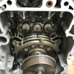
The CV (constant velocity) joint is a crucial component that allows the drive shaft to transmit power to the wheels while accommodating the up-and-down motion of the suspension and allowing for steering. Here’s a detailed guide on how to perform a CV joint replacement:

### Tools and Materials Needed:

1. **Tools:**
– Socket set (including deep sockets)
– Wrench set
– Torque wrench
– Pliers
– Screwdrivers (flathead and Phillips)
– Hammer
– Pry bar
– Jack and jack stands
– CV joint puller (if necessary)

2. **Materials:**
– Replacement CV joint or axle assembly
– New CV joint grease (if applicable)
– New axle nut (if applicable)
– New cotter pins (if applicable)
– Brake cleaner
shop rags or paper towels

### Step-by-Step Guide:

#### 1. Preparation:
– **Safety First:** Park the Jeep on a flat surface, engage the parking brake, and place wheel chocks behind the rear wheels.
– **Gather Tools and Materials:** Ensure you have all the necessary tools and replacement parts before starting.

#### 2. Lift the Jeep:
– Use a jack to lift the front of the Jeep CJ-3A and secure it on jack stands. Make sure it’s stable before proceeding.

#### 3. Remove the Wheel:
– **Loosen Lug Nuts:** Using a socket wrench, slightly loosen the lug nuts on the front wheel where you are replacing the CV joint.
– **Remove Wheel:** Completely remove the lug nuts and take off the wheel.

#### 4. Remove the Brake Caliper (if applicable):
– Depending on your Jeep’s setup, you might need to remove the brake caliper to access the CV joint. If so:
– Remove the bolts holding the caliper in place.
– Carefully hang the caliper using Wire or a bungee cord to prevent stress on the brake line. Do not let it hang by the brake line.

#### 5. Remove the Axle Nut:
– **Access the Axle Nut:** If there’s a dust cover, remove it to access the axle nut.
– **Remove the Nut:** Use a socket wrench to remove the axle nut. If it’s stubborn, a breaker bar may be necessary.

#### 6. Detach the CV Joint from the Wheel Hub:
– **Pry Out the CV Joint:** Use a pry bar to carefully separate the CV joint from the wheel hub. Be cautious not to damage any surrounding components.
– If the joint is stuck, you may need to tap it gently with a hammer, But be careful to avoid damaging the threads or the hub.

#### 7. Remove the CV Joint from the Differential:
– **Access the CV Joint:** If the CV joint connects to the differential, you will need to pull it out.
– **Pull the Joint Out:** Gently pull the CV axle out of the differential. You may need to rotate the axle slightly to ease the removal.

#### 8. compare Old and New CV Joint:
– Before installation, compare the old CV joint with the new one to ensure they are the same size and fit.

#### 9. Install the New CV Joint:
– **Insert the New Joint:** Slide the new CV joint into the differential first. Ensure it is seated properly.
– **Reattach to Wheel Hub:** Align the CV joint with the wheel hub and push it into place. You may need to rotate it slightly to get it fully seated.

#### 10. Replace the Axle Nut:
– Once the CV joint is in place, thread on the new axle nut. Make sure it’s download Jeep CJ 3A workshop manualhand-tightened first.

#### 11. Reinstall the Brake Caliper (if removed):
– Reattach the brake caliper and tighten the bolts securely.

#### 12. Replace the Wheel:
– **Reattach the Wheel:** place the wheel back on and hand-tighten the lug nuts.
lower the Jeep back to the ground.

#### 13. Tighten the Axle Nut and Lug Nuts:
– **Torque the Axle Nut:** Use a torque wrench to tighten the axle nut to the manufacturer’s specifications.
– **Torque the Lug Nuts:** Tighten the lug nuts in a crisscross pattern to ensure even pressure.

#### 14. Test the Repair:
– Before taking the Jeep for a drive, check that everything is secure and properly installed. Test drive the vehicle at low speed to listen for any unusual noises.

### Final Thoughts:
Replacing a CV joint can be a challenging task, especially for those unfamiliar with automotive repairs. If you’re unsure or uncomfortable with any step, consider consulting a professional mechanic. Always refer to the Jeep CJ-3A’s repair manual for specific torque specifications and detailed diagrams for your particular model.
An odometer is a vital instrument found in vehicles that measures the distance traveled by the vehicle over its lifespan. It is an essential component for both drivers and automotive professionals, as it provides crucial information regarding the vehicle’s usage and helps in assessing its overall condition. Traditionally, odometers were mechanical devices consisting of a series of gears and rotating drums that displayed the mileage on a physical dial. However, modern vehicles typically use electronic odometers, which display the distance digitally on the dashboard.

Odometers serve several important functions. For one, they help vehicle owners monitor maintenance schedules; many maintenance tasks are recommended based on mileage, such as oil changes, tire rotations, and other critical services. Furthermore, the odometer reading is a key factor in determining the vehicle’s resale value. A car with lower mileage is often perceived as being in better condition and may command a higher price in the used car market.

In addition to standard distance measurement, some odometers also include trip settings that allow drivers to track the distance of specific journeys separately from the total mileage. This feature can be useful for calculating fuel efficiency or for business purposes, where mileage tracking is essential for expense reimbursement.

Lastly, it is important to note that tampering with odometers, a practice known as “odometer rollback,” is illegal in many jurisdictions, as it misrepresents the vehicle’s true usage and can lead to significant financial and safety implications for future buyers. Overall, the odometer is a fundamental component that plays a crucial role in vehicle maintenance, valuation, and safety.

Download MAZDA 3Service & Repair Manual 2003-2006 –

stores
Repairing power steering on a Mazda 3 can be a bit complex, but I’ll break it down into simpler steps. click here for more details on the download manual…..


    2024 Mazda3 vs Mazda CX-30 / Open and Shut? On the surface, the CX-30 is a more versatile, AWD Mazda3 without a real price increase. After driving them back to back, the …

    How to fix heat issue on Mazda 3 (2015) Quick video of one method that fixes the heating issues on the Mazda 3.

Keep in mind that if you’re not comfortable working on vehicles, it’s always a good idea to seek help from a professional mechanic. Here’s a general guide to understanding and potentially addressing power steering issues on a Mazda 3:

### What You Need:
1. **Basic Tools**: Wrenches, screwdrivers, pliers, and possibly a ratchet set.
2. **Power Steering Fluid**: Make sure you have the correct type for your Mazda 3.
3. **Rags or Towels**: For cleaning up any spills.
4. **Safety Gear**: Gloves and safety glasses.

### Symptoms of power Steering Issues:
– Difficulty steering the car.
– A whining noise when turning the steering wheel.
– Fluid leaks under the car.
– Steering wheel feels stiff or unresponsive.

### Steps to Address power Steering Issues:

#### 1. **Check the power Steering Fluid Level**:
– Locate the power steering reservoir. This is usually near the engine and has a cap labeled for power steering.
– Check the fluid level against the markings on the reservoir.
– If it’s low, add the correct type of power steering fluid until it reaches the recommended level.

#### 2. **Inspect for Leaks**:
– Look under the car and around the power steering components for any signs of fluid leaks.
– Common leak spots include the power steering pump, hoses, and the steering rack.
– If you find a leak, you may need to replace the affected part (pump, hose, or rack).

#### 3. **Examine the power Steering Belt**:
– Locate the belt that connects to the power steering pump. It should be tight and in good condition.
– If the belt is loose, worn, or cracked, it may need to be tightened or replaced.

#### 4. **Check the power Steering Pump**:
– If you’re still having issues after checking fluid and the belt, the power steering pump may be faulty.
– Listen for unusual noises coming from the pump when the engine is running.
– If the pump is noisy or not functioning properly, it may need to be replaced. This usually requires more mechanical skill.

#### 5. **Bleed the power Steering System**:
– If you’ve added fluid, you may need to bleed the system to remove air bubbles.
– Turn the steering wheel from lock to lock several times while the engine is running. This helps circulate the fluiddownload MAZDA 3 workshop manual and push out any air.

#### 6. **Test Drive the Vehicle**:
– After making any adjustments or repairs, take the car for a short drive to see if the steering feels normal.
– Check again for any leaks or unusual sounds.

### Important Notes:
– **Safety First**: Always ensure the car is parked on a flat surface, and the engine is off before starting any work.
– **Consult the Owner’s Manual**: Your Mazda 3’s owner manual can provide specific information about fluid types and other details unique to your vehicle.
– **Seek Help if Needed**: If you’re uncertain or if the problem persists, it’s best to consult a professional mechanic.

Remember, regular maintenance can help prevent power steering issues from occurring in the first place!
The fuel pump is a critical component of an internal combustion engine’s fuel delivery system. Its primary function is to transport fuel from the fuel tank to the engine, ensuring that the engine receives the appropriate amount of fuel for efficient combustion. Fuel pumps can be categorized into two main types: mechanical and electrical.

Mechanical fuel pumps are commonly found in older vehicles and rely on the engine’s vacuum to draw fuel from the tank. They are typically mounted on the engine and use a diaphragm mechanism to pump fuel. In contrast, modern vehicles predominantly utilize electric fuel pumps, which are submerged in the fuel tank. These pumps use an electric motor to create the necessary pressure to push fuel through the system.

An electric fuel pump offers several advantages, including more efficient fuel delivery and the ability to maintain a consistent pressure, which is crucial for optimal engine performance. The fuel pump works in conjunction with various sensors and the engine control unit (ECU) to adjust the flow rate based on the engine’s demands, such as during acceleration or idling.

Fuel pumps are designed to withstand harsh conditions, including exposure to heat and vibration. A failing fuel pump can lead to a range of issues, including poor engine performance, stalling, or even complete engine failure, making regular maintenance and timely replacement important for vehicle reliability. Thus, the fuel pump plays an essential role in the overall performance and efficiency of an automobile.

Download Kobelco E235SR Operators Manual –

sale
Repairing a turbocharger on a Kobelco E235SR excavator can be a complex task, but I’ll break it down into simpler steps. click here for more details on the download manual…..


    2004 KOBELCO SK235SR LC-1E For Sale http://www.machinerytrader.com/listingsdetail/detail.aspx?OHID=27676039 Title: 2004 KOBELCO SK235SR LC-1E For Sale …

    FC2098 – SCANIA G450 XT – 2019 Tracteur Routier SCANIA G450 XT – 2019 1ère M.E.C. : 10/2019 Boîte automatique 1 couchette Norme Euro 6 186 353 km …

First, please remember that if you’re not comfortable with mechanical work, it’s best to consult a professional. Here’s a simplified guide on how to approach turbocharger repair:

### Tools and Materials You Might Need:
– Basic hand tools (wrenches, sockets, screwdrivers)
– Torque wrench
– Gasket scraper or razor blade
– Replacement gaskets and seals
– Engine oil
– Cleaning rags
– Safety gear (gloves, goggles)

### Safety First:
1. **Turn Off the Engine**: Ensure the engine is completely off and cool.
2. **Disconnect the Battery**: This prevents any electrical issues or accidental starts.
3. **Wear Safety Gear**: Gloves and goggles protect you from dirt and sharp objects.

### Step-by-Step Process:

#### 1. **Locate the Turbocharger**:
– The turbocharger is usually mounted on the engine. Look for a round, metallic component connected to the engine with pipes leading to and from it.

#### 2. **Remove the Turbocharger**:
– **Disconnect Pipes**: Carefully disconnect the intake and exhaust pipes. Use a wrench to loosen the bolts or clamps.
– **Remove the Turbo**: Once the pipes are off, there may be bolts holding the turbocharger to the engine. Use the appropriate socket to remove these bolts.

#### 3. **Inspect the Turbocharger**:
– Look for visible signs of damage like cracks or excessive wear. Check the turbine blades for any chips or bends.
– If the turbocharger is excessively worn or damaged, it may need to be replaced entirely.

#### 4. **Clean the Turbocharger**:
– If it’s dirty, clean the exterior and the inlet/outlet ports with a rag. Use a gasket scraper to remove old gasket material from the mounting surfaces.

#### 5. **Replace Gaskets and Seals**:
– Install new gaskets and seals to ensure there are no leaks when you reassemble everything. Make sure they fit snugly.

#### 6. **Reinstall the Turbocharger**:
– Position the turbocharger back onto the engine. Secure it with the bolts you removed earlier, ensuring they are tightened to the manufacturer’s specifications (use a torque wrench if you have one).

#### 7. **Reconnect Pipes**:
– Reattach the intake and exhaust pipes, ensuring they are securely fastened.

#### 8. **Reconnect the Battery**:
– Once everything is reassembled, reconnect the battery.

#### 9. **Start the Engine**:
– Start the engine and listen for any unusual noises. Check for leaks around the turbocharger.

#### 10. **Final Checks**:
– After a short run, turn off the engine and check if everything is secure and there are no leaks.

### Important Tips:
– **Take Photos**: If you’re unsure about how things go back together, take photos during disassembly to reference later.
– **Consult the Manual**: If you have the operator’s manual for the Kobelco E235SR, it can provide specific torque settingsdownload Kobelco E235SR s workshop manual and additional guidance.
– **Don’t Rush**: Take your time to ensure everything is done correctly.

### When to Seek Help:
If you encounter any issues that seem beyond your skill level or if the turbocharger is severely damaged, consider consulting a professional mechanic. Turbochargers are vital components, and improper repair can lead to further engine damage.

By following these steps and tips, you should have a clearer understanding of how to approach turbocharger repair on a Kobelco E235SR excavator. Always prioritize safety and make sure you’re comfortable with each step before proceeding.
The cigarette lighter, also known as the auxiliary power outlet or 12V socket, is a component found in many vehicles that serves as both a functional and symbolic accessory. Originally designed to heat tobacco for smoking, the cigarette lighter has evolved into a versatile power source for various electronic devices. Typically located on the dashboard or in the center console, it consists of a cylindrical socket that can accommodate a removable metal lighter element.

When the lighter is activated, an electrical current heats a coiled wire element until it glows red hot, allowing users to ignite cigarettes or other smoking materials. However, as smoking rates have declined and health awareness has increased, the usage of the cigarette lighter has shifted significantly. Today, it is more commonly used to power portable devices such as smartphones, GPS units, dash cams, and other electronic accessories through specialized adapters.

The cigarette lighter socket operates on a standard 12-volt electrical system, making it compatible with a wide range of devices. Many modern vehicles come equipped with multiple outlets to accommodate the growing number of electronic gadgets that drivers and passengers use. Despite its name, the cigarette lighter has become a multifunctional component, representing the intersection of automotive design and the increasing reliance on technology in everyday life. Its enduring presence in vehicles highlights its practicality and adaptability in an ever-evolving automotive landscape.

Download Liebherr R 996 Hydraulic Excavator Complete Workshop Service Repair Manual –

bookstore
Repairing the suspension arm on a Liebherr R 996 Hydraulic Excavator is a complex task that requires a detailed understanding of the machine’s mechanical systems and appropriate safety measures. click here for more details on the download manual…..


    Hydraulic RC Excavator. The first tests 3

    Oil in Coolant Reservoir? 6 Causes & How To Fix It

Below is a comprehensive guide outlining the necessary tools and steps for a successful suspension arm repair.

### Tools Needed

– **Wrenches and Sockets**
– A set of metric wrenches and sockets to fit various bolt sizes on the suspension arm.
– Ratchet and extension bars for better access to tight spaces.

– **Torque Wrench**
– Essential for applying the correct torque specifications when reassembling components to prevent over-tightening or under-tightening.

– **Hammer**
– A heavy-duty hammer (e.g., sledgehammer) for driving out stubborn pins and bushings.

– **Pry Bar**
– A sturdy pry bar to help leverage and separate components when disassembling the suspension arm.

– **Hydraulic Jack**
– A hydraulic jack or a jack stand to lift the excavator safely and support it during the repair process.

– **Creeper or Mechanic’s Stool**
– To comfortably work underneath the excavator, providing mobility and access to the suspension components.

– **Cutting Tools**
– Angle grinder or reciprocating saw to cut through any damaged or rusted components that cannot be removed otherwise.

– **Pneumatic Tools (Optional)**
– Air impact wrench for quicker removal of bolts and nuts, especially those that are rusted or seized.

– **Bearing Puller**
– For extracting bearings and bushings from the suspension arm assembly without causing damage.

– **Cleaning Supplies**
– Degreaser, rags, and brushes to clean the suspension arm and surrounding areas before inspection and repair.

– **Lubrication Tools**
– Grease gun and appropriate lubricant for reassembling components to ensure smooth operation.

– **Replacement Parts**
– New suspension arm bushings, pins, and any other necessary components based on inspection findings.

### Steps for Suspension Arm Repair

– **Safety Precautions**
– Ensure the excavator is parked on a flat surface and engage the parking brake.
– Use proper personal protective equipment (PPE) such as gloves, safety glasses, and steel-toed boots.

– **Prepare Work Area**
– Clear the surrounding area of any obstacles and ensure there is adequate lighting for the repair work.

– **Lift the Excavator**
– Use the hydraulic jack to lift the excavator, placing jack stands securely beneath the frame for safety.

– **Remove the Wheel/Track (if necessary)**
– Depending on the configuration, remove the wheel or track assembly to gain access to the suspension arm.

– **Disassemble the Suspension Arm**
– Start by removing any protective covers or guards.
– Use the appropriate wrenches and sockets to detach the bolts securing the suspension arm to the chassis and other components.
– Carefully drive out any pins or bushings using a hammer and bearing puller, if needed.

– **Inspect Components**
– Thoroughly inspect the suspension arm for signs of wear, cracks, or damage.
– Check bushings, pins,download Liebherr R 996 Hydraulic Excavator workshop manual and mounting points for any defects that need addressing.

– **Clean the Area**
– Use degreaser and rags to clean the suspension arm and surrounding components to remove dirt and debris.

– **Replace Damaged Parts**
– Install new bushings and pins as required. Ensure that all components meet manufacturer specifications.
– If any structural repairs are needed, weld or replace sections of the suspension arm as necessary.

– **Reassemble the Suspension Arm**
– Position the suspension arm back in place and secure it with bolts, ensuring to apply the correct torque using the torque wrench.
– Reinstall any protective covers or guards that were removed.

– **Lubricate Moving Parts**
– Use a grease gun to lubricate all moving parts, ensuring smooth operation.

– **Test Functionality**
– Once reassembled, carefully lower the excavator and conduct a visual inspection.
– Test the suspension arm by operating the excavator at low speeds to ensure proper function and stability.

– **Final Inspection**
– After testing, conduct a final inspection to confirm that all components are secure and functioning as intended.

– **Document the Repair**
– Record all repairs made, including parts replaced and any observations for future reference.

By following these detailed steps and utilizing the appropriate tools, you can effectively repair the suspension arm on a Liebherr R 996 Hydraulic Excavator, ensuring optimal performance and safety during operation.
A tow strap, also known as a towing strap or recovery strap, is a specialized piece of equipment designed for safely pulling or towing vehicles that are immobilized due to various reasons, such as mechanical failure or getting stuck in mud or snow. Typically made from durable materials like nylon or polyester, tow straps are engineered to withstand significant tension and force, allowing them to handle the weight of the vehicle being towed.

Tow straps usually feature reinforced loops or hooks on both ends, which facilitate secure attachment to the towing vehicle and the vehicle being towed. This design ensures that the strap can be easily connected and disconnected while providing a reliable grip during towing operations. The straps come in various lengths and widths, with the strength rated in terms of pulling capacity, often measured in pounds or tons. It is crucial to select a tow strap that exceeds the weight of the vehicle being towed to ensure safety and prevent breakage.

In addition to their primary function of towing, tow straps can also be used in off-road recovery situations, where vehicles may become stuck in challenging terrain. Safety is paramount when using a tow strap; users should always follow proper techniques and guidelines to avoid accidents or injuries. Overall, a tow strap is an essential accessory for vehicle owners, especially those who frequently engage in outdoor activities or travel in areas where breakdowns may occur.

Download MITSUBISHI D04FD, D04FD-TAA Diesel Engine Service Repair Manual – ! –

owners manual
Air suspension repairs on a Mitsubishi D04FD engine involve a series of steps and the use of specific tools. click here for more details on the download manual…..


    R145LC-9 Hyundai Excavator Engine Overhaul Rebuild Kit for Mitsubishi Engine D04FD-TAA R145LC-9 Hyundai Excavator Engine Overhaul Rebuild Kit for Mitsubishi Engine D04FD-TAA From www.soonparts.com Online …

    2012 Hyundai Robex 140LC-9 excavator for sale | sold at auction October 8, 2015 SOLD! Construction Equipment Auction This asset was for sale and sold for a contract price of $48400 in an absolute, no-reserve …

Here’s a detailed breakdown of the process and the tools required:

### Tools Required

– **Air Suspension Repair Kit**
– Contains air springs, fittings, and necessary hardware specific to the D04FD model.

– **Socket Set**
– A comprehensive socket set (including both metric and standard sizes) will help you remove and reinstall bolts and nuts efficiently.

– **Wrench Set**
– A set of combination wrenches for tightening and loosening various components, particularly for hard-to-reach areas.

– **Torque Wrench**
– Essential for tightening bolts to the manufacturer’s specified torque settings, ensuring safety and performance.

– **Pliers**
– Needle-nose and standard pliers will be useful for manipulating small components and securing clamps or connectors.

– **Flathead and Phillips Screwdrivers**
– For removing any screws that hold covers or components in place.

– **Air Compressor**
– To test the air suspension system after repairs, ensuring it holds air properly.

– **Diagnostic Tool**
– A device that can read fault codes from the vehicle’s onboard computer, helping to identify issues in the air suspension system.

– **Safety Gear**
– Gloves, goggles, and a mechanic’s apron to protect yourself during the repair process.

### Repair Process

– **Diagnosis**
– Use the diagnostic tool to check for any error codes related to the air suspension system. This will help identify specific issues that need addressing.

– **Safety Precautions**
– Ensure the vehicle is parked on a flat surface. Engage the parking brake and use wheel chocks to prevent movement. Disconnect the battery to avoid electrical issues during the repair.

– **Inspect Air Suspension Components**
– Examine the air springs, compressors, and air lines for any visible signs of wear, damage, or leaks. Look for cracks, tears, or corrosion.

– **Remove Old Air Springs**
– Use the socket set and wrenches to remove the bolts securing the air springs in place. Carefully detach any air lines connected to the springs, ensuring you do not damage the fittings.

– **Install New Air Springs**
– Position the new air springs in place. Reconnect the air lines, ensuring a secure and leak-free connection. Use the torque wrench to tighten bolts to the manufacturer’s specifications.

– **Replace Air Compressor (if necessary)**
– If diagnostics indicate a faulty compressor, remove it using the socket set. Install the new compressor, ensuring proper alignment and connections.

– **Reconnect Electrical Connections**
– Ensure all electrical connections are secure, including any sensors that may be part of the air suspension system.

– **Recheck All Connections**
– Double-check that all fittings, hoses,download MITSUBISHI D04FD D04FD TAA Engine workshop manual and bolts are tightened appropriately and that there are no obstructions.

– **Reconnect Battery**
– Once all components are in place, reconnect the battery and clear any diagnostic codes from the system.

– **Test the System**
– Start the vehicle and allow it to run for a few minutes to let the air suspension system activate. Use the air compressor to inflate the air springs and check for any leaks or irregularities.

– **Final Inspection**
– Conduct a final inspection of the air suspension system while the vehicle is running. Look for any signs of air leaks or improper function.

– **Road Test**
– Take the vehicle for a short drive to ensure the air suspension is functioning correctly and providing a smooth ride.

### Conclusion

Performing air suspension repairs on a Mitsubishi D04FD engine requires careful attention to detail and the right tools. Following these steps will help ensure that the air suspension system is properly repaired and restored to optimal functionality. Always refer to the vehicle’s service manual for specific instructions and torque specifications.
An airbag is a crucial safety feature in modern vehicles, designed to protect occupants during a collision by providing a cushion that mitigates the impact forces. Typically made from nylon or polyester, an airbag is a flexible fabric sac that inflates rapidly in the event of an accident, usually deploying in milliseconds. The deployment of an airbag is triggered by sensors that detect sudden deceleration or impact, signaling the airbag control unit to release gas from a canister, which fills the airbag and allows it to expand.

Airbags are strategically positioned throughout a vehicle, including the steering wheel, dashboard, side panels, and even the roof, to provide comprehensive coverage for passengers. There are various types of airbags, including front airbags that protect the driver and front passenger, side airbags that shield occupants from lateral impacts, and curtain airbags that deploy from the roof to protect against side collisions.

While airbags significantly enhance passenger safety, they are most effective when used in conjunction with seat belts. It’s important to note that airbags are designed to work in high-impact scenarios, and their deployment can sometimes cause minor injuries, such as abrasions or bruises, due to the force of inflation. Overall, airbags have been instrumental in reducing fatalities and serious injuries in vehicle accidents, making them an essential component of automotive safety systems.

Download 2001-2005 KIA Optima Service Repair Manual –

online
Replacing the MacPherson strut on a Kia Optima involves several steps and requires specific tools and equipment. click here for more details on the download manual…..


    KIA OPTIMA FRONT WHEEL HUB BEARING ASSEMBLY REPLACEMENT REMOVAL KIA OPTIMA FRONT WHEEL HUB BEARING ASSEMBLY REPLACEMENT REMOVAL If you have Kia Optima and you need to …

    KIA OPTIMA VALVE COVER GASKET REPLACEMENT REMOVAL KIA OPTIMA VALVE COVER GASKET REPLACEMENT REMOVAL If you have Kia Optima and you need to replace valve cover …

below is a detailed guide outlining the process, the tools needed, and the safety precautions to take:

### Tools and Equipment Required:
– **Jack and Jack Stands**: Used to lift and secure the vehicle.
– **Lug Wrench**: To remove the wheel lug nuts.
– **Socket Set**: A comprehensive set including various sizes (usually metric) for removing bolts and nuts.
– **Torque Wrench**: To ensure bolts are tightened to manufacturer specifications.
– **Strut Spring Compressor**: This tool safely compresses the coil spring to allow for the removal and installation of the strut assembly.
– **Pry Bar**: Useful for separating components that may be stuck together.
– **Pneumatic or Electric Impact Wrench**: Optional, but can speed up the process of removing stubborn bolts.
– **Crescent Wrench or Adjustable Wrench**: For any additional adjustments needed.
– **Safety Glasses**: To protect your eyes while working.
– **Gloves**: To protect your hands and improve grip.
– **Shop Manual**: For torque specifications and specific vehicle instructions.

### Safety Precautions:
– Ensure the vehicle is on a flat surface and the parking brake is engaged.
– Always use jack stands after lifting the vehicle with a jack to prevent accidents.
– Wear safety gear to protect yourself from injuries.

### Procedure for MacPherson Strut Replacement:
– **Prepare the Vehicle**:
– Park the Kia Optima on a level surface and engage the parking brake.
– Loosen the lug nuts slightly while the vehicle is still on the ground.

– **Lift the Vehicle**:
– Use the jack to lift the front of the vehicle and secure it with jack stands.
– Remove the wheel by taking off the lug nuts completely.

– **Access the Strut Assembly**:
– Locate the strut assembly which is typically mounted to the steering knuckle and the strut tower.
– Remove any components blocking access to the strut (e.g., brake line brackets, ABS sensor wires).

– **Remove the Strut from the Steering Knuckle**:
– Use a socket and wrench to remove the bolts securing the strut to the steering knuckle.
– You may need to use a pry bar to gently separate the strut from the knuckle if it’s stuck.

– **Remove Strut Tower Bolts**:
– Open the hood to access the strut tower.
– Remove the bolts securing the top of the strut to the strut tower using the socket set.

– **Compress the Coil Spring**:
– Using a strut spring compressor, carefully compress the coil spring on the strut assembly. Follow the manufacturer’s instructions for the compressor to ensure safety.
– Once the spring is compressed, remove the top nut of the strut using a socket.

– **Remove the Strut Assembly**:
– With the spring compressed and the top nut removed, carefully remove the strut assembly from the vehicle.

– **Install the New Strut**:
– Position the new strut in place and secure it to the strut tower with the top bolts.
– Ensure the strut is correctly oriented (the top should match the original strut).

– **Recompress the Spring (if applicable)**:
– If the new strut requires the existing spring, place it on the new strutdownload KIA Optima workshop manual and carefully decompress it to allow the strut to seat properly.

– **Reattach to the Steering Knuckle**:
– Align the strut with the steering knuckle and secure it using the previously removed bolts. make sure to torque them to the manufacturer’s specifications.

– **Reassemble Other Components**:
– Reattach any brake line brackets, ABS sensors, or other components that were removed.
– Replace the wheel and hand-tighten the lug nuts.

– **Lower the Vehicle**:
– Carefully remove the jack stands and lower the vehicle back to the ground.

– **Final Tightening**:
– Once the vehicle is on the ground, use a torque wrench to tighten the lug nuts to the proper specification.

– **Test Drive**:
– Take the vehicle for a short test drive to ensure everything is functioning correctly and check for any unusual noises or handling issues.

### Conclusion:
This guide provides a comprehensive overview for replacing the MacPherson strut on a Kia Optima. Always refer to the vehicle’s service manual for specific torque specifications and procedures. If you are not comfortable performing this task, consider seeking help from a professional mechanic.
The water pump pulley is a crucial component in an Automotive cooling system, playing a vital role in maintaining optimal engine temperatures. Positioned on the front of the engine, it is typically attached to the water pump, which is responsible for circulating coolant throughout the engine block, radiator, and heater core. The main function of the water pump pulley is to transfer rotational energy from the engine’s crankshaft to the water pump itself, enabling it to operate effectively.

The pulley is usually made from durable materials such as aluminum or plastic, designed to withstand the high temperatures and pressures associated with engine operation. It is connected to the engine’s accessory drive belt system, which can include serpentine belts or V-belts. When the engine runs, the crankshaft turns, and this motion is transferred via the belt to the water pump pulley, causing the water pump to spin. This spinning action draws coolant from the radiator and pushes it through the engine, absorbing heat and preventing overheating.

Over time, the water pump pulley can experience wear and tear due to factors such as heat, vibration, and exposure to coolant. A failing pulley may lead to inefficient coolant circulation, resulting in engine overheating and potential damage. Regular inspection of the water pump pulley, along with the associated belts, is essential for maintaining the overall health of an engine’s cooling system.

Download 2015 Volkswagen Multivan T6 Download Service & Repair Manual –

purchase
Adjusting the suspension geometry on a Volkswagen Multivan T6 involves several components and settings that affect the vehicle’s handling, comfort, and tire wear. click here for more details on the download manual…..


    VW CAMPER GOT HIT [ Small Bodyline dent repair fixed! Small Bodyline Dents Look Bad! Volkswagen Transporter T6 door dent damage, repaired by Dent Remover in Hedon, East …

    What is The BEST OBD2 Diagnostic Scan Tool for T4 T5 T6 VW Transporter van or Campervan – ANSWERE… ANSWERED – This video will show you the best handheld VW Transporter T4 T5 T6 or campervan Scan Tools. VAWS V1.0 …

Proper suspension geometry ensures that the vehicle’s wheels are correctly aligned and positioned relative to the road and each other. Here’s a detailed guide on how to perform suspension geometry adjustment, including the necessary components and their functions.

### Key Components of Suspension Geometry

1. **Camber**:
– **Definition**: The angle of the wheels in relation to the vertical axis when viewed from the front of the vehicle.
– **Adjustment**: Often adjusted via the top mounting points of the strut or control arms.

2. **Caster**:
– **Definition**: The angle of the steering axis when viewed from the side of the vehicle. Positive caster helps with straight-line stability.
– **Adjustment**: Usually adjusted by modifying the position of the upper control arm or through specific adjustments on the strut mounts.

3. **Toe**:
– **Definition**: The angle of the wheels in relation to the centerline of the vehicle when viewed from above. Can be “toe-in” (wheels pointing slightly inward) or “toe-out”.
– **Adjustment**: Typically adjusted via tie rods.

4. **Ride Height**:
– **Definition**: The height of the vehicle’s body relative to the ground.
– **Adjustment**: Modified by changing the coil springs or adjusting the air suspension if equipped.

5. **Alignment Angles**: Ideally, all adjustments should be within the manufacturer’s specifications, which can often be found in the service manual or a dealership.

### tools and Equipment Needed

– **Alignment Machine or Alignment Tools**: For precise measurement of camber, caster, and toe.
– **Jack and Jack Stands**: To lift the vehicle safely for adjustments.
– **Wrenches and Sockets**: To adjust suspension components.
– **Torque Wrench**: To ensure all bolts are tightened to the manufacturer’s specifications.
– **Measuring Tape**: For measuring ride height and wheel positions.
– **Level**: To ensure the vehicle is on a flat surface during adjustments.

### Step-by-Step Adjustment Process

1. **Preparation**:
– Ensure the vehicle is on a flat surface.
– Remove any debris or obstructions from the wheels and undercarriage.
– Check tire pressures and adjust if necessary, as improper tire pressure can affect alignment settings.

2. **Lift the Vehicle**:
– Use a jack to lift the vehicle and secure it on jack stands. Ensure the vehicle is stable before beginning work.

3. **Inspect the Suspension Components**:
– Before making adjustments, visually inspect all suspension components for wear or damage. Pay particular attention to bushings, ball joints, and tie rods.

4. **Adjust Camber**:
– **Procedure**: Locate the upper strut mounts. Loosen the bolts holding the strut in place (do not remove). Adjust the strut position to achieve the desired camber angle. tighten the bolts to the specified torque.
– **Measurement**: Use the alignment machine to measure camber angle after adjustment.

5. **Adjust Caster**:
– **Procedure**: If necessary, adjust the upper control arm or strut mount. This may involve moving the upper control arm forward or backward to increase or decrease caster.
– **Measurement**: Again, use the alignment machine to check the caster angle.

6. **Adjust Toe**:
– **Procedure**: Locate the tie rods. To adjust toe-in or toe-out, turn the tie rod ends in or out. Make small adjustments, as toe settings can significantly affect download Volkswagen Multivan T6 workshop manualhandling.
– **Measurement**: Measure the distance between the front and back of the tires to confirm toe settings.

7. **Adjust Ride Height**:
– **Procedure**: For vehicles with coil springs, adjust the spring preload if adjustable. For air suspension, use the control system to set the desired height.
– **Measurement**: Measure ride height from the ground to the wheel arch.

8. **Final Check**:
– After all adjustments, lower the vehicle back to the ground. Recheck all alignments to ensure they remain within specifications.
– Test drive the vehicle to check for any handling issues.

9. **Documentation**:
– Record all adjustments made and any readings taken for future reference.

### Conclusion

Suspension geometry adjustment on a Volkswagen Multivan T6 requires careful attention to detail and precision. It’s essential to make sure that all adjustments are within the manufacturer’s specifications to ensure optimal handling, tire wear, and vehicle performance. If you are not comfortable performing these adjustments, it is advisable to consult a professional mechanic with experience in vehicle alignments.
A lug wrench, sometimes referred to as a tire iron, is an essential tool used for loosening and tightening the lug nuts that secure a car’s wheels to its hubs. Typically made from durable materials like steel, a lug wrench is designed to withstand significant torque and force during its operation. The tool usually features a long handle that provides the necessary leverage to apply sufficient force to loosen tightly secured lug nuts.

Lug wrenches come in various designs, with the most common being the “cross” or “X” shape, which has four arms that accommodate different lug nut sizes, allowing for versatility in use. Some lug wrenches are also telescopic, allowing users to extend the handle for added leverage, making it easier to remove stubborn lug nuts. Additionally, many vehicles come equipped with a compact, often L-shaped, lug wrench as part of the emergency tire-changing kit.

Using a lug wrench is a straightforward process: the user positions the wrench over the lug nut, applies pressure in the correct direction (usually counterclockwise to loosen), and uses the leverage provided by the wrench handle to either loosen or tighten the nut. Proper use of a lug wrench is critical during tire changes, ensuring that the wheels are securely fastened to the vehicle, which is vital for safety on the road.

Download VOLVO EW180E Service and Repair Manual –

do your own repairs
Repairing an automatic transmission, especially on a specialized machine like the Volvo EW180E, requires a good understanding of mechanical principles and some technical skills. click here for more details on the download manual…..


    Volvo Wheeled Excavators E-series – Operating instructions – Maximize your uptime – 9/10 Learn decisive maintenance and service informations that will secure maximum uptime for the Volvo wheeled excavator.

    koparka Volvo EC480El

However, I can provide a simplified overview of the process. Remember that working on an automatic transmission can be complex, and if you’re not comfortable doing this, it’s always best to consult a professional mechanic.

### Overview of Automatic Transmission Repair

**1. Safety First:**
– **Park the Machine:** Make sure the Volvo EW180E is parked on a level surface and turned off.
– **Disconnect the Battery:** To avoid any electrical issues, disconnect the battery.

**2. Gather Tools and Materials:**
– Basic hand tools (wrenches, sockets, screwdrivers)
– Transmission fluid
– Transmission filter (if applicable)
– Gasket sealant
– Drain pan for old fluid
– Rags for cleaning

**3. Identify the Problem:**
– Before starting any repair, it’s crucial to understand the issue. Common problems include slipping gears, delayed shifting, or strange noises. You may need to check the transmission fluid level and condition.

**4. Remove the Transmission:**
– **Access the Transmission:** Depending on the design, you may need to remove other components (like the skid plate or protective covers) to access the transmission.
– **Drain the Fluid:** Locate the transmission pan and remove the drain plug or pan bolts. Allow the fluid to fully drain into a pan.
– **Unbolt the Transmission:** Carefully unbolt the transmission from the engine. You may also need to disconnect linkages, electrical connectors, and any driveshaft connections.

**5. Disassemble the Transmission:**
– **Remove the Transmission Pan:** After draining, remove the transmission pan to access the internal components.
– **Inspect Internal Parts:** Look for damaged, worn, or broken parts like gears, clutches, or bands. Take pictures or notes as you disassemble, which will help during reassembly.

**6. Replace Worn Parts:**
– Replace any damaged components identified during inspection. This may include clutches, seals, or gaskets. Make sure you have the correct replacement parts for the Volvo EW180E.

**7. Reassemble the Transmission:**
– Carefully reassemble the transmission in the reverse order of disassembly. Make sure everything is aligned correctly and securely fastened.
– Replace the transmission pan and reattach the drain plug.

**8. Reinstall the Transmission:**
– Lift the transmission back into place and secure it to the engine.
– Reconnect any linkages, electrical connectors, and driveshaft connections.

**9. Fill with New Transmission Fluid:**
– Using a funnel, pour the recommended type of transmission fluid into the transmission through the dipstick tube. Refer to the owner’s manual for the correct typedownload VOLVO EW180E workshop manual and amount.

**10. Test the Machine:**
– Reconnect the battery and start the machine. Allow it to warm up and check for any leaks around the transmission.
– Test the transmission by shifting through the gears to ensure it operates smoothly.

**11. Final Checks:**
– After a short test drive, recheck the fluid level and top off if needed. Look for any signs of leaks or abnormal sounds.

### Conclusion

While this overview simplifies the process, automatic transmission repair can be intricate and often requires specialized knowledge. If you encounter any difficulties or if the problem persists after your repairs, it is advisable to seek help from a professional mechanic or a Volvo service center. they have the tools and experience to diagnose and fix more complicated issues.
A car key is a small yet crucial component of vehicle operation and security. Traditionally made of metal, the key typically has a unique shape that corresponds to the ignition system of a specific vehicle model. It functions primarily to start the engine, allowing the driver to access the vehicle’s power and operate it. However, its role has evolved significantly with advancements in automotive technology.

Modern car keys often incorporate electronic elements, transforming them into what are known as transponder keys or smart keys. Transponder keys contain a small microchip that communicates with the car’s immobilizer system, which is designed to prevent unauthorized access and theft. When the key is inserted into the ignition or brought near the vehicle, it sends a unique code to the car, allowing the engine to start only if the code matches. This added layer of security has significantly reduced vehicle theft rates.

Moreover, some vehicles now utilize keyless entry systems, where the key fob remains in the owner’s pocket or bag. The car detects the fob’s presence and allows the driver to unlock the doors and start the engine with just a push of a button. This convenience, paired with enhanced security features, reflects the ongoing evolution of car keys in the context of modern automotive design. Overall, while seemingly simple, the car key plays a vital role in both the functionality and security of vehicles today.

Download 2018 BMW X5 sDrive25d (F15) OEM Download Service & Repair Manual Software –

bookshop
Performing a CV joint replacement on a BMW X5 sDrive25d F15 (OEM) requires a good understanding of automotive repair and the proper tools. click here for more details on the download manual…..


    8HP50-0021-OEM Output Shaft Without Ring 4WD 8HP50 Automatic Transmission 8 SPEED For great wall Hello everybody. We are AATP Andy Auto Parts Team; we are mainly engaged in auto transmission parts, including …

    BMW X5 SDRIVE25D M SPORT AUTO SUV Engine Reconditioned | BM Engine Works Reviews Hi I am at BM Engine works Just had my X5 engine redone I am very happy with service They came and picked my car up off me It …

Please note that this is a general guideline and should be performed by a qualified technician or experienced DIYer. Below is a detailed outline of the necessary steps and tools involved in the process:

### Tools and Equipment Needed

– **Jack and Jack Stands**:
– A hydraulic jack to lift the vehicle and jack stands to support it securely while working underneath.

– **Socket Set**:
– A complete set of sockets (including metric sizes) for loosening and tightening bolts.

– **Wrench Set**:
– Open-end and box-end wrenches to fit various fasteners.

– **Torque Wrench**:
– To ensure that bolts are tightened to manufacturer specifications.

– **Pry Bar**:
– For leverage when removing parts.

– **Hammer**:
– To assist in loosening stubborn components.

– **CV Joint Puller or Slide Hammer**:
– To safely remove the CV joint from the axle shaft.

– **Pliers**:
– Needle-nose or locking pliers for removing clamps and clips.

– **Grease**:
– High-quality grease specifically designed for CV joints.

– **Replacement CV Joint Kit**:
– Includes new CV joint, boot, clamps, and grease.

– **Safety Gear**:
– Gloves, safety goggles, and steel-toed boots for personal protection.

### procedure for CV Joint Replacement

– **Preparation**:
– Park the vehicle on a flat surface and engage the parking brake.
– Place wheel chocks behind the rear wheels to prevent movement.

– **Lifting the Vehicle**:
– Use the hydraulic jack to lift the front end of the vehicle.
– Securely place jack stands under the vehicle’s frame.

– **Removing the Wheel**:
– Use a socket wrench to remove the lug nuts and take off the front wheel.

– **Accessing the CV Joint**:
– Remove any plastic covers or shields to access the axle area.
– Detach the brake caliper and rotor (if necessary) for better access. Ensure to suspend the caliper to avoid stress on the brake line.

– **Disconnecting the Axle**:
– Locate and remove the axle nut using a socket wrench (may require a breaker bar if it’s tightly torqued).
– If necessary, use a pry bar to gently separate the axle from the hub assembly.

– **Removing the CV Joint**:
– Depending on the design, you may need to remove additional components (like the control arm) to fully access the CV joint.
– Use a CV joint puller or slide hammer to detach the CV joint from the axle shaft. Be careful not to damage surrounding components.

– **Preparing the New CV Joint**:
– Open the replacement CV joint kit and apply the included grease to the new joint as per the manufacturer’s instructions.
– Install the new boot onto the CV joint, ensuring it is secured with the provided clamps.

– **Installing the New CV Joint**:
– Align the new CV joint with the axle shaft and gently tap it into place if necessary. Ensure it is seated correctly.
reinstall any components that were removed to access the CV joint, such as control arms.

– **Reassembling the Axle**:
– Position the axle back into the hubdownload BMW X5 sDrive25d F15 OEM workshop manual and secure it with the axle nut. Use a torque wrench to tighten to the specified torque settings.

– **Reinstalling the Wheel**:
– Place the wheel back onto the hub and hand-tighten the lug nuts.
– Lower the vehicle back to the ground and then use a torque wrench to tighten the lug nuts to the specified settings.

– **Final Checks**:
– Reattach any plastic covers or shields that were removed.
reinstall the brake caliper and rotor if removed.
– Perform a visual inspection to ensure all components are secure and properly installed.

– **Testing**:
– Once everything is reassembled, take the vehicle for a short test drive to ensure the CV joint is functioning properly and there are no unusual noises.

### Safety and Recommendations

– Always consult the vehicle’s service manual for specific torque specifications and detailed procedures.
– If unsure about any steps, it is advisable to seek professional assistance.
– Proper disposal of old parts and any hazardous materials should be done in accordance with local regulations.
The emergency brake, also known as the handbrake or parking brake, is a crucial safety feature in vehicles designed to secure the car in place when parked and to provide additional stopping power in case of a primary brake failure. Typically operated by a lever or pedal, the emergency brake engages the rear wheels of the vehicle, preventing it from rolling away on inclines or declines. In most modern vehicles, the emergency brake is a mechanical system that operates independently of the main hydraulic brake system, allowing it to function effectively even if the primary brakes fail.

The design and operation of emergency brakes can vary. In older models, the handbrake is often a lever located between the front seats, which the driver pulls upward to engage. In more recent vehicles, some have transitioned to electronic parking brakes, which use a button or switch to activate a motor that applies the brake. This shift has enabled features like auto-hold, which keeps the vehicle stationary on inclines without the driver needing to hold the brake pedal.

Using the emergency brake correctly is essential for vehicle safety. It is recommended to engage the emergency brake every time the car is parked, especially on inclines, to prevent unintentional movement. Additionally, regular maintenance checks are essential to ensure that the emergency brake is functioning correctly, as neglecting this component can lead to potentially dangerous situations.

Download Hyundai Wheel Loaders HL757-7 Service Manual –

australia
Replacing the lower control arm on a Hyundai HL757-7 wheel loader can seem daunting, especially if you have limited mechanical experience. click here for more details on the download manual…..


      Hyundai HL760-9 Wheel Loader

    However, with the right guidance and some patience, you can tackle this job. Here’s a step-by-step explanation of how to do it:

    ### Tools and Materials Needed:
    – Safety equipment (gloves, goggles, etc.)
    – Jack and jack stands
    wrenches and sockets (specific sizes will depend on your vehicle)
    – Torque wrench
    – Hammer
    – Pry bar
    – Replacement lower control arm
    – Lubricant (like grease)

    ### Steps for Lower Control Arm Replacement:

    1. **Safety First**:
    – Make sure the wheel loader is on a flat surface.
    – Engage the parking brake and turn off the engine.
    – Wear safety gloves and goggles for protection.

    2. **Lift the Wheel Loader**:
    – Use a jack to lift the front end of the wheel loader.
    – Place jack stands securely under the frame to support the vehicle. Never work under a vehicle supported only by a jack.

    3. **Remove the Wheel**:
    – Use a wrench or socket to loosen and remove the lug nuts on the wheel you’re working on.
    – Carefully take the wheel off and set it aside.

    4. **Locate the Lower Control Arm**:
    – The lower control arm is a metal arm that connects the frame of the wheel loader to the wheel hub. It helps with the wheel’s movement and stability.

    5. **Disconnect the Lower Control Arm**:
    – Look for bolts connecting the lower control arm to the frame and the wheel hub. Use the appropriate socket or wrench to remove these bolts.
    – If the bolts are tight, you may need to use a hammer to gently tap them out or apply some lubricant to help loosen them.

    6. **Remove the Old Control Arm**:
    – Once the bolts are removed, the lower control arm should come free. You may need to use a pry bar to help separate it from the vehicle if it’s stuck.

    7. **Install the New Control Arm**:
    – Take your new lower control arm and position it where the old one was removed.
    – Align it with the mounting points on the frame and the wheel hub.

    8. **Reconnect the Bolts**:
    – Insert and hand-tighten the bolts to hold the new control arm in place.
    – Once all bolts are in position, use your torque wrench to tighten them to the manufacturer’s specifications. this information can usually be found in the service manual.

    9. **Replace the Wheel**:
    – Reattach the wheel, making sure it is aligned properly.
    – Hand-tighten the lug nuts,download Hyundai Wheel Loaders HL757 7 workshop manual and then lower the wheel loader back to the ground before fully tightening the lug nuts in a crisscross pattern.

    10. **Final Checks**:
    – Ensure everything is securely fastened and that there are no leftover parts.
    – Check for any unusual sounds or movements when you first drive the wheel loader after the repair.

    ### Conclusion:
    Replacing a lower control arm can be challenging, but by following these steps carefully, you can complete the task with confidence. If you encounter any issues or feel unsure at any point, don’t hesitate to consult a more experienced mechanic or refer to the vehicle’s service manual for specific details related to your model. Always prioritize safety and double-check your work before putting the wheel loader back into operation.
    The oil drain gasket, also commonly referred to as the oil pan gasket, is an essential component of an internal combustion engine’s lubrication system. Its primary function is to create a seal between the oil pan and the engine block, preventing the engine oil from leaking out. this gasket is typically made from materials like rubber, silicone, or composite materials that can withstand the high temperatures and pressures found in an engine environment.

    The oil drain gasket plays a crucial role in maintaining the integrity of the engine’s lubrication system. A properly sealed oil pan ensures that the engine oil remains contained, allowing it to efficiently lubricate the moving parts of the engine, reduce friction, and dissipate heat. Over time, due to factors like age, heat cycling, and exposure to oil, the gasket can deteriorate, leading to leaks. An oil leak can result in a decrease in oil levels, which can cause engine wear, overheating, and potentially catastrophic engine failure if not addressed promptly.

    Replacing a worn or damaged oil drain gasket is a relatively straightforward maintenance task, yet it is vital for the overall health of the engine. Regular inspections and maintenance can help identify potential issues with the gasket, ensuring optimal engine performance and longevity. In summary, the oil drain gasket is a small but critical component that plays a vital role in the effective operation of an engine’s lubrication system.