Download Mazda 323 1981-1989 Service Manual / Repair Manual –

repair
Differential service on a Mazda 323 involves inspecting, draining, and replacing the differential fluid to ensure optimal performance and longevity of the vehicle’s drivetrain. click here for more details on the download manual…..


    Mazda 323 1 3 – Front Wheel Bearings Bearings are essential to keep the wheels turning on any vehicle, see how to replace front wheel bearings on a Mazda 323 1.3 …

    Familia Fortunes: Mazda 1000 and 323 (BF) – A Real Road Test In this video, I drive two generations of Mazda Familia, on some of the most congested roads I’ve ever seen. Contains hot wiper …

Here’s a detailed guide on how to perform this service, including descriptions of the tools needed:

– **Tools Required**:
– **Jack and Jack Stands**: To lift the vehicle safely and provide access to the differential.
– **Description**: A hydraulic floor jack is recommended for lifting the vehicle, along with jack stands to securely support it once elevated. Ensure they are rated for the weight of your vehicle.

– **Socket Set**: To remove the differential cover or drain plug.
– **Description**: A metric socket set (typically 10mm to 14mm) is needed. A ratchet and extension may also be required for better reach and leverage.

– **Torque Wrench**: To ensure bolts are tightened to manufacturer specifications.
– **Description**: An adjustable torque wrench that covers the necessary torque range for the differential cover bolts.

– **Fluid Pump or Syringe**: For adding new differential fluid.
– **Description**: A fluid pump specifically designed for gear oil or a large syringe can help transfer the new fluid into the differential without spills.

– **Drain Pan**: To catch old fluid while draining.
– **Description**: A large, shallow pan that can hold several quarts of fluid to prevent mess during the draining process.

– **Rags or Shop Towels**: For cleaning up spills and wiping tools.
– **Description**: Absorbent towels that can easily clean up any fluid spills and keep your workspace tidy.

– **New Differential Fluid**: To refill the differential.
– **Description**: Consult the vehicle’s owner manual for the appropriate type and viscosity of differential fluid (often 75W-90 gear oil for a Mazda 323).

– **Gasket or RTV Sealant**: If replacing the differential cover or needing to reseal it.
– **Description**: A new gasket or high-temperature RTV sealant to ensure a proper seal after reassembly.

– **Procedure**:
– **Preparation**:
– Park the vehicle on a level surface and engage the parking brake. Gather all tools and materials beforehand to streamline the process.

– **Lifting the Vehicle**:
– Use the jack to lift the rear of the vehicle, locating the jack points specified in the owner’s manual. Secure the vehicle with jack stands.

– **Accessing the Differential**:
– Locate the differential cover or drain plug. This is typically found on the rear axle assembly.

– **Draining Old Fluid**:
– Place the drain pan under the differential. If equipped with a drain plug, remove it using the appropriate socket. If not, you may need to remove the differential cover.
– Allow the old fluid to completely drain out. This may take several minutes.

– **Inspecting Components**:
– While the fluid is draining, inspect the differential for any metal shavings or debris. This could indicate potential issues with the gears or bearings.

– **Cleaning and Re-sealing**:
– If the differential cover was removed, clean the mating surfaces with a scraper or Wire brush to remove old gasket material. Apply a new gasket or RTV sealant as required.

– **Refilling with New Fluid**:
– Replace the drain plug or reattach the differential cover, tightening the bolts to the specified torque.
– Use the fluid pump or syringe to add new differential fluid through the fill hole until it reaches the proper level (usually until it begins to overflow slightly).

– **Final Checks**:
– Replace any fill plugs, ensuring they are secure. Check for leaks around the differential cover after servicing.

– **Lower the Vehicle**:
– Carefully remove the jack sdownload Mazda 323 workshop manualtands and lower the vehicle back to the ground using the jack.

– **Test Drive**:
– Take the vehicle for a short drive to ensure everything is functioning correctly and to check for any leaks.

By following these steps and using the appropriate tools, you can successfully service the differential on a Mazda 323, helping to maintain the vehicle’s performance and reliability. Always refer to the vehicle’s service manual for specific details related to your model year.
A parking sensor is an advanced automotive safety feature designed to assist drivers in parking their vehicles and avoiding obstacles. Typically installed in the front and/or rear bumpers of a car, parking sensors use ultrasonic or electromagnetic technology to detect objects in the vicinity of the vehicle. The primary function of these sensors is to provide real-time feedback to the driver about the distance between the car and any nearby obstacles, ensuring safer and more precise maneuvering in tight spaces.

Ultrasonic parking sensors work by emitting sound waves that bounce off nearby objects. The system calculates the time it takes for the sound waves to return, determining the distance to the obstacle. Most systems are equipped with a series of sensors that cover a wide area, allowing for comprehensive detection of objects, including pedestrians, other vehicles, and stationary barriers. When an object is detected, the system alerts the driver through visual indicators on the dashboard or through audible beeps that increase in frequency as the vehicle approaches the obstacle.

Parking sensors enhance safety, particularly in urban environments where space is limited. They are particularly beneficial for new drivers or those driving larger vehicles that may have blind spots. In recent years, many vehicles have integrated parking sensors with additional features, such as rearview cameras and automated parking systems, further enhancing the overall parking experience. As technology continues to evolve, parking sensors are becoming increasingly sophisticated, contributing to safer driving environments.

Download 2014 Mercedes-Benz E-Class E400 Coupe (C207) OEM Service & Repair Manual Software –

online
Replacing the clutch slave cylinder on a Mercedes Benz E-Class E400 Coupe C207 requires careful attention to detail and proper tools. click here for more details on the download manual…..


    #camshafts mercdes benz E Coupe/C 207 OEM เราจะค่อยๆนำเสนอวิธีการดูแลรักษา ซ่อมแซมรถและเทคนิคต่างๆเรื่อยๆ ขอบพระคุณทุกท่านที่เข้าชมและให้โอกาสและกำลังใจครับผม …

    Mercedes 🔥EASY and 😈QUICK⚡️ center cap removal and tool DIY works on AMG! In this video Mike Icee will show how to remove replace and install the wheel center caps on a Mercedes W212 E350 e-class.

Below are the steps outlined with detailed descriptions of the necessary tools and the replacement process:

### Tools Required:
– **Socket Set**: A complete set of metric sockets (including 10mm, 13mm, and 17mm sizes) to remove bolts and nuts.
– **Ratchet Wrench**: A ratchet wrench to use with the socket set for faster removal and installation.
– **Torque Wrench**: To ensure that bolts are tightened to the manufacturer’s specifications.
– **Pliers**: For removing clips or hoses.
– **Screwdrivers**: Flathead and Phillips screwdrivers for prying and securing components.
– **Brake Cleaner**: To clean any spilled fluid and ensure a clean working area.
– **Rags or Shop Towels**: For wiping hands and cleaning up any spills.
– **Fluid Collection Pan**: To catch any leaking hydraulic fluid during the process.
– **Replacement Clutch Slave Cylinder**: Ensure you have an OEM part for compatibility.
– **New Hose Clamps**: If applicable, replace any old clamps for a secure fit.
– **Jack and Jack Stands**: To safely lift the vehicle for access to the undercarriage.
– **Wheel Chocks**: To prevent the vehicle from rolling while it’s on jack stands.

### Replacement Process:
– **Prepare the Vehicle**:
– Ensure the vehicle is parked on a flat surface.
– Engage the parking brake to prevent movement.
– Disconnect the negative terminal of the battery to avoid electrical issues during the replacement.

– **Lift the Vehicle**:
– Use a jack to lift the front of the vehicle.
– Secure it with jack stands to provide a stable working environment.

– **Remove the Underbody Covers** (if applicable):
– Check for any plastic covers that may obstruct access to the transmission area.
– Use a socket or screwdriver to remove any screws or clips securing the covers.

– **Locate the Clutch Slave Cylinder**:
– The clutch slave cylinder is typically located on the transmission housing.
– Identify the hydraulic line leading to the cylinder for easier removal.

– **Drain the Hydraulic Fluid**:
– Place a fluid collection pan under the transmission.
– Disconnect the hydraulic line from the slave cylinder carefully to allow fluid to drain into the pan.

– **Remove the Old Clutch Slave Cylinder**:
– Use the appropriate socket and ratchet to remove the mounting bolts securing the slave cylinder to the transmission.
– Gently wiggle the cylinder to break it free from any seals and pull it out of the transmission.

– **Prepare the New Clutch Slave Cylinder**:
– Compare the new slave cylinder with the old one to ensure proper fitment.
– Apply a small amount of hydraulic fluid to the O-rings of the new slave cylinder to aid installation.

– **Install the New Clutch Slave Cylinder**:
– Position the new slave cylinder into the mounting location on the transmission.
– Align the bolt holes and secure it with the mounting bolts. Use a torque wrench to tighten the bolts to the manufacturer’s specifications.

– **Reconnect the Hydraulic Line**:
– Attach the hydraulic line to the new slave cylinder, ensuring a snug fit.
– Use new hose clamps if needed to secure the line properly.

– **Bleed the Clutch System**:
– To remove any air from the hydraulic system, you will need to bleed the clutch.
– Locate the bleeder valve on the slave cylinder.
– Use a wrench to open the bleeder valve while someone presses the clutch pedal. close the valve before the pedal is released to avoid sucking air back in.
– Repeat the process until no air bubbles appear in the fluid.

– **Reinstall Underbody Covers** (if removed):
– Replace any underbody covers that were removed during the process.
– Secure them with the appropriate screws or clips.

– **Lower the Vehicle**:
– Carefully remove the jack sdownload Mercedes Benz E Class E400 Coupe C207 OEM workshop manualtands and lower the vehicle back to the ground.

– **Reconnect the Battery**:
– Reconnect the negative terminal of the battery.

– **Test the Clutch**:
– Start the vehicle and test the clutch operation to ensure everything is functioning correctly.
– Check for any leaks around the slave cylinder and connections.

### Final Check:
– After a short test drive, recheck for leaks and ensure proper engagement of the clutch. If any issues arise, revisit the installation steps to ensure all connections are secure.

This detailed guide should help you successfully replace the clutch slave cylinder in your Mercedes Benz E-Class E400 Coupe C207. Always refer to your vehicle’s service manual for specific torque specifications and detailed information.
The brake pedal switch, commonly referred to as the brake light switch, is a crucial component in a vehicle’s braking system. Located near the brake pedal, it is typically a small, electrical switch that is activated when the brake pedal is pressed down. This switch serves multiple essential functions that contribute to both vehicle safety and functionality.

When the driver presses the brake pedal, the brake pedal switch closes its circuit, sending an electrical signal to activate the brake lights on the rear of the vehicle. This alerts other drivers that the vehicle is slowing down or stopping, significantly enhancing road safety by preventing rear-end collisions. In addition to controlling the brake lights, the brake pedal switch is also integral to the operation of various safety features within the vehicle. For instance, many cars use the brake switch to disengage the cruise control system when the brake is applied, ensuring that the vehicle decelerates when necessary.

Furthermore, the brake pedal switch can be involved in triggering other systems, such as the anti-lock braking system (ABS) or electronic stability control (ESC). A malfunctioning brake pedal switch can lead to issues, such as brake lights remaining on or not illuminating at all, which can pose a safety hazard. Regular inspection and maintenance of the brake pedal switch are essential to ensure the proper functioning of the vehicle’s braking and safety systems.

Download 2001 Chevrolet Silverado 3500 Service & Repair Manual Software –

do your own repairs
Suspension repair on a Chevrolet Silverado 3500 involves several components and procedures, depending on what specifically needs to be repaired or replaced. click here for more details on the download manual…..


    2500 vs 3500 Trucks – What's Really the Difference? We Compare Two Chevy Silverado HDs to Fin… We dig into the true differences between a Chevy Silverado 2500 and 3500. Are they mechanically different? Or is it just in the …

    BEST Chevy Intake Gaskets! BEST Chevy intake gaskets. Chevy engineers updated intake gasket design. Chevy Silverado intake gasket replacement. How to …

Here’s a detailed guide to help you understand the process, along with descriptions of the components involved.

### Components of the Suspension System

1. **Shock Absorbers/Struts**: These are hydraulic devices that absorb shocks from the road, helping to maintain tire contact with the road surface.

2. **Coil Springs/Leaf Springs**: These provide support and absorb road shocks. The Silverado 3500 typically uses leaf springs in the rear and coil springs in the front.

3. **Control Arms**: These connect the suspension system to the vehicle’s frame and allow for up-and-down movement of the wheels.

4. **Ball Joints**: These connect the control arms to the steering knuckles and allow for smooth movement.

5. **Sway Bar (Anti-Roll Bar)**: This helps reduce body roll during cornering by connecting the left and right wheels.

6. **Bushings**: These are rubber or polyurethane components that cushion and support the control arms and other suspension components.

7. **Alignment Components**: Includes camber, caster, and toe adjustments that help maintain proper wheel alignment.

### Tools Required

– Jack and jack stands
– Wrenches and sockets (metric and standard)
– Torque wrench
– Screwdrivers
– Pry bar
– Pliers
– Hammer
– Spring compressor (if replacing coil springs)
– Suspension grease
replacement parts (shocks, springs, control arms, etc.)

### Step-by-Step Suspension Repair Process

#### 1. Safety First

– Park the vehicle on a flat surface.
– Engage the parking brake and wear safety goggles and gloves.

#### 2. Lift the Vehicle

– Use a jack to lift the front or rear of the vehicle, depending on which suspension components you are working on.
– Secure the vehicle with jack stands to ensure it is stable.

#### 3. Remove the Wheel

– Use a lug wrench to remove the lug nuts and take off the wheel. This will give you access to the suspension components.

#### 4. inspect the Suspension Components

– Check for visible damage, such as leaks in the shocks, cracked or broken springs, worn bushings, or damaged control arms.
– Replace any worn or damaged components as necessary.

#### 5. Replacing Shock Absorbers

– **Remove the old shock**: Unscrew the upper mounting bolts and lower bolts using the appropriate wrenches. You may need to hold the shaft with a wrench to prevent it from spinning.
– **Install the new shock**: Position the new shock absorber in place and torque the bolts to the manufacturer’s specifications.

#### 6. Replacing Springs

– **Remove the coil spring (front)**:
– **Coil springs**: If replacing front coil springs, use a spring compressor to safely compress the spring before removing it from the strut assembly.
– Unbolt the strut assembly from the upper mount and lower control arm. Once removed, carefully release the spring tension.

– **Install the new coil spring**: Place the new spring onto the strut and use the spring compressor to reassemble the strut. Ensure the spring is seated properly.

– **Leaf springs (rear)**: If replacing rear leaf springs, unbolt the u-bolts holding the leaf spring to the axledownload Chevrolet Silverado 3500 workshop manual and the bolts connecting it to the frame. Install the new leaf spring and torque the bolts to specifications.

#### 7. Replace Control Arms and Ball Joints

– **Remove control arms**: loosen and remove the bolts connecting the control arms to the frame and steering knuckles. You may need to separate the ball joint from the steering knuckle using a ball joint separator tool.
– **Install new control arms**: Position the new control arms and torque the bolts to specifications.

#### 8. Replace Bushings

– If you are replacing bushings in control arms or sway bars, press out the old bushings using a bushing removal tool or a press and install the new ones.

#### 9. Reassemble Components

– Reinstall any components you removed (like the sway bar) and torque bolts to the manufacturer’s specifications.
– Reattach the wheels and torque the lug nuts in a star pattern.

#### 10. Lower the Vehicle and Perform Alignment

– Carefully lower the vehicle back to the ground.
– After replacing suspension components, it’s essential to have a wheel alignment performed to ensure proper handling and tire wear.

### Final Checks

inspect the suspension after installation to ensure everything is properly secured.
– Take the vehicle for a test drive to check for any unusual noises or handling issues.

### Conclusion

Suspension repair on a Chevrolet Silverado 3500 requires attention to detail and proper tools. Always refer to the vehicle’s service manual for specific torque specifications and procedures. If you are unsure about any step, consider consulting a professional mechanic to ensure the safety and performance of your vehicle.
The side mirror, also known as the wing mirror or door mirror, is a crucial component of a vehicle that enhances safety and visibility. Located on the exterior of a car, typically mounted on the driver’s and passenger’s side, side mirrors provide drivers with a wider field of vision, allowing them to monitor adjacent lanes, check for blind spots, and gauge the distance of vehicles and obstacles around them.

Modern side mirrors often come equipped with several advanced features. For instance, many models include integrated turn signal indicators, which enhance visibility for other drivers when changing lanes or turning. Additionally, some side mirrors have blind-spot monitoring systems that use sensors to alert drivers to vehicles lurking in their blind spots. Heated mirrors are also common in colder climates, preventing frost and ice accumulation that can obstruct visibility.

In terms of design, side mirrors are aerodynamically shaped to minimize wind resistance and reduce noise while driving. They are typically adjustable, either manually or electronically, allowing drivers to customize their viewing angles for optimal visibility. Side mirrors can also be retractable, folding inwards to prevent damage in tight spaces, such as parking lots.

Overall, the side mirror is an essential feature that enhances driving safety by providing critical visibility, facilitating safer lane changes, and reducing the risk of accidents. Its evolution reflects advancements in automotive technology, contributing to a more secure driving experience.

Download Case 3, 445, 445CT Parts-

workshop manual
Replacing the valve body on a Case 3 445 or 445CT involves several steps. click here for more details on the download manual…..


    2010 CASE 445-3 For Sale http://www.MachineryTrader.com/listingsdetail/detail.aspx?OHID=9435997&lp=MAT Title: 2010 CASE 445-3 For Sale Description: …

    Parking brake release solenoid

Here’s a reverse order outline of how to perform this task:

### 7. Reassemble the Equipment
– **Reconnect any hoses or wiring** that were disconnected during the removal process.
– **Reattach any covers or shields** that were removed to access the valve body.

### 6. Install the New Valve Body
– **Carefully position the new valve body** in place, ensuring that all alignment pins and dowels are properly seated.
– **Torque the bolts** to the manufacturer’s specifications, following the correct sequence to ensure even pressure distribution.

### 5. Clean and Prepare the Mounting Surface
– **Clean the mounting surface** on the transmission housing where the valve body will sit. Remove any old gasket material or debris to ensure a good seal.
– **Inspect the new valve body** for any shipping damage or defects before installation.

### 4. Remove the Old Valve Body
– **Unbolt the valve body** from the transmission, taking care to note the order and position of the bolts.
– **Gently lift out the old valve body**, taking care not to let any debris fall into the transmission during removal.

### 3. Drain the Transmission Fluid
– **Locate the drain plug** on the transmission and drain the fluid into a suitable container. This will prevent spills and make the process cleaner.

### 2. Prepare the Work Area
– **Gather all necessary tools and materials**, including a new valve body, gaskets, torque wrench, socket set, and any other required tools.
– **Ensure the equipment is on a flat surface** and secured to prevent any movement during the replacement.

### 1. Safety First
– **Disconnect the battery** to prevent any electrical issues while working on the hydraulic system.
– **Wear appropriate safety gear**, including gloves and safety glasses, to protect yourself during the procedure.

This reverse order outlines the steps you would take to replace the valve body on a Case 3 445 or 445CT. always refer to the specific service manual for detailed instructionsdownload Case 3 445 445CT Parts workshop manual 
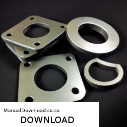
and torque specifications for your particular model.
A spark plug boot is an essential component of an internal combustion engine’s ignition system, playing a crucial role in the performance and efficiency of the engine. It is essentially the rubber or silicone covering that encases the end of the spark plug wire, which connects the ignition coil to the spark plug itself. The primary function of the spark plug boot is to ensure a secure electrical connection while protecting the wire from environmental factors such as heat, moisture, and contaminants.

Spark plug boots are designed to withstand extreme temperatures, as they are located in close proximity to the engine and subjected to significant thermal stress. They often feature a high-temperature resistant material that prevents deterioration over time, which is vital for maintaining the integrity of the ignition system. A well-functioning spark plug boot helps to ensure that the electrical current can travel efficiently from the ignition coil to the spark plug, igniting the air-fuel mixture in the combustion chamber.

Additionally, spark plug boots are designed with a specific shape and size to ensure a snug fit on both the spark plug and the ignition wire, minimizing the risk of misfiring or electrical leakage. Over time, these boots can wear out or become damaged, leading to issues such as poor engine performance, increased emissions, and difficulty starting the vehicle. Regular inspection and replacement of worn spark plug boots can contribute to the overall health of the engine, ensuring optimal ignition and fuel efficiency.

Download 2007 BMW 545i (E60) 5 Series OEM Download Service & Repair Manual Software –

service
Replacing the struts on a BMW 545i E60 can seem daunting, especially if you have little mechanical experience. click here for more details on the download manual…..


    BMW 545i stock exhaust This is before exhaust mods.

    2004 BMW 545i pass rear seats Car for sale.

However, with the right tools, patience, and careful steps, you can accomplish this task. Here’s a simplified guide to help you through the process.

### Tools and materials Needed:
– **Tools:**
– Socket set (with ratchet and extensions)
– Wrench set
torque wrench
– Strut spring compressor (essential for handling the spring safely)
– Jack and jack stands
– Screwdrivers
– Pliers
– Hammer (optional)

– **Materials:**
– New struts (make sure they are compatible with the BMW 545i E60)
– New strut mounts (recommended)
– New strut boots (if necessary)
– New bump stops (if necessary)
– Lubrication (like grease) for the mounts

### Safety Precautions:
1. **Work on a flat surface:** Make sure your car is parked on a level surface to prevent it from rolling.
2. **Use jack stands:** Never rely solely on a jack; always use jack stands for safety.
3. **Wear safety glasses and gloves:** Protect your eyes and hands from debris and sharp objects.

### Step-by-Step Guide:

#### Step 1: Prepare the Vehicle
1. **Loosen the lug nuts:** Before lifting the car, slightly loosen the lug nuts on the front wheels using a lug wrench. Don’t remove them yet.
2. **Lift the car:** Use a jack to lift the front of the car and then place it securely on jack stands. Ensure the vehicle is stable before proceeding.

#### Step 2: Remove the Wheels
1. **Remove the lug nuts:** Now you can fully remove the lug nuts and take off the front wheels. Set them aside in a safe place.

#### Step 3: Access the Strut Assembly
1. **Locate the strut assembly:** The strut is the large cylindrical component connected to the wheel hub and the vehicle chassis.
2. **Disconnect any components:** You may need to disconnect the brake line bracket, sensors, or other components that are attached to the strut. Be gentle to avoid damaging any wiring.

#### Step 4: Remove the Strut
1. **Remove the strut nuts on top:** Open the hood and locate the strut tower. You should see three nuts holding the top of the strut in place. Use a socket wrench to remove these nuts.
2. **Support the strut:** Use a jack or a piece of wood to support the bottom of the strut as you remove it.
3. **Remove the lower strut bolts:** At the bottom of the strut, there are usually two bolts connecting the strut to the wheel hub. Use a socket wrench to remove these bolts and gently pull the strut out.

#### Step 5: Replace the Strut
1. **Compress the spring:** If you are reusing the old spring, use a strut spring compressor to Safely compress the spring before removing it from the old strut. This is crucial for safety.
2. **Install the spring on the new strut:** Once the spring is compressed, carefully install it onto the new strut, following the manufacturer’s instructions.
3. **Reassemble the strut:** If you have new mounts or bump stops, install them on the new strut as well.

#### Step 6: Install the New Strut
1. **Position the new strut:** Carefully lift the new strut into place, aligning it with the bottom mount on the wheel hub.
2. **Secure the lower bolts:** Insertdownload BMW 545i E60 5 OEM workshop manual and tighten the lower bolts first.
3. **Secure the top of the strut:** Go back to the engine bay and secure the top of the strut by tightening the three nuts.

#### Step 7: Reassemble Everything
1. **Reconnect any components:** Reattach the brake line bracket, sensors, or any other components you disconnected earlier.
2. **Reinstall the wheel:** Put the wheel back on and hand-tighten the lug nuts.

#### Step 8: Lower the Car
1. **Remove the jack stands:** Carefully lower the car back to the ground using the jack.
2. **Tighten the lug nuts:** Once the car is on the ground, use a torque wrench to tighten the lug nuts to the manufacturer’s recommended torque specification.

#### Step 9: Test Drive
1. **Check for any issues:** Before taking a longer drive, do a short test drive to ensure everything feels right and there are no unusual noises.

### Final Thoughts
Strut replacement can be a challenging task, but by following these steps carefully, you can successfully complete it. If at any point you feel uncomfortable or unsure, don’t hesitate to consult a professional mechanic. Enjoy your newly improved ride!
A battery insulator is a crucial component in automotive and various electronic applications that serves multiple important functions related to the battery. Typically made from materials with excellent insulating properties, such as rubber, plastic, or specialized composites, a battery insulator is designed to prevent short circuits by providing a barrier between the battery terminals and other conductive surfaces. This is particularly vital in vehicles where vibrations and movements can cause components to shift, potentially leading to unintended contact and electrical failures.

In addition to preventing electrical shorts, battery insulators also play a role in protecting the battery from environmental factors such as moisture, dirt, and thermal fluctuations. Many insulators are designed to be weather-resistant, ensuring that the battery remains operational in various conditions, from extreme heat to freezing cold. This protection helps extend the battery’s lifespan and maintain its performance.

Moreover, battery insulators can contribute to the overall safety of the vehicle. By containing any potential leaks from the battery, they help minimize the risk of hazardous spills that could occur in the event of an accident or battery failure. Some insulators are also designed to dampen vibrations, which can further protect the battery and enhance durability.

In summary, battery insulators are vital for ensuring the safety, efficiency, and longevity of batteries in vehicles and other electronic systems, making them a key component in modern automotive engineering.

Download 2010 Subaru Outback / Legacy Outback Service & Repair Manual –

service
Certainly! click here for more details on the download manual…..


    TOP 9 Most Common Subaru Outback Problems https://amzn.to/43i0HtT – All-in-One OBDII Car Scanner In this short video we will talk abouth the most common Subaru Outback …

    What Tools Are Included in The Trunk Of A Subaru Outback? | Hawk Subaru of Joliet If you purchased a New Subaru in Frankfort, you may be wondering what tools come in the trunk of the Subaru Outback. Cole from …

Here’s a detailed guide on how to replace the battery in a Subaru Outback or Legacy, presented in bullet points for clarity:

### Tools Required:
– **New Battery**: Ensure it is the correct size and type for your specific model.
– **Wrench Set**: Usually a 10mm socket or wrench for the battery terminals.
– **Battery Terminal Cleaner**: A wire brush or terminal cleaner tool to clean corroded terminals.
– **Safety Gloves**: To protect your hands from battery acid and debris.
– **Safety Goggles**: To protect your eyes from any sparks or debris.
– **Flashlight**: Helpful for seeing in the engine bay, especially if it’s dark.

### Battery Replacement Steps:

– **Preparation**:
– Park your Subaru on a flat surface and turn off the ignition.
– Ensure the vehicle is in park (automatic) or in gear (manual) and engage the parking brake.
– Remove any accessories that might be connected to the battery, such as phone chargers or GPS devices.

– **Open the Hood**:
– Pull the hood release lever inside the vehicle.
– Go to the front of the vehicle and release the hood latch to open the hood fully.

– **Locate the Battery**:
– Identify the battery, which is usually located on the driver’s side of the engine compartment.
– Make sure there’s enough light to see the battery connections clearly.

– **Disconnect the Negative Terminal**:
– Use the wrench or socket to loosen the nut on the negative terminal (black).
– Once loose, carefully pull the cable off the terminal and secure it away from the battery to avoid accidental reconnection.

– **Disconnect the Positive Terminal**:
– Repeat the process for the positive terminal (red), loosening the nut and removing the cable.
– Again, keep the cable away from the battery to prevent short-circuiting.

– **Remove Any Battery Hold-Down Clamp**:
– Check for any hold-down bracket or clamp securing the battery in place.
– Use the appropriate socket or wrench to unscrew and remove this clamp.

– **Remove the old Battery**:
– Carefully lift the battery out of the tray. Batteries can be heavy, so use proper lifting techniques.
– Place the old battery aside in a safe location.

– **Clean the Battery Tray and Terminals**:
– Use the battery terminal cleaner or a wire brush to clean any corrosion from the battery tray and terminals.
– Wipe down the area with a cloth to remove any debris.

– **Install the New Battery**:
– Place the new battery into the battery tray, ensuring it’s oriented correctly (positive and negative terminals positioned as the old battery).
reinstall the hold-down clamp to secure the battery in place.

– **Reconnect the Positive Terminal**:
– Attach the positive cable first (red). Slide it onto the positive terminaldownload Subaru Outback Legacy Outback workshop manual and tighten the nut securely.

– **Reconnect the Negative Terminal**:
– Next, attach the negative cable (black) to the negative terminal and tighten it securely.

– **Check Connections**:
– Ensure both terminals are tight and secure. A loose connection can lead to starting issues.

– **Final Steps**:
– Close the hood securely.
start the vehicle to ensure the new battery is functioning properly.

– **Dispose of the old Battery**:
– Take the old battery to a recycling center or automotive store that accepts used batteries for safe disposal.

### Safety Tips:
– Always wear safety gloves and goggles when working with car batteries to protect against acid and sparks.
– Be cautious of any tools slipping while working near the battery terminals to avoid short-circuiting.

By following these detailed steps, you should be able to successfully replace the battery in your Subaru Outback or Legacy.
An intercooler is a crucial component in turbocharged and supercharged internal combustion engines, designed to enhance engine performance and efficiency. Its primary function is to cool the compressed air that has been heated during the compression process. When air is compressed, its temperature increases, which can lead to reduced efficiency and increased chances of engine knock—an undesirable condition where fuel detonates prematurely. By cooling the air before it enters the combustion chamber, an intercooler allows for denser air to be mixed with fuel, resulting in a more efficient combustion process.

Intercoolers typically come in two types: air-to-air and air-to-water. Air-to-air intercoolers use ambient air to cool the compressed intake air, relying on airflow generated by the vehicle’s motion. They are generally mounted in front of the vehicle’s radiator, where they can maximize contact with the cooler external air. In contrast, air-to-water intercoolers use water as a coolant, which can be more effective in reducing temperatures in tight engine spaces, though they require a more complex system with a heat exchanger.

The benefits of an intercooler include increased horsepower, improved throttle response, and enhanced engine longevity due to reduced thermal stress. Overall, intercoolers play a vital role in maximizing the performance of forced induction engines, ensuring that they operate efficiently and reliably under demanding conditions.

Download Land CRUISER PRADO Electrical Wiring Diagram Manual –

australia
Replacing the sway bar links on a Toyota Land Cruiser Prado involves several steps. click here for more details on the download manual…..


    WHEEL BEARINGS INFORMATION – AVOID PROBLEMS – THEN TYRE REVIEW / FEEDBACK Firstly some information to do with front wheel bearings on any vehicle avoid over loading them when pressing them. Use the talk …

    CHANGING FRONT WHEEL BEARINGS ON FRONT LANDCRUISER PRADO DRIVERS SIDE Toyota Prado front bearing replacement LC120 LC150 same job. Fourby4diesel Buying new front wheel bearings Changing the …

Below is a detailed guide presented in bullet points, which includes the tools required and step-by-step instructions.

### Tools and Materials Needed:
– **Socket set**: Includes metric sockets (typically 10mm, 14mm, and 17mm)
– **Ratchet and extension**: For reaching tight spots
– **Wrench set**: Open-end and box-end wrenches for various bolt sizes
– **Torque wrench**: Ensures bolts are tightened to the manufacturer’s specifications
– **Pry bar or flathead screwdriver**: To help in displacing components if necessary
– **Jack and jack stands**: To lift the vehicle safely
– **Wheel chocks**: Prevents the vehicle from rolling
– **Lubricant (WD-40 or similar)**: To loosen rusted or stuck bolts
– **Replacement sway bar links**: Ensure they are compatible with the model year of your Prado
– **Safety goggles and gloves**: To protect yourself during the process

### Step-by-Step Replacement Instructions:

– **Preparation**:
– Park the vehicle on a level surface and engage the parking brake.
– Place wheel chocks behind the rear wheels to prevent movement.

– **Lifting the Vehicle**:
– Use a jack to lift the front of the vehicle, then secure it with jack stands.
– Ensure the vehicle is stable before proceeding.

– **Removing the Wheel**:
– Use a lug wrench to loosen and remove the lug nuts on the front wheels.
– Take off the wheel to expose the suspension components.

– **Locating the Sway Bar Links**:
– Identify the sway bar links, which connect the sway bar to the suspension components (usually the control arm).

– **Inspecting Existing Links**:
– Check for signs of wear, such as cracks or excessive play in the bushings. This will confirm the need for replacement.

– **Loosening the Bolts**:
– Apply lubricant to the sway bar link bolts if they appear rusted or stuck.
– Use the appropriate socket and ratchet to loosen the top and bottom bolts of the sway bar link. Hold the other side with a wrench if necessary to prevent it from spinning.

– **Removing the Sway Bar Link**:
– Once the bolts are removed, carefully pull the sway bar link out from the sway bar and control arm.

– **Preparing the New Sway Bar Link**:
– Compare the new sway bar link to the old one to ensure they are identical in length and design.
– If the new link comes with new bushings or washers, ensure they are installed as per the manufacturer’s instructions.

– **Installing the New Sway Bar Link**:
– Position the new sway bar link in place, aligning it with the sway bar and control arm.
– Install the bolts by hand to avoid cross-threading, then tighten them with a socket and ratchet.

– **Torque Specification**:
– Use a torque wrench to tighten the sway bar link dispose of any old parts responsibly.

Following these steps will help ensure a successful sway bar link replacement on your Land Cruiser Prado. Always refer to the vehicle’s service manual for specific details and torque specifications for your model year.
A Constant Velocity (CV) joint is a crucial component of a vehicle’s drivetrain, primarily found in front-wheel drive and all-wheel drive vehicles. Its primary function is to transmit torque from the engine to the wheels while allowing for the necessary movement of the suspension. The CV joint enables the wheels to turn at different angles while maintaining a constant rotational speed, which is essential for smooth handling and stability, especially during turns.

There are two main types of CV joints: the ball-type and the tripod-type. The ball-type CV joint is typically used on the outer end of the axle, where the wheel connects, while the tripod-type is generally found on the inner end, connecting the axle to the transmission. The ball-type joint consists of a spherical outer casing with several balls that allow for flexibility in various directions, while the tripod joint features three prongs that fit into a socket, providing angular movement.

One of the key advantages of CV joints is their ability to handle significant angles without losing power transfer efficiency. This is particularly important in vehicles with independent suspension systems, where wheel movement can vary greatly. Over time, CV joints can wear out or become damaged, often indicated by clicking or popping noises during turns. Regular inspection and maintenance are essential to ensure their longevity and the overall performance of the vehicle, as a failing CV joint can lead to more severe mechanical issues and safety concerns.

Download Hyundai R55-7A Crawler Excavator Factory Service Repair Manual-

workshop manual
Replacing the timing chain on a Hyundai R55 7A Crawler Excavator is a complex task that requires a good understanding of the engine components and careful attention to detail. click here for more details on the download manual…..


    Hyundai R380LC-9 Excavator Hydraulic Flow Adjustment to the Thumb http://www.sheelysupply.com Procedure to adjust the speed of the the thumb cylinder. Speed up or slow down. Industrial Diesel …

    Hyundai R380LC-9 Excavator Hydraulic Flow Adjustment to the Thumb http://www.sheelysupply.com Procedure to adjust the speed of the the thumb cylinder. Speed up or slow down. Industrial Diesel …

Below is a detailed step-by-step guide to assist you in this process. Before you start, ensure that you have the necessary tools and safety equipment.

### Tools and Materials Required:
1. **Tools**:
– Socket set (metric)
– Torque wrench
– Screwdrivers (flat and Phillips)
– Pliers
timing chain tool kit (if available)
– Oil filter wrench
– Engine lifting equipment (if necessary)
– Crankshaft pulley holder tool

2. **Materials**:
– New timing chain
timing chain tensioner (if applicable)
timing chain guides (if applicable)
– Engine oil
gasket sealant (if applicable)
– New oil filter
– New engine oil (if applicable)

3. **Safety Equipment**:
– Safety gloves
– Safety glasses
– Dust mask

### Step-by-Step Procedure:

#### 1. Preparation:
– **Read the Manual**: Before beginning the work, read the service manual for your specific model to familiarize yourself with the engine layout and timing chain specifications.
– **Safety First**: Ensure the excavator is parked on a level surface, the engine is turned off, and the key is removed. Engage the parking brake.

#### 2. remove Engine Covers:
– **Access the Engine**: Depending on the machine, you might need to remove protective covers to access the engine. Use your socket set to remove any screws or bolts securing these covers.

#### 3. Drain Engine Oil:
– **Oil Drain**: Place a pan underneath the oil pan and remove the oil drain plug to drain the engine oil. Allow it to drain completely.

#### 4. remove the timing Chain Cover:
– **Timing Cover Removal**: Using your socket set, remove the bolts securing the timing chain cover. Carefully pry the cover off, ensuring not to damage the gasket or the cover itself.

#### 5. Align timing Marks:
– **Crankshaft and Camshaft Alignment**: Rotate the crankshaft using a socket on the crankshaft pulley to align the timing marks on the crankshaft and camshaft. This is crucial for ensuring the proper timing of the engine after the chain is replaced.

#### 6. remove the Old timing Chain:
– **Timing Chain Removal**: If applicable, remove the tensioner and guides. Then, carefully remove the old timing chain from the sprockets. Note the orientation and position of the chain and any guides for reinstallation.

#### 7. Install the New timing Chain:
– **New timing Chain Installation**: Place the new timing chain onto the sprockets, ensuring it is correctly aligned with the timing marks. If there are guides or tensioners, install them according to the specifications provided in the service manual.

#### 8. Adjust the Tensioner:
– **Timing Chain Tensioner**: If your model has a timing chain tensioner, make sure it is properly adjusted according to the manufacturer’s specifications. This is crucial for maintaining the correct tension on the timing chain.

#### 9. Reassemble the timing Cover:
– **Timing Cover Reinstallation**: Clean the mating surfaces of the timing coverdownload Hyundai R55 7A Crawler Excavator Manual workshop manual and engine. Apply gasket sealant if required, and then reinstall the timing cover. Ensure all bolts are tightened to the torque specifications indicated in the service manual.

#### 10. Refill Engine Oil:
– **Oil Refill**: Replace the oil drain plug and refill the engine with new oil through the oil filler cap. consult the manual for the correct oil type and capacity.

#### 11. Replace Oil Filter:
– **Oil Filter**: If necessary, replace the oil filter using an oil filter wrench. Make sure to apply a small amount of oil to the rubber O-ring of the new filter before installation.

#### 12. Final Checks:
– **Check All Connections**: Ensure that all hoses, wires, and connections are properly secured.
– **Reinstall Engine Covers**: If you removed any other engine covers, reinstall them.

#### 13. Start the Engine:
– **Testing**: Start the engine and let it run for a few minutes while checking for any leaks or unusual noises. Monitor the oil pressure and ensure everything is functioning properly.

#### 14. Dispose of Waste Materials:
– **Clean Up**: Properly dispose of the old oil, oil filter, and any other waste materials according to local regulations.

### Conclusion:
Replacing the timing chain on a Hyundai R55 7A Crawler Excavator is an intricate task that requires precision and attention to detail. Always refer to the official service manual for specific torque specifications and other details related to your particular engine model. If you are not comfortable performing this task, it is recommended to seek assistance from a qualified mechanic.
Car speakers are crucial components of a vehicle’s audio system, designed to reproduce sound, including music, navigation prompts, and other audio signals. Typically located in various parts of the car—such as the doors, dashboard, and rear parcel shelf—speakers convert electrical signals from the car’s stereo system into audible sound waves.

Car speakers come in several types, including coaxial (full-range) speakers and component speakers. Coaxial speakers integrate multiple speaker elements into a single unit, allowing for a compact design and broader sound coverage. Component speakers, on the other hand, separate the different sound frequencies—such as highs, mids, and lows—into distinct units, providing superior sound quality and clarity. This separation allows for better audio performance, as each unit can be optimized for its specific frequency range.

The materials used in car speakers also play a significant role in their performance. Common components include paper, polypropylene, and various synthetic materials for the cone, while the surround may be made from rubber or foam. The speaker’s size, typically measured in inches, affects its sound output, with larger speakers generally capable of producing deeper bass.

In modern vehicles, advancements in technology have led to the integration of features such as Bluetooth connectivity, allowing for wireless streaming from smartphones and other devices. High-end models may also include subwoofers for enhanced bass response and additional amplifiers to drive the speakers more effectively. Overall, car speakers significantly enhance the driving experience by providing high-quality audio that can make journeys more enjoyable.

Download Chrysler 1993 AS Town Country Caravan Voyager Electronic Ser –

book shop
Repairing a suspension knuckle on a Chrysler Town & Country or Dodge Caravan/Voyager involves several steps, tools, and components. click here for more details on the download manual…..


    TOWN & COUNTRY CARAVAN NO BUS DIAGNOSTIC Customer brought in a 2014 Chrysler Town and Country minivan. The vehicle runs and drives fine, but many of the accessories …

    Chrysler Town & Country 2009 3.8L V6 ticking noise

The suspension knuckle, also known as the steering knuckle, supports the wheel and connects the suspension components to the wheel hub. Here’s a detailed guide on how to perform this repair:

### Tools and Equipment Needed

1. **Tools:**
– Jack and jack stands
– Lug wrench
– Ratchet and socket set (including deep sockets)
– Torque wrench
– Pliers
– Hammer or mallet
– Ball joint separator or pickle fork
– Screwdrivers
– Pry bar
– Torque specs for the vehicle

2. **Replacement Parts:**
– New suspension knuckle (if damaged)
– New wheel bearing (if necessary)
– New ball joints (if required)
– New tie rod end (if required)
– New hardware (such as nuts, bolts, or washers)

3. **Safety Equipment:**
– Safety glasses
– Gloves
– Work gloves

### Procedure

#### Step 1: Preparation and Safety

1. **Park the Vehicle**: Ensure the vehicle is on a flat, level surface.
2. **Engage the Parking Brake**: This prevents the vehicle from rolling.
3. **Gather Tools**: Assemble all necessary tools and replacement parts.

#### Step 2: Raise the Vehicle

1. **Loosen Lug Nuts**: Before lifting, use a lug wrench to loosen the lug nuts on the wheel where the knuckle is being repaired. Do not remove them yet.
2. **Lift the Vehicle**: Use a jack to lift the vehicle at the designated lift points.
3. **Secure with Jack Stands**: Place jack stands under the vehicle for safety.
4. **Remove Wheel**: Finish removing the lug nuts and take off the wheel.

#### Step 3: Remove the Old Suspension Knuckle

1. **Disconnect Brake Line**: If necessary, unbolt the brake line from the knuckle and secure it to avoid stress on the line.
2. **Remove the Brake Caliper**:
– Use a ratchet to unbolt the caliper from its bracket.
– Support the caliper with a bungee cord or wire to avoid hanging it by the brake line.
3. **Remove the Brake Rotor**: If it doesn’t come off easily, gently tap it with a hammer.
4. **Disconnect the Tie Rod End**:
– Remove the cotter pin from the tie rod end and use a ball joint separator to disconnect it from the knuckle.
5. **Remove the Lower Ball Joint**:
– If necessary, remove the lower ball joint by unbolting it from the knuckle. Use a ball joint separator if it is stuck.
6. **Remove the Upper Ball Joint**:
– If applicable, repeat the procedure for the upper ball joint.
7. **Disconnect the Axle Shaft**: If the knuckle is connected to the axle, remove the axle nut and pull the axle out of the knuckle.
8. **Remove the Knuckle**:
– Unbolt the suspension knuckle from the strut assembly. There may be two or three bolts holding it in place.
– Carefully remove the knuckle from the vehicle.

#### Step 4: Install the New Suspension Knuckle

1. **Prepare the New Knuckle**:
– If necessary, install new bearings into the new knuckle.
2. **Install the New Knuckle**:
– Position the new knuckle in place and bolt it to the strut assembly. Ensure all bolts are tightened to the manufacturer’s torque specifications.
3. **Reconnect the Axle Shaft**: If applicable, Insert the axle into the knuckle and secure it with the axle nut.
4. **Install the Upper Ball Joint**:
– If applicable, Insert the upper ball joint into the knuckle and secure it.
5. **Install the Lower Ball Joint**:
– Repeat for the lower ball joint.
6. **Reconnect the Tie Rod End**: Secure it back into the knuckledownload Chrysler AS Town Country Caravan Voyager Ser workshop manual and install a new cotter pin.
7. **Reinstall the Brake Rotor**: Slide the rotor back onto the hub.
8. **Reinstall the Brake Caliper**: Position it back onto the brake rotor and tighten the bolts securely.
9. **Reconnect the Brake Line**: If you disconnected it earlier, reattach it now.

#### Step 5: Reassemble and Finalize

1. **Reinstall the Wheel**: Place the wheel back onto the hub, hand-tightening the lug nuts.
2. **Lower the Vehicle**: Remove the jack stands and carefully lower the vehicle back to the ground.
3. **Torque the Lug Nuts**: Once the vehicle is back on the ground, use a torque wrench to tighten the lug nuts to the manufacturer’s specifications.
4. **Check for Proper Function**: Before driving, ensure that all components are correctly installed and functioning.

#### Step 6: Test Drive and Inspection

1. **Test Drive**: Take the vehicle for a short test drive to ensure everything is functioning correctly.
2. **Inspect for Noise or Vibration**: Listen for any unusual sounds or vibrations, which could indicate a problem.

### Conclusion

Repairing the suspension knuckle on a Chrysler Town & Country or Dodge Caravan/Voyager is a complex task that requires careful attention to detail, proper tools, and safety precautions. If you are not confident in your ability to perform this repair, it is advisable to consult a professional mechanic. Always refer to the service manual for your specific vehicle for torque specifications and detailed procedures.
The blower motor is a crucial component of a vehicle’s heating, ventilation, and air conditioning (HVAC) system. Its primary function is to circulate air throughout the cabin, ensuring a comfortable environment for passengers regardless of external weather conditions. The blower motor works by drawing air from outside or recirculating air from inside the vehicle and pushing it through the heating or cooling system, depending on the desired temperature setting.

Typically located within the dashboard or under the hood, the blower motor is an electric fan that operates at varying speeds, controlled by the vehicle’s HVAC controls. When the driver or passengers adjust the temperature settings, the blower motor responds by increasing or decreasing its speed, allowing for customized airflow. This component is also responsible for directing air through the vents, defrosters, and other outlets, enhancing visibility during inclement weather by preventing fogging on the windshield.

Over time, blower motors can experience wear and tear, leading to issues such as reduced airflow, unusual noises, or complete failure. regular maintenance and timely replacement of a malfunctioning blower motor are essential to ensure the HVAC system operates efficiently and effectively. Overall, the blower motor plays a vital role in enhancing passenger comfort and vehicle safety by maintaining optimal air quality and temperature inside the car.

Download Aston Martin V8 Vantage 2008 Factory Service Repair Manual –

bookstore
Replacing the torque converter on an Aston Martin V8 Vantage is a complex process that involves a number of steps and components. click here for more details on the download manual…..


    Coilovers or Motorsport Shocks, again!? QOTW #77 Coilovers or Motorsport Shocks, again!? QOTW #77 Enter our Instagram giveaway: …

    Aston Martin Vantage GT8 driven by The Stig at the Ignition Festival of Motoring 2016 Racing is in Aston Martin’s blood. From outright victory at Le Mans 24 Hours in 1959, to countless race wins in GT3 and GT4 …

below is a detailed guide on how to perform this task. Please note that this is a high-level overview, and actual procedures may vary based on specific vehicle configurations and the tools available. Always refer to the manufacturer’s service manual for specific instructions and safety guidelines.

### Tools and Equipment Needed

1. **Basic Hand Tools:**
socket set (metric and standard)
– Wrenches (metric and standard)
– Screwdrivers (flathead and Phillips)
– Pliers
– Torque wrench
– Ratchet and extensions

2. **Specialized Tools:**
– Transmission jack or engine hoist
– Torque converter alignment tool
– Oil catch pan
– Transmission fluid pump (if needed)
– Flywheel holding tool (if applicable)

3. **Replacement Parts:**
– New torque converter
– New transmission fluid and filter
– New gaskets and seals
– Any additional hardware as needed (e.g., bolts, nuts)

4. **Safety Equipment:**
– Gloves
– Safety goggles
– Mechanic’s creeper

### Preparation

1. **Safety First:**
– Disconnect the battery to prevent any electrical shorts or shocks.
– Ensure the vehicle is on a stable surface and secured with wheel chocks.

2. **Lift the Vehicle:**
– Use a hydraulic lift or jack stands to elevate the vehicle safely.

3. **Drain Transmission Fluid:**
– Place an oil catch pan under the transmission pan.
– Remove the transmission pan bolts and allow the fluid to drain completely.

### Removal of the Old Torque Converter

1. **Accessing the Transmission:**
– Remove any components obstructing access to the transmission, such as the exhaust system, driveshaft, and any crossmembers.
– Disconnect the transmission cooler lines, noting their positions for reinstallation.

2. **Disconnect Electrical Connectors:**
– Remove any electrical connectors attached to the transmission, including those for the transmission control module (TCM).

3. **Support the Transmission:**
– Place a transmission jack under the transmission to support its weight.

4. **Remove the Transmission:**
– Unbolt the transmission from the engine. This typically involves removing the bell housing bolts and any additional mounting bolts.
– Carefully lower the transmission away from the engine and set it aside.

5. **Remove the Old Torque Converter:**
– The torque converter is typically bolted to the flexplate. Remove these bolts while supporting the torque converter.
– Once unbolted, carefully pull the torque converter off the transmission input shaft and remove it from the vehicle.

### Installation of the New Torque Converter

1. **Prepare the New Torque Converter:**
– Inspect the new torque converter for any damage.
– Fill the new torque converter with transmission fluid to ensure proper lubrication upon startup.

2. **Install the New Torque Converter:**
– Align the torque converter with the input shaft of the transmission and slide it into place.
– Ensure that it is seated correctly against the pump in the transmission.

3. **Reattach the Transmission:**
– Carefully raise the transmission back into position using the transmission jack.
– Align the torque converter with the flexplatedownload Aston Martin V8 Vantage workshop manual and secure it with the appropriate bolts.
– Torque the bolts to the manufacturer’s specifications.

4. **Reconnect All Components:**
– Reinstall any components removed earlier, including the driveshaft, exhaust system, and any crossmembers.
– Reconnect the transmission cooler lines and electrical connectors.
– Install a new transmission filter and gasket, and reattach the transmission pan.

### Final Steps

1. **Refill Transmission Fluid:**
– Use a transmission fluid pump to refill the transmission with the appropriate type and amount of fluid.

2. **Reconnect the Battery:**
– Reconnect the battery terminals.

3. **Test the Installation:**
– Start the engine and allow it to warm up.
– Check for leaks and ensure that the transmission engages properly in all gears.

4. **Test Drive:**
– Conduct a short test drive to ensure that the torque converter and transmission are functioning correctly.

### Conclusion

Replacing the torque converter in an Aston Martin V8 Vantage is a detailed and labor-intensive process that requires significant mechanical knowledge and skill. It is highly recommended to consult the vehicle’s service manual and, if unsure, seek assistance from a professional mechanic. Proper tools, safety precautions, and attention to detail are crucial for a successful installation.
A sunroof is a type of car component that serves as an opening in the roof of a vehicle, allowing natural light and fresh air to enter the cabin. Typically made of glass, a sunroof can be either fixed or operable. Fixed sunroofs are sealed and do not open, primarily designed to enhance the aesthetic appeal of the car and provide additional light to the interior. In contrast, operable sunroofs can be opened either by sliding back or tilting, giving passengers the option to enjoy the open air while driving.

Sunroofs come in various styles and designs, including pop-up, tilt-and-slide, and panoramic options. The pop-up sunroof opens to a limited degree, providing ventilation without fully retracting. Tilt-and-slide sunroofs, on the other hand, can be tilted upwards or slid back completely, allowing for greater airflow and exposure to the elements. Panoramic sunroofs are larger and often extend over both the front and rear seats, creating a sense of spaciousness and an expansive view of the sky.

In addition to their aesthetic and functional benefits, sunroofs can enhance the driving experience by allowing occupants to connect with the environment, making journeys more enjoyable. However, they can also add weight to the vehicle and might impact structural integrity if not designed correctly. Overall, sunroofs are a popular feature in modern vehicles, appealing to drivers who value both style and versatility in their automotive experience.