Download Ford 555 Tractor Backhoe Loader Service Repair Manual –

purchase
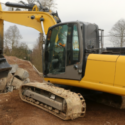
Replacing a planetary gear set in a Ford 555 Tractor Backhoe Loader is a complex task that requires mechanical skill and understanding of heavy machinery. click here for more details on the download manual…..


    MY Ford Tractor Loader Backhoe will not go forward or reverse For those on the forums and google looking for info on why your Ford Tractor Loader or backhoe With the Power reverser …

    FORD 555 BACKHOE REPAIRS. FORD 555 Backhoe repairs, Nothing major but stuff that needs to be fixed on the new to me Ford dirt swinger. If your new to the …

This guide will provide a detailed overview of the components involved and the steps necessary to complete the replacement.

### Tools and Equipment Needed

1. **Basic Hand Tools**: Wrenches, sockets, ratchets, and screwdrivers.
2. **Torque Wrench**: For accurate torque specifications.
3. **Hydraulic Jack and Jack Stands**: For lifting the machine safely.
4. **Pry Bars**: To help remove stubborn components.
5. **Bearing Puller**: Useful for removing bearings.
6. **Seal Puller**: For removing seals without damaging the housing.
7. **Clean Rags and Cleaning Solvent**: For cleaning surfaces.
8. **Grease and Lubricants**: For reassembly.
9. **Service Manual**: Specific to the Ford 555 for torque specs and detailed diagrams.

### Components Involved

1. **Planetary Gear Set**: The assembly that includes:
– **Sun Gear**: The central gear that drives the planet gears.
– **Planet Gears**: The gears that revolve around the sun gear and are mounted on a carrier.
– **Ring Gear**: The outer gear that meshes with the planet gears.
– **Carrier**: Holds the planet gears in place and transfers torque.

2. **Hydraulic Motor**: Provides the necessary power to drive the planetary gear set.

3. **Housing**: The case that contains the planetary gear set and keeps everything in alignment.

4. **Seals and Gaskets**: prevent fluid leaks and contain lubrication.

5. **Bearings**: Support the gears and allow for smooth rotation.

### Steps for Replacement

1. **Preparation**
– Ensure the tractor is on a flat, stable surface and turn off the engine.
– Disconnect the battery to prevent accidental starts.
– Use the hydraulic jack to lift the rear of the tractor and secure it with jack stands.

2. **Remove the Backhoe Assembly**
– Disconnect hydraulic lines leading to the backhoe.
– Remove the pins and brackets securing the backhoe to the tractor frame.
– Carefully lift and set the backhoe assembly aside.

3. **Access the Transmission Housing**
– Remove the access panel or cover on the transmission housing to expose the planetary gear set.

4. **Drain Fluid**
– Drain the hydraulic fluid from the transmission to prevent spills and contamination.

5. **Remove the Planetary Gear Set**
– Unscrew any bolts securing the planetary gear set housing.
– Carefully remove the housing to expose the gear set.
– Take note of the arrangement of gears and carriers for reassembly.
– Use the bearing puller if necessary to remove the planet gears and carrier.
– Remove the sun gear and ring gear as needed.

6. **Inspect Components**
– Inspect the sun gear, planet gears, and ring gear for wear or damage.
– Check bearings and seals for signs of wear; replace if necessary.

7. **Install the New Planetary Gear Set**
– Begin by placing the new sun gear into position.
– Install the planet gears onto the carrier, ensuring they mesh properly with the sun gear.
– Attach the ring gear to the housing, ensuring it aligns correctly with the planet gears.
– Secure all components in place with the appropriate fasteners, torquing them to specification.

8. **Reassemble the Transmission Housing**
– Replace any sealsdownload Ford 555 Tractor Backhoe Loader workshop manual and gaskets before reattaching the housing cover.
– Ensure all bolts are tightened to the required torque specifications.

9. **Reconnect the Backhoe Assembly**
– Reattach the backhoe to the tractor frame, ensuring all pins and brackets are secure.
– Reconnect hydraulic lines, checking for proper connections.

10. **Refill Fluid**
– Refill the hydraulic system with the appropriate hydraulic fluid as per the service manual.

11. **Test the System**
– Reconnect the battery and start the tractor.
– Test the backhoe and planetary gear operation to ensure everything is functioning correctly.

### Final Checks

– **Leak Inspection**: After running the tractor, inspect for any leaks around the seals and gaskets.
– **Function Test**: Operate the backhoe to ensure smooth operation without unusual noises.

### Conclusion

Replacing a planetary gear set in a Ford 555 Tractor Backhoe Loader is a detailed process that requires careful attention to detail and proper reassembly. Always refer to the manufacturer’s service manual for specific torque specifications and additional instructions for your particular model. If you’re not comfortable performing this task, consider consulting a professional mechanic.
A brake line is a crucial component of a vehicle’s braking system, responsible for transferring hydraulic pressure from the brake pedal to the brake calipers or brake drums at each wheel. Brake lines are typically made from high-strength materials such as steel or reinforced rubber, designed to withstand the high pressures generated when the brakes are applied. The primary function of the brake line is to convey the brake fluid, which is essential for the hydraulic braking mechanism to function effectively.

When a driver presses the brake pedal, the force is transmitted through the master cylinder, which generates hydraulic pressure in the brake fluid. This pressure travels through the brake lines to the brake calipers (in disc brake systems) or brake cylinders (in drum brake systems), causing them to engage and apply friction to the brake rotors or drums. This friction is what ultimately slows down or stops the vehicle.

Brake lines are designed to handle extreme conditions, including high temperatures and exposure to road debris and chemicals. Over time, however, they can develop issues such as leaks, corrosion, or wear, which can compromise braking performance and pose significant safety risks. Regular inspection and maintenance of brake lines are essential to ensure they remain in good condition, as any failure in this component can lead to brake failure, endangering the vehicle occupants and others on the road.

Download service & repair manual Komatsu 170-3 series –

online
Controlling arm replacement on a Komatsu 170-3 requires careful execution and the right tools. click here for more details on the download manual…..


    Komatsu PC170LC Excavator from Kirby-Smith Machinery is Fast & Comfortable for LASAL, LLC See why this Komatsu PC170LC Excavator from Kirby-Smith Machinery is Fast & Comfortable for LASAL, LLC.

    گیربکس لودرWA470_3 کوماتسو #کوماتسو #گیربکس #لودر #komatsu #WHE…

Below are detailed steps and the tools needed for the process:

### Tools Required:
– **Socket Set**: A comprehensive socket set (including metric sizes) will be needed to remove bolts from the control arm assembly.
– **Wrench Set**: A combination of open-end and box-end wrenches for tightening and loosening nuts and bolts.
– **Torque Wrench**: For ensuring that all bolts are tightened to the manufacturer’s specifications.
– **Pry Bar**: To help in separating parts if they are stuck or difficult to remove.
– **Hammer**: A rubber mallet or dead blow hammer can be used to gently tap components without damaging them.
– **Jack and Jack Stands**: To safely lift and support the vehicle while working underneath it.
– **Pneumatic or Electric Impact Wrench**: For quickly removing stubborn bolts.
– **Suspension Tool Kit**: May include specialized tools for bushings or ball joints if applicable.
– **Safety Gear**: Gloves, safety glasses, and steel-toed boots for personal protection.
– **Grease or Lubricant**: To ease the installation of new components and prevent corrosion.

### Replacement Procedure:
– **Preparation**:
– Park the Komatsu 170-3 on a level surface.
– Engage the parking brake and turn off the ignition.
– Place wheel chocks around the wheels to prevent rolling.

– **Lifting the Vehicle**:
– Use the jack to lift the vehicle at the designated lift points.
– Secure the vehicle with jack stands to ensure it remains stable during the replacement process.

– **Removing the Wheel** (if necessary):
– If the control arm is obstructed by the wheel, remove the wheel by loosening the lug nuts with the socket set and then taking off the wheel.

– **Disconnecting Components**:
identify and remove any components connected to the control arm, such as sway bar links or shock absorbers, using the appropriate tools.
– Using the impact wrench or socket set, remove the bolts securing the control arm to the chassis and the spindle/knuckle.

– **Removing the Old Control Arm**:
– Once all bolts are removed, gently pry the control arm away from its mounting points using a pry bar.
– Inspect the old control arm for wear or damage before discarding it.

– **Preparing for New Control Arm Installation**:
– Clean the mounting surfaces on the chassis and spindle to ensure a good fit for the new control arm.
– Apply grease or lubricant to the bolts and bushings of the new control arm for easier installation.

– **Installing the New Control Arm**:
– Position the new control arm in place and align it with the mounting holes.
– Insert the bolts and hand-tighten them to hold the control arm in position.

– **Tightening Bolts**:
– Using the torque wrench, tighten the bolts to the manufacturer’s specifications, ensuring each bolt is properly secured.
– Reattach any components that were disconnected earlier, such as sway bar links or shock absorbers.

– **Reinstalling the Wheel** (if removed):
– Place the wheel back on the hubdownload Komatsu 170 3 workshop manual and hand-tighten the lug nuts.
– Use the torque wrench to tighten the lug nuts to the manufacturer’s specifications.

– **Lowering the Vehicle**:
– Carefully remove the jack stands and lower the vehicle back to the ground using the jack.
– Re-check the lug nuts and ensure everything is secure.

– **Final Inspection**:
– Before operating the machine, double-check all connections and components.
– Take the vehicle for a short test drive to ensure that everything is functioning properly and that there are no unusual noises or handling issues.

### Disposal:
– Dispose of the old control arm and any other removed components according to local regulations.

By following these steps and using the appropriate tools, you can effectively replace the control arm on a Komatsu 170-3. Always refer to the specific service manual for detailed specifications and torque values related to your model.
The gearbox, also known as a transmission, is a critical component of a vehicle’s drivetrain, responsible for transferring power from the engine to the wheels. It plays a vital role in enabling the vehicle to operate efficiently across a range of speeds and driving conditions. Essentially, the gearbox allows the engine to run at its optimal speed while providing the necessary torque to propel the vehicle forward.

There are two primary types of gearboxes: manual and automatic. A manual gearbox requires the driver to engage the gears by using a clutch pedal and Gear stick, allowing for greater control over the vehicle’s performance. In contrast, an automatic gearbox shifts gears automatically based on the vehicle’s speed and engine load, providing a more convenient driving experience.

Gearboxes consist of various gears, shafts, and other mechanical components that work together to alter the torque and speed delivered to the wheels. The Gear ratios determine how much the engine’s power is multiplied or reduced, enabling the car to accelerate smoothly or climb steep inclines. Advanced gearboxes, such as continuously variable transmissions (CVTs) and dual-clutch transmissions (DCTs), utilize sophisticated systems to provide seamless Gear transitions and improved fuel efficiency.

Overall, the gearbox is essential for optimizing vehicle performance, enhancing drivability, and contributing to fuel economy, making it a cornerstone of automotive engineering.

Download Fiat Punto Service and Repair Manual 1999-2003 –

bookshop
– **Preparation**: – Ensure the vehicle is parked on a flat, stable surface and turn off the ignition. click here for more details on the download manual…..


    Rare Car Restoration 5: Engine Rebuild Part 1 Rebuilding Fiat 1.2 16v Punto, 500, Panda In this video I begin to take the engine apart on my little 1.2 litre 16valve fiat Punto cabrio. The engine was lacking power and so …

    Fiat Grande Punto Punto III – Check For These Issues Before Buying What problems await you after buying a used Fiat Grande Punto Punto III (2005-2015)

– **Preparation**:
– Ensure the vehicle is parked on a flat, stable surface and turn off the ignition.
– Gather necessary tools including a socket set, wrenches, screwdrivers, and possibly a clutch alignment tool.

– **Safety Precautions**:
– Wear safety gloves and goggles to protect against any debris or fluids.
– Disconnect the battery to prevent any electrical issues while working on the vehicle.

– **Accessing the Clutch**:
– Depending on the model year, you might need to remove the battery and battery tray for easier access.
– Lift the car using a jack and secure it with jack stands for safety.
remove the wheels (if necessary) to access the transmission.

– **Inspecting the Clutch**:
– Locate the clutch assembly which is usually found near the transmission.
– Inspect the clutch cable or hydraulic line for any signs of wear or damage.
– If the vehicle has a clutch cable, check its tension and condition; if it’s hydraulic, check the fluid level and for any leaks.

– **Adjusting the Clutch Cable** (if applicable):
– Locate the clutch cable adjustment mechanism, usually near the clutch pedal or at the transmission.
– For a cable system, loosen the lock nut on the adjuster.
– Turn the adjuster to increase or decrease the cable tension. A common guideline is to have about 10mm of free play at the pedal.
– Tighten the lock nut once the adjustment is made.

– **Adjusting Hydraulic Clutch** (if applicable):
– Check the hydraulic fluid reservoir for the clutch system and fill it if necessary.
– Look for the bleeder valve on the slave cylinder. If there’s air in the system, you might need to bleed the clutch system to remove air bubbles.
– Use a wrench to open the bleeder valve while someone pumps the clutch pedal. Close the valve after fluid flows without bubbles, then repeat as necessary.

– **Reassembly**:
– Reattach any components that were removed for access, ensuring all bolts and screws are tightened to manufacturer specifications.
– Reconnect the batterydownload Fiat Punto workshop manual and any electrical connections that were disturbed.

– **Testing the Clutch**:
– Start the vehicle and press the clutch pedal to ensure it engages smoothly.
– Take the car for a short test drive to check the engagement and feel of the clutch. Listen for any unusual noises and ensure the clutch operates smoothly without slipping.

– **Final Checks**:
– After the test drive, check for any leaks or abnormal noises around the clutch and transmission area.
– Adjust again if necessary based on the performance observed during the test drive.

This process ensures that the clutch on your Fiat Punto is functioning properly and provides a good driving experience. Regular maintenance and checks can help prolong the life of the clutch system.
The brake pedal switch is a critical component in a vehicle’s braking system, primarily responsible for activating various electrical systems when the brake pedal is engaged. This small but essential switch is typically located near the brake pedal assembly, where it is triggered by the movement of the pedal as the driver applies pressure to slow down or stop the vehicle.

When the brake pedal is pressed, the switch closes a circuit, sending an electrical signal to several systems, most notably the vehicle’s brake lights. This ensures that the brake lights illuminate, alerting drivers behind the vehicle that it is slowing down or stopping, thereby enhancing safety on the road. In modern vehicles, the brake pedal switch also plays a crucial role in the functioning of other systems, such as the anti-lock braking system (ABS) and the cruise control system. For instance, when the brake pedal is pressed, the cruise control system is disengaged, preventing unintended acceleration.

Over time, brake pedal switches can wear out or become faulty, leading to issues such as malfunctioning brake lights or problems with the cruise control system. Symptoms of a failing brake pedal switch may include brake lights that remain illuminated even when the pedal is not pressed or intermittent functionality. Regular checks and timely replacements of this component are essential for maintaining vehicle safety and ensuring that all relevant systems operate effectively.

Download 2003 Audi Allroad Download Service & Repair Manual –

buy
Suspension repair on an Audi Allroad can be a complex task, requiring a variety of tools and a systematic approach. click here for more details on the download manual…..


    How to Replace Front Wheel Bearings 2004-2009 Audi A4 Quattro Buy Now! New Wheel Bearing & Hub Assembly from 1AAuto.com https://trq.video/ib-1ASHR00379 New Wheel Bearing & Hub …

    Summer to Winter Tire Swap on Audi Allroad It’s that time of year here in Minnesota when the air gets colder and the snow starts falling, and that means it’s Winter tire season.

Below is a detailed guide, including descriptions of necessary tools and their uses:

### Tools Required:

– **Jack and Jack Stands**
– A hydraulic floor jack to lift the car safely.
– Jack stands to secure the vehicle in a raised position, ensuring safety while you work underneath.

– **Lug Wrench / Torque Wrench**
– A lug wrench for removing the wheel bolts.
– A torque wrench to ensure proper torque specifications when reinstalling wheels, preventing over-tightening or under-tightening.

– **Socket Set**
– A metric socket set, including deep sockets, is essential for removing suspension components. Common sizes needed might include 10mm, 13mm, 15mm, and 18mm sockets.

– **Ratchet and Extensions**
– A ratchet to fit onto your sockets for easier turning. Extensions can help reach bolts in tight spaces.

– **Pry Bar**
useful for separating stubborn components or providing leverage when installing new parts.

– **Spring Compressor**
– A specialized tool that safely compresses the coil springs for removal and installation, preventing injury or damage.

– **Wrenches (Open-End and Box-End)**
– A set of metric wrenches to complement your socket set for reaching various bolts and nuts.

– **Torque Specifications Reference**
– A repair manual or access to an online database for Audi specifications to ensure all components are tightened correctly.

– **Penetrating Oil (e.g., WD-40 or PB Blaster)**
– To loosen rusted or seized bolts, facilitating easier removal of components.

– **Replacement Parts**
– Depending on the repair, you may need new shocks/struts, control arms, bushings, or springs.

### Steps to Perform Suspension Repair:

– **Preparation**
– Ensure the vehicle is on a flat surface. Gather all tools and replacement parts before starting to minimize downtime.

– **Lift the Vehicle**
– Loosen the lug nuts slightly while the car is still on the ground. Use the jack to lift the Audi Allroad and secure it with jack stands.

– **Remove the Wheels**
– Fully remove the lug nuts and take off the wheels to access the suspension components.

– **Identify the Problematic Component**
inspect the suspension parts, such as shocks, struts, control arms, and springs, to determine which parts need repair or replacement.

– **Apply Penetrating Oil**
– Spray penetrating oil on any rusted bolts or nuts to make removal easier and prevent breaking them.

– **Remove the Old Component**
– Use the appropriate socket and wrench to unbolt the defective part. For coil springs, use the spring compressor to safely remove them from the strut assembly.

– **Install the New Component**
– If replacing shocks or struts, follow the reverse order of disassembly. Ensure you use the spring compressor to install the new spring safely, if applicable.

– **Reassemble the Suspension**
– Reattach any control arms or related suspension components. Ensure all bolts are properly torqued to manufacturer specifications using the torque wrench.

– **Reinstall the Wheels**
– Put the wheels back ondownload Audi Allroad workshop manual and hand-tighten the lug nuts. Lower the vehicle and then torque the lug nuts to the specified settings.

– **Test the Suspension**
– After completing the repairs, check the suspension by bouncing the vehicle slightly to ensure everything is secure. Test drive the car to confirm the suspension is functioning correctly.

– **Final Inspection**
inspect the repair area and surrounding components to ensure all tools are accounted for and there are no loose parts.

### safety Considerations:
– Always wear safety glasses and gloves during repairs.
– Never work under a vehicle supported only by a jack; always use jack stands.
– Be cautious of sharp edges and heavy components.

By following these steps and using the appropriate tools, you can successfully conduct suspension repairs on an Audi Allroad. Always refer to the specific service manual for your model for the best guidance on torque specifications and procedures.
A center cap is a vital component found on the wheels of automobiles, particularly on alloy wheels. It serves both functional and aesthetic purposes, contributing to the overall appearance of the vehicle while also protecting essential components of the wheel assembly. Typically made from plastic or metal, center caps are designed to fit snugly over the hub of the wheel, covering the wheel’s hub assembly and lug nuts. This not only enhances the visual appeal of the wheel but also provides a finished look that can complement the vehicle’s design.

Functionally, center caps help to keep dirt, dust, and moisture out of the wheel hub area, which is crucial for maintaining the integrity and performance of the wheel assembly. By preventing contaminants from entering, they help reduce wear and tear on components such as bearings and seals, ultimately contributing to the longevity of the wheel and the vehicle itself. Additionally, center caps often display the manufacturer’s logo or emblem, serving as a branding element that can enhance the car’s overall aesthetic.

Center caps come in various sizes, styles, and finishes to match different wheel designs and vehicle types. Some are snap-on designs, while others may be bolted or threaded, ensuring a secure fit. In summary, center caps are an essential component that combines functionality with style, playing a significant role in the maintenance and appearance of a vehicle’s wheels.

Download Volvo EC210 ExcavatorService & Repair Manual –

repairs
Replacing a wheel bearing on a Volvo EC210 Excavator involves several steps that should be followed in reverse order after completing the replacement. click here for more details on the download manual…..


    VOLVO EC480D Differential Valve VOLVO Excavator EC480D Differential Valve!

    #full out final drive #leaked #volvo excavator ec210 blc

Here’s a reverse order guide to help you understand the process:

### 7. Reassemble Everything
– **Reinstall the Wheel:** Align the wheel with the hub and secure it using the lug nuts. Tighten them to the manufacturer’s specified torque.
– **Reattach the Brake Caliper:** If applicable, reattach the brake caliper to the wheel assembly, ensuring all bolts are tightened correctly.
– **Reconnect Any Covers or Shields:** If you removed any dust covers or shields, reinstall them to protect the bearing.

### 6. Prepare for Assembly
– **Clean the Area:** Ensure that the area around the wheel hub is clean and free from debris or contaminants.
– **Apply Grease:** If the new bearing requires it, apply a suitable grease to the bearing before installation.

### 5. Install the New Wheel Bearing
– **Position the New Bearing:** Carefully place the new bearing into the wheel hub.
– **Press In the Bearing:** Use a bearing press or appropriate tool to press the new bearing into place, ensuring it is seated evenly.

### 4. Remove the Old Wheel Bearing
– **Extract the Old Bearing:** If necessary, use a bearing puller to remove the old bearing from the hub.
– **Inspect for Damage:** Check the hub for any signs of damage or wear that may need addressing before installing the new bearing.

### 3. Prepare the Hub
– **Remove the Wheel:** Use a wrench to loosen and remove the lug nuts, and then take off the wheel.
– **Access the Bearing:** If there are any additional components blocking access to the bearing, remove them as necessary (e.g., brake components, dust covers).

### 2. Gather Tools and Parts
– **Gather Required Tools:** Ensure you have the necessary tools such as a lug wrench, bearing puller, bearing press, torque wrench, and any other specific tools needed for the Volvo EC210.
– **Acquire New Parts:** Obtain the correct replacement wheel bearing for your Volvo EC210 Excavator.

### 1. Safety Precautions
– **Park on Level Ground:** Ensure the excavator is parked on stable, level ground.
– **Engage the Parking Brake:** Always engage the parking brake to prevent movement.
– **Wear Safety Gear:** Put on appropriate safety gear, including glovesdownload Volvo EC210 Excavator workshop manual and eye protection.

### Conclusion
Following these steps in reverse order gives you a comprehensive overview of the wheel bearing replacement process for a Volvo EC210 Excavator. Always refer to the manufacturer’s service manual for specific torque specifications and detailed instructions tailored to your model.
The AC compressor is a crucial component of an automobile’s air conditioning system, responsible for circulating refrigerant and maintaining the cooling process within the vehicle. It functions as a pump that compresses low-pressure refrigerant gas into a high-pressure gas, which is then sent to the condenser. The compressor is typically driven by a belt connected to the engine, allowing it to convert mechanical energy into the energy needed for refrigeration.

When the air conditioning system is activated, the compressor engages, and the refrigerant, which is usually a chlorofluorocarbon or hydrofluorocarbon, absorbs heat from the cabin air and transforms into a gas. The compressor’s role is to increase the pressure and temperature of this gas before it is sent to the condenser located at the front of the vehicle. In the condenser, the refrigerant releases its heat to the outside air, transforming back into a liquid state. This liquid is then routed to the expansion valve or orifice tube, where it experiences a drop in pressure, allowing it to cool down further before returning to the evaporator inside the cabin.

Overall, the AC compressor is vital for ensuring that the air conditioning system operates efficiently, providing a comfortable environment for passengers by regulating cabin temperature and humidity levels. A malfunctioning compressor can lead to reduced cooling performance or complete failure of the air conditioning system, making its maintenance and timely repair essential for vehicle comfort.

Download Perkins 102-05 Diesel Engine Factory Service & Work Shop Manual –

bookstore
Lowering the control arm on a Perkins 102-05 engine can be a complex task, especially for someone without much mechanical experience. click here for more details on the download manual…..


      Here's Why the 5.9L Cummins is one of the Best Diesel Engines Ever Check out our website: dustrunnersauto.com Follow me on Instagram: @bryce.cleveland Gear I use to shoot my videos: (Buying …

    However, I’ll break it down into simple steps to make it easier to understand.

    **Important Note:** If you’re not comfortable doing this work yourself, it’s always best to consult with a professional mechanic. Safety should always come first.

    ### Tools and Materials Needed:
    1. **Basic Hand Tools:** Wrenches, sockets, and ratchet.
    2. **Jack and Jack Stands:** To lift the vehicle safely.
    3. **Pliers:** For any clips or fasteners.
    4. **Torque Wrench:** To ensure bolts are tightened to specifications.
    5. **Replacement Control Arm:** Ensure you have the correct part for your model.
    6. **Safety Gear:** Gloves and safety glasses.

    ### Steps to Lower the Control Arm:

    1. **Preparation:**
    – **Safety First:** Make sure you’re wearing gloves and safety glasses.
    – **Check the Environment:** Ensure you’re in a well-ventilated area and that the vehicle is on a flat, stable surface.
    – **Disconnect the Battery:** To prevent any electrical issues.

    2. **Lift the Vehicle:**
    – Use a jack to lift the vehicle from its designated lift points.
    – Once lifted, place jack stands securely under the vehicle to ensure it won’t fall while you work.

    3. **Remove the Wheel:**
    – Using a wrench or socket, loosen and remove the lug nuts on the wheel that is connected to the control arm you want to replace.
    – Take off the wheel and set it aside.

    4. **Locate the Control Arm:**
    – The control arm is usually a metal arm that connects the vehicle’s chassis to the wheel assembly. It may have bushings and ball joints attached to it.

    5. **Disconnect the Control Arm:**
    – Look for bolts that connect the control arm to the chassis and the wheel assembly.
    – Using the appropriate socket or wrench, carefully remove these bolts. Keep track of where they belong (you might want to label them or take a picture).

    6. **Remove the Control Arm:**
    – Once all bolts are removed, the control arm should be loose. You may need to wiggle it a bit to get it out. Be careful not to damage surrounding components.

    7. **Install the New Control Arm:**
    – Take your new control arm and align it where the old one was.
    – Insert the bolts back into the appropriate holes and hand-tighten them first to ensure everything is aligned properly.

    8. **Tighten the Bolts:**
    – Once the control arm is in place, use a torque wrench to tighten all bolts to the manufacturer’s specifications. This step is crucial for safety and proper vehicle handling.

    9. **Reattach the Wheel:**
    – Place the wheel back onto the hubdownload Perkins 102 05 Engine Work Shop workshop manual and hand-tighten the lug nuts.
    – Once the wheel is on, lower the vehicle slightly to the ground so you can fully tighten the lug nuts in a crisscross pattern for even tightening.

    10. **Lower the Vehicle:**
    – Remove the jack stands and then lower the vehicle completely to the ground.

    11. **Reconnect the Battery:**
    – Reconnect the battery terminal that you had disconnected earlier.

    12. **Test Drive:**
    – Take the vehicle for a short test drive to ensure everything feels right. Listen for any unusual noises or handling issues.

    ### Final Thoughts:
    Replacing a control arm can be a rewarding project, but it requires careful attention to detail and safety. If you encounter any difficulties, don’t hesitate to consult a professional mechanic.
    A lug wrench, also known as a tire iron or wheel brace, is a crucial automotive tool designed for loosening and tightening the lug nuts that secure a vehicle’s wheel to its hub. Typically made of steel, it features a long handle for leverage and a socket at one or both ends that fits the specific size of the lug nuts. The design of a lug wrench can vary, with some featuring a cross or star shape that allows for multiple nut sizes to be accommodated, while others may be a simple L-shape or a telescoping design that enhances portability and ease of use.

    The primary use of a lug wrench is during tire changes, whether due to a flat tire or routine maintenance such as rotating tires. When a driver encounters a flat tire, the lug wrench is an essential tool for removing the wheel. Its long handle provides the leverage necessary to break the torque applied to the lug nuts, which can be particularly tight due to the vehicle’s weight or rust accumulation.

    In addition to its practical use, lug wrenches are often included in a vehicle’s emergency kit, ensuring that drivers are prepared for unexpected tire issues. Some modern vehicles come equipped with specialized lug wrenches that may also incorporate features like built-in ratchets or extensions for added convenience. Overall, the lug wrench is a simple yet indispensable tool for any vehicle owner, emphasizing the importance of being prepared for roadside emergencies.

    Download Fiat Scudo 2.0 HDi Engine types RHX 2004 Service Repair Manual –

    online
    Repairing the shift detent on a Fiat Scudo 2.0 HDi (engine type RHX) involves several steps. click here for more details on the download manual…..


      Peugeot/Citroen 2.0 HDI Timing Marks / Timing Belt Replacement Peugeot/Citroen 2.0 HDI Timing Marks / Timing Belt Replacement #Peugeot #Citroen #20HDITiming.

      Ford Peugeot Citroёn Mazda Volvo Engine 1.6 HDI DV6C DV6D Timing Belt Replacement Manufacturer’s website www.ntn-snr.com Ford Peugeot Citroёn Mazda Volvo Engine 1.6 HDI DV6C DV6D Timing Belt …

    Here’s a reverse order explanation of the process:

    ### 7. Reassemble the Gear shift Assembly
    – Reinstall any covers or panels that were removed to access the shift detent.
    – Ensure all screws and bolts are tightened to the manufacturer’s specifications.

    ### 6. Test the shift Mechanism
    – Start the engine and test the Gear shift to ensure smooth operation.
    – Engage all gears to make sure that the detent is functioning correctly.

    ### 5. Reinstall the shift Detent and Spring
    – Carefully place the new or repaired detent and spring back into their designated positions within the gearbox.
    – Ensure that the detent is seated properly and that the spring is installed correctly to provide the necessary tension.

    ### 4. Access the Gearbox
    – Remove any necessary components such as the Gear shift lever or console to gain access to the gearbox.
    – Depending on the vehicle configuration, you may need to remove additional parts for better access.

    ### 3. Remove the Old Detent
    – Carefully extract the old shift detent from its housing.
    – Take note of how it is positioned to ensure correct installation of the new component.

    ### 2. Obtain Replacement Parts
    – Acquire a new shift detent and spring compatible with the Fiat Scudo 2.0 HDi RHX engine type.

    ### 1. Prepare for the Repair
    – Gather all necessary tools, including screwdrivers, wrenches, and any specialized tools needed for the job.
    – Ensure the vehicle is safely parkeddownload Fiat Scudo 2.0 HDi Engine types RHX workshop manual and that the ignition is off.

    ### Important Notes
    – Always consult the vehicle’s service manual for specific instructions and torque specifications.
    – If you are not comfortable performing this repair, consider seeking help from a professional mechanic.
    A boost controller is an essential component in turbocharged and supercharged performance vehicles designed to regulate the amount of boost pressure generated by the forced induction system. Its primary function is to manage the air-fuel mixture entering the engine, thereby enhancing power output and efficiency while maintaining engine reliability.

    The boost controller operates by modulating the wastegate, a critical valve that controls exhaust flow to the turbocharger or supercharger. When the engine’s boost pressure reaches a predetermined level, the wastegate opens to vent excess exhaust, preventing overboost, which can lead to engine damage. The boost controller can be either manual or electronic. Manual boost controllers allow drivers to adjust the boost pressure through a physical dial or lever, offering a straightforward, cost-effective solution. In contrast, electronic boost controllers provide more precise control through digital interfaces, often featuring programmable settings for different driving conditions or performance needs.

    Advanced electronic boost controllers can integrate with the vehicle’s engine management system, providing real-time adjustments based on various parameters, such as throttle position, RPM, and temperature. This adaptability enhances performance by optimizing boost levels for acceleration, cruising, or racing scenarios. By fine-tuning boost pressure, boost controllers not only improve engine performance but also contribute to better fuel efficiency and reduced emissions, making them a popular choice among enthusiasts and professional tuners alike.

    Download Mini Cooper 1969-2000 1.3L Carb & SPi Repair Service Manual –

    owners manual
    Replacing the muffler on a Mini Cooper 1.3L Carb SPi is a straightforward process, but it requires some mechanical knowledge and the right tools. click here for more details on the download manual…..


      How to clean fuel injector|best fuel injector cleaner | How to clean fuel injector#best fuel injector cleaner # #####

    Here’s a detailed guide to help you through the process, including descriptions of each component involved.

    ### Tools and Materials Needed

    1. **Tools:**
    – Socket wrench set (including extensions)
    – Torque wrench
    – Pliers
    – Screwdrivers (flathead and Phillips)
    – Hammer (if necessary)
    – Angle grinder or reciprocating saw (if cutting is needed)
    – Jack and jack stands (or ramps)
    – Safety goggles and gloves

    2. **Materials:**
    – Replacement muffler (specific to Mini Cooper 1.3L Carb SPi)
    – Exhaust clamps or hangers (if needed)
    – Exhaust sealant (optional, for better sealing)
    – New gaskets (if required)

    ### Components Involved

    1. **Muffler:** The component that reduces noise from the exhaust gases and helps manage the exhaust flow.
    2. **Exhaust Pipe:** Connects the muffler to the rest of the exhaust system.
    3. **Hangers:** Rubber or metal supports that hold the muffler in place.
    4. **Clamps:** Fasteners used to secure the exhaust pipe connections.
    5. **Gaskets:** Seals that prevent leaks between connecting parts.

    ### Step-By-Step Replacement Process

    #### 1. Prepare the Vehicle
    – **Safety First:** Park the Mini Cooper on a flat surface, engage the parking brake, and make sure the engine is cool.
    – **Lift the Vehicle:** Use a jack to lift the car and secure it with jack stands or drive it onto ramps for better access to the underside.

    #### 2. Locate the Muffler
    – The muffler is located at the rear of the vehicle. You may need to crawl under to see the entire exhaust system.

    #### 3. Inspect the Existing Muffler
    – Look for signs of rust, holes, or damage. Check the connections to the exhaust pipe and ensure you have all necessary replacement parts.

    #### 4. remove the Old Muffler
    – **Disconnect the Exhaust Pipe:**
    – If there are bolts connecting the exhaust pipe to the muffler, use a socket wrench to remove them.
    – If the connection is rusted, you might need to cut it with an angle grinder or reciprocating saw.

    – **Remove the Hangers:**
    – Locate the rubber hangers that support the muffler. You can usually remove the muffler By pulling it off the hangers, but if they are stubborn, use pliers to help remove them.
    – If the hangers are damaged, consider replacing them with new ones.

    – **Take Out the Muffler:**
    – Once disconnected, carefully maneuver the muffler out of the exhaust system. Be cautious of any sharp edges.

    #### 5. Prepare the New Muffler
    – **Check Fitment:** Compare the new muffler with the old one to ensure proper fit.
    – **Apply Sealant (Optional):** If you’re using exhaust sealant, apply it to the flanged connections of the new muffler.

    #### 6. Install the New Muffler
    – **Position the Muffler:** Slide the new muffler into place, ensuring it aligns with the exhaust pipe and hangers.

    – **Reconnect the Exhaust Pipe:**
    – If using bolts, insert them into place and tighten them securely with a socket wrench.
    – If you cut the pipe earlier, you may need to use a clamp to secure the connection.

    – **Attach the Hangers:**
    – Push the new muffler onto the rubber hangers. Ensure it is positioned correctlydownload Mini Cooper 1.3L Carb SPi workshop manual and securely.

    #### 7. Tighten Connections
    – Use a torque wrench to tighten any bolts to the manufacturer’s specifications. Ensure everything is secure to prevent leaks.

    #### 8. Double-Check Everything
    – Before starting the car, check that all connections are tight, the hangers are secure, and there are no tools left under the vehicle.

    #### 9. Lower the Vehicle
    remove the jack stands or drive the car off the ramps and lower the vehicle back to the ground.

    #### 10. Test the New Muffler
    – Start the engine and listen for any unusual noises. Check for exhaust leaks around the connections.
    – If everything sounds normal, you have successfully replaced the muffler.

    ### Conclusion
    Replacing the muffler on a Mini Cooper 1.3L Carb SPi can be done at home with the right tools and a bit of patience. Always ensure safety measures are taken, and if you encounter significant issues, consider consulting a professional mechanic. Regular maintenance of the exhaust system is key to ensuring your vehicle runs smoothly and efficiently.
    A brake caliper is a crucial component of a vehicle’s braking system, serving as the mechanism that applies pressure to the brake pads, which in turn clamp down on the brake rotors to slow down or stop the vehicle. Typically found in disc brake systems, the caliper is usually made from aluminum or cast iron for strength and durability.

    The caliper houses one or more pistons that are activated when the driver presses the brake pedal. This action sends hydraulic fluid from the master cylinder through brake lines to the caliper. As the hydraulic pressure builds, the pistons within the caliper extend outward, pushing the brake pads against the rotating brake rotor. This friction generated between the pads and rotor is what slows the vehicle down.

    There are two main types of brake calipers: floating (or sliding) calipers and fixed calipers. Floating calipers are mounted on a bracket that allows them to slide horizontally, applying even pressure to both sides of the rotor. Fixed calipers, on the other hand, are stationary and have pistons on both sides, providing more consistent braking performance and better heat dissipation.

    Brake calipers also play a role in heat management, as the friction generated during braking can lead to high temperatures, potentially causing brake fade. many modern vehicles feature ventilated brake discs and calipers designed to dissipate heat effectively, ensuring optimal braking performance under various conditions. Regular maintenance, including inspecting and replacing brake pads and calipers as needed, is essential for safe driving.

    Download Ford Milan Workshop Repair And Service Manual 2009-2010 –

    repairs
    Certainly! click here for more details on the download manual…..


      2010-12 Fusion/Milan Electric Rack and Pinion Replacement (FWD) – Fast Edition My original video on this was painfully long, this video is all of the same content without the slow pace. Some vehicles were …

      2006-2009 Mercury Milan 3.0L spark plugs tune up replace How to fix, or repair plugs. Ford Fusion is the same car. 2007. 06 07 08 09 Disclaimer: Due to factors beyond the control of Rust …

    Here’s a step-by-step guide for cleaning the intake manifold on a Ford Milan, presented in reverse order:

    ### Step 7: Reconnect and Test
    – Reconnect the battery’s negative terminal.
    – Start the engine and let it idle for a few minutes.
    – Check for any leaks or irregularities in the engine performance.

    ### Step 6: Reinstall the Intake Manifold
    – Carefully place the intake manifold back onto the engine.
    – Ensure that all gaskets are properly aligned.
    – Torque the manifold bolts to the manufacturer’s specifications in the correct sequence.

    ### Step 5: Clean the Intake Manifold
    – Use an appropriate cleaning solution (like throttle body cleaner or an engine degreaser) and a soft brush or cloth to remove carbon deposits and grime from the manifold.
    – Pay special attention to the areas around the intake ports and any other areas that show buildup.
    – Rinse with a clean cloth if necessary and ensure no cleaning solution remains.

    ### Step 4: Remove the Intake Manifold
    – Disconnect any remaining hoses, electrical connectors, and sensors attached to the intake manifold.
    – Remove the bolts securing the manifold to the engine.
    – Carefully lift the manifold away from the engine, taking care not to damage any gaskets or surrounding components.

    ### Step 3: Prepare the Workspace
    – Gather necessary tools: socket set, torque wrench, cleaning solution, soft brushes, and rags.
    – Ensure you have a clean workspace to avoid contamination.

    ### Step 2: Disconnect the Battery
    – Disconnect the negative battery terminal to prevent any electrical shorts or accidents while working on the vehicle.

    ### Step 1: Safety Precautions
    – Make sure the engine is cool before starting.
    – Wear safety goggles and gloves to protect yourself from debris and cleaning chemicals.

    By following these steps in reverse order, you can effectively clean the intake manifold on your Ford Milan. Always refer to your vehicle’s service manual for specific detailsdownload Ford Milan workshop manual and torque specifications.
    The tailpipe is a crucial component of a vehicle’s exhaust system, responsible for directing exhaust gases away from the engine and out into the atmosphere. It is typically located at the rear of the vehicle, extending from the muffler and serving as the final exit point for exhaust emissions. The design and positioning of the tailpipe are essential for ensuring that harmful gases, such as carbon monoxide and nitrogen oxides, are Safely expelled away from the vehicle, thereby reducing the risk of inhalation By passengers and minimizing environmental impact.

    Tailpipes can vary in shape, size, and material, often made from stainless steel or aluminized steel to withstand the high temperatures and corrosive nature of exhaust gases. They can also feature different styles, such as single or dual exits, and can be designed with various tips that enhance the vehicle’s aesthetic appeal or alter the sound of the exhaust. Performance-oriented vehicles may utilize specialized tailpipes to improve exhaust flow and optimize engine performance.

    In addition to their functional role, tailpipes can also contribute to the vehicle’s overall aesthetic. Many car enthusiasts customize their tailpipes for a sportier look or to produce a more aggressive exhaust note. Regular maintenance of the tailpipe is essential, as rust or damage can lead to leaks, which may affect engine performance and emissions. Overall, the tailpipe plays a vital role in both vehicle functionality and style, embodying a blend of engineering and aesthetic design.

    Download 2014 BMW 5-Series (F10) Service & Repair Manual –

    book store
    Repairing the shock mount on a BMW 5 Series F10 can seem daunting if you have little mechanical experience, but with some patience and the right guidance, you can handle it! click here for more details on the download manual…..


      BMW 5 Series Saloon 2010-2016 (F10) review | Mat Watson Reviews The F10 BMW 5 Series was a big executive car with class-leading handling – Mat gets behind the wheel to give you his verdict.

      BMW 535i Front Wheel Hub Replacement DIY (2010-2016 BMW F10 535i, 550i, 528i, 535d) The bearing pressed onto the wheel hub is entirely responsible for the smooth rotation of the wheel assembly. Like any bearing …

    Here’s a step-by-step guide to help you through the process. Please ensure you have the necessary tools and safety equipment before starting.

    ### Tools and Materials Needed:
    – Jack and jack stands
    – Socket set (including a ratchet and extension)
    wrench set
    – Torque wrench
    – Screwdriver set
    – New shock mounts (specific to your BMW F10)
    replacement shocks (if needed)
    – Safety goggles and gloves

    ### Step-by-Step Guide:

    #### 1. **Prepare Your Workspace**
    – Park your BMW on a flat surface and engage the parking brake.
    – Gather all your tools and materials.

    #### 2. **Lift the Vehicle**
    – Use a jack to lift the rear of the vehicle.
    – Place jack stands under the vehicle for safety.

    #### 3. **Remove the Wheel**
    – Use a socket wrench to remove the lug nuts from the wheel you’ll be working on (usually the rear).
    – Once the lug nuts are off, take the wheel off and set it aside.

    #### 4. **Access the Shock Mount**
    – Locate the shock absorber; it’s attached to the vehicle and goes up into the trunk area (or under the rear seat).
    – You may need to remove any covers or trim pieces in the trunk or under the seat to access the top of the shock.

    #### 5. **Remove the Shock Absorber**
    – Start by unbolting the bottom of the shock from the rear axle. Use a socket wrench for this step.
    – Once the bottom is unbolted, go to the top of the shock mount and remove the nuts holding the shock in place. Use a wrench or socket for this as well.
    – Carefully pull the shock out from the mounting point.

    #### 6. **Replace the Shock Mount**
    – Take the old shock mount off the top of the shock. You might need to remove additional nuts/bolts or simply slide it off.
    install the new shock mount in place of the old one. Make sure it’s seated properly.

    #### 7. **Reinstall the Shock**
    – Insert the shock back into the mounting point. Start by securing it at the top first, tightening the nuts until they are snug.
    – Then, secure the bottom of the shock to the axle, ensuring everything is aligned correctly.

    #### 8. **Reattach the Wheel**
    – Place the wheel back onto the hub and hand-tighten the lug nuts.
    – Lower the vehicle back to the ground using the jack, then use a torque wrench to tighten the lug nuts to the manufacturer’s specifications.

    #### 9. **Test the Repair**
    – Before taking the car for a drive, check that everything is securedownload BMW 5 Series F10 workshop manual and there are no tools left under the car.
    – Take the vehicle for a short test drive to ensure the shock mount is functioning properly.

    #### 10. **Final Checks**
    – After your test drive, check the shock mount area again to make sure everything is tight and secure.

    ### Safety Tips:
    – Always wear safety goggles and gloves when working on your vehicle.
    – Make sure the vehicle is securely lifted before working underneath it.
    – If you ever feel unsure about any step, don’t hesitate to seek assistance from a more experienced mechanic or refer to a repair manual specific to your BMW model.

    With careful attention to each step, you should be able to successfully replace the shock mount on your BMW 5 Series F10! Good luck!
    The fuel gauge is an essential component of a vehicle’s instrumentation system, providing the driver with crucial information about the level of fuel in the tank. typically found on the dashboard, the fuel gauge consists of a dial or digital display that indicates how much fuel is available for use. The gauge works in conjunction with a float mechanism located in the fuel tank. As the fuel level changes, the float moves up or down, which alters the electrical resistance sent to the gauge, translating the float’s position into a visual reading.

    Most fuel gauges are calibrated to show a range of levels, from “empty” to “full,” often with markings in between that help the driver gauge how much fuel is left. Some gauges also include warning lights that illuminate when the fuel level reaches a critically low threshold, prompting the driver to refuel.

    Modern vehicles may also feature more advanced fuel gauge systems that provide additional information, such as estimated driving range based on current fuel levels or real-time fuel consumption data. Accurate fuel gauge readings are vital for preventing unexpected fuel depletion, which can lead to inconvenient breakdowns. Overall, the fuel gauge plays a significant role in vehicle management, ensuring drivers can monitor their fuel supply effectively and plan their refueling accordingly.