Download 2022 RAM 1500 Pickup 5.7L V8 Hemi MDS VVT ETorque Service & Repair Manual –

repair manual
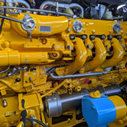
Replacing the shift solenoid on a 2022 RAM 1500 Pickup with a 5.7L V8 Hemi engine can be a bit complex, but I’ll break it down into simple steps. click here for more details on the download manual…..


    2022 Ram 1500 Denver, Littleton, Aurora, Parker, Colorado Springs, CO R7861 Billet Silver Metallic Clearcoat New 2022 Ram 1500 available in Denver Colorado at Brandon Dodge. Servicing the Littleton …

    What is eTorque? New Ram 1500 information A question I get a lot from new and existing Ram customers is in regards to the new eTorque technology. In this video I explain …

Before starting, make sure you have the necessary tools and parts, and always prioritize safety. Here’s a step-by-step guide:

### Tools and materials Needed:
1. **New Shift Solenoid**: Make sure it’s compatible with your RAM 1500.
2. **Basic Hand Tools**: Socket set, wrenches, and screwdrivers.
3. **Torque Wrench**: For tightening bolts to the correct specification.
4. **Jack and Jack Stands**: To lift the vehicle safely if needed.
5. **Drain Pan**: To catch any fluid that may spill.
6. **Gloves and Safety Glasses**: To protect yourself.

### Steps for Replacement:

#### Step 1: Safety First
– **Park the Vehicle**: Ensure the vehicle is on a flat surface.
– **Disconnect the Battery**: Remove the negative battery cable to prevent any electrical issues while you work.

#### Step 2: Access the Transmission
– **Lift the Vehicle**: If necessary, use a jack to lift the front of the truck and place it securely on jack stands.
– **Locate the Transmission**: The shift solenoid is inside the transmission. Depending on the model, you may need to remove some components or covers to access it.

#### Step 3: Drain Transmission Fluid
– **Position Drain Pan**: Place the drain pan under the transmission pan.
– **Remove the Transmission Pan**: Use a socket to remove the bolts holding the pan in place. Carefully lower the pan to allow the fluid to drain completely.

#### Step 4: Remove the Shift Solenoid
– **Locate the Shift Solenoid**: Inside the transmission, find the shift solenoid. It may be attached with a connector and a few bolts.
– **Disconnect the Electrical Connector**: Gently pull the connector off the solenoid.
– **Remove the Bolts**: Use the socket to unscrew the bolts holding the solenoid in place. Be careful not to drop any bolts into the transmission.

#### Step 5: Install the New Shift Solenoid
– **Position the New Solenoid**: Place the new shift solenoid in the same position as the old one.
– **Secure it with Bolts**: Hand-tighten the bolts first, then use a torque wrench to tighten them to the manufacturer’s specifications.
– **Reconnect the Electrical Connector**: Ensure it clicks into place securely.

#### Step 6: Reassemble the Transmission
– **Reattach the Transmission Pan**: Clean the surface of the pan and install a new gasket if necessary. Secure it with the bolts and tighten them evenly.
– **Add Transmission Fluid**: Pour the appropriate type of transmission fluid through the dipstick tube or fill port. check your owner’s manual for specifications.

#### Step 7: final Checks
– **Reconnect the Battery**: Put the negative battery cable back on.
– **Start the Engine**: Let it run for a few minutesdownload 2022 RAM 1500 Pickup 5.7L V8 Hemi MDS VVT ETorque workshop manual and check for any leaks.
– **Test Drive**: Take the vehicle for a short drive to ensure the solenoid is functioning properly.

### Conclusion
Replacing the shift solenoid can be a challenging task, but with patience and careful attention to detail, it can be done successfully. If you’re unsure at any point, it’s always a good idea to consult a professional mechanic. Always refer to your vehicle’s service manual for specific instructions and torque specifications.
A leaf spring is a type of suspension component commonly used in vehicles, particularly in trucks, vans, and some passenger cars. It consists of several layers, or “leaves,” of flat, elongated spring steel that are stacked together in a manner that creates a curved shape. This design allows the leaf spring to flex under load, absorbing shocks and impacts from the road while supporting the vehicle’s weight. The primary purpose of leaf springs is to provide a balance between ride comfort and load-carrying capacity, making them ideal for heavy-duty applications.

Leaf springs are typically mounted on the vehicle’s axle and connect to the frame. When a load is applied, the leaves compress and flex, distributing the weight evenly across the suspension system. This helps maintain proper vehicle height and stability, enhancing handling and safety. Leaf springs also have a natural damping effect, which reduces the impact of bumps and rough terrain on the vehicle’s occupants.

One of the advantages of leaf springs is their simplicity and robustness, which makes them relatively easy to manufacture and maintain. They are also cost-effective compared to more complex suspension systems. However, they can be less effective in providing a smooth ride compared to modern coil spring systems, especially in passenger vehicles. despite this, leaf springs remain a popular choice for applications requiring high load capacity and durability, such as in commercial vehicles and off-road applications.

Download 2006 Nissan Maxima Service & Repair Manual Software –

service manual
Repairing a dual-clutch transmission (DCT) on a Nissan Maxima is a complex process that requires a good understanding of automotive mechanics and access to specialized tools. click here for more details on the download manual…..


    Radiator replacement 2014 Maxima

    2022 Nissan Maxima Muffler Delete

Below is a detailed guide outlining the tools needed and the general steps involved in the repair process. This is a high-level overview and may not cover every specific detail for your model year, so please consult a service manual for exact specifications.

### tools Needed:

– **Socket Set**:
– A complete set of metric sockets (including deep sockets) to remove various bolts and fasteners.
– Ratchet and extension bars for reaching tight spaces.

– **Torque Wrench**:
– A click-type or beam-type torque wrench to ensure that bolts are tightened to the manufacturer’s specified torque settings.

– **Screwdriver Set**:
– Flat-head and Phillips screwdrivers for removing covers and small components.

– **Pliers**:
– Needle-nose and regular pliers for gripping and pulling small parts.

– **Transmission Fluid Pump**:
– To refill the transmission fluid accurately after repairs.

– **Transmission Jack**:
– A specialized jack to safely support and lower the transmission during removal and installation.

– **Oil Catch Pan**:
– To catch any fluid that may leak out during the repair process.

– **O-ring and Gasket Kit**:
– Replacement seals and gaskets to prevent leaks after reassembly.

– **Diagnostic Scanner**:
– An OBD-II scanner to check for error codes and perform system diagnostics.

– **Shop Manual/Service Manual**:
– A detailed guide specific to the Nissan Maxima that includes repair procedures, specifications, and torque settings.

– **Work Light**:
– To illuminate the work area for better visibility.

### General Steps for Dual-Clutch Transmission Repair:

– **Preparation**:
– Gather all tools and materials needed before starting the repair.
– Ensure you have a clean workspace and proper safety equipment (gloves, goggles).

– **Disconnect Battery**:
– Disconnect the negative terminal of the battery to prevent electrical shorts during the repair.

– **Lift the Vehicle**:
– Use a hydraulic jack to lift the front of the vehicle and secure it on jack stands for safety.

– **Drain Transmission Fluid**:
– Place an oil catch pan under the transmission and remove the drain plug to allow the fluid to drain completely.

– **Remove Underbody Covers**:
– Use the socket set and screwdrivers to remove any underbody panels or covers that obstruct access to the transmission.

– **Disconnect Transmission Components**:
– Detach the drive shafts, electrical connectors, and any other components that connect to the transmission.
– Label wires and components for easy reinstallation.

– **Remove the Transmission**:
– Use the transmission jack to support the transmission, then remove the mounting bolts.
– Carefully lower the transmission from the vehicle.

– **Disassemble the Transmission**:
– Following the service manual, carefully disassemble the transmission. Take note of the order of parts for reassembly.
– Inspect components such as clutches, gears,download Nissan Maxima workshop manual and actuators for wear or damage.

– **Replace Worn Components**:
– Replace any damaged or worn components using the O-ring and gasket kit for seals.
– Ensure that all new parts meet OEM specifications.

– **Reassemble the Transmission**:
– Carefully reassemble the transmission in the reverse order of disassembly, ensuring all components are correctly positioned and torqued to specification.

– **Reinstall the Transmission**:
– Use the transmission jack to lift the transmission back into place. Reattach mounting bolts and ensure everything is secure.

– **Reconnect Components**:
– Reattach all drive shafts, electrical connectors, and any other components that were removed.

– **Refill Transmission Fluid**:
– Use the transmission fluid pump to refill the transmission with the recommended fluid type, ensuring to check the level per the manufacturer’s specifications.

– **Reconnect Battery**:
– Reattach the negative terminal of the battery.

– **Test Drive**:
– Start the vehicle and check for any leaks or abnormal noises. Perform a test drive to ensure the transmission operates smoothly.

– **Run Diagnostics**:
– Use the diagnostic scanner to check for any error codes and confirm that the transmission control module (TCM) is functioning properly.

### Final Notes:

– Always consult the specific service manual for your Nissan Maxima model year for detailed instructions and specifications.
– If you are not experienced in transmission repair, consider seeking professional assistance to avoid potential damage to the vehicle.
A tire pressure sensor is a crucial component of a vehicle’s tire pressure monitoring system (TPMS), designed to monitor and report the air pressure within the tires. These sensors play a vital role in ensuring vehicle safety and performance by helping to maintain optimal tire pressure, which is essential for fuel efficiency, handling, and overall driving safety.

There are two primary types of tire pressure sensors: direct and indirect. Direct tire pressure sensors are located inside the tire, typically attached to the valve stem. They use a small battery-powered transmitter to send real-time data about tire pressure to the vehicle’s onboard computer system. Indirect tire pressure sensors, on the other hand, do not measure pressure directly. Instead, they rely on the vehicle’s anti-lock braking system (ABS) to monitor wheel rotation speed. If a tire is under-inflated, it has a smaller diameter and rotates faster than properly inflated tires, triggering a warning light on the dashboard.

The functionality of tire pressure sensors is critical, as under-inflated tires can lead to increased tire wear, decreased fuel efficiency, and a higher risk of tire blowouts. Many modern vehicles come equipped with TPMS as a standard feature, with warnings activated when tire pressure drops below a specified threshold. Regularly checking tire pressure and ensuring that sensors are functioning correctly is essential for safe vehicle operation and optimal driving performance.

Download 2012 Volkswagen Golf Mk6 R 5 Doors Download Service & Repair Manual –

bookshop
Installing a suspension lift kit on a Volkswagen Golf Mk6 R (5-door) involves several steps and requires a good understanding of automotive mechanics. click here for more details on the download manual…..


    VW Golf R MK6 2.0 TSI DSG 270 PS Top Speed Drive German Autobahn No Speed Limit POV 2010 VW Golf 6 R 2.0 TSI DSG 4Motion 199 kW/270 PS 350 Nm 1984 ccm 1521 kg 200.000 km No Speedlimit Topspeed Drive …

    VW Golf R MK6 with 2-STEP ANTI-LAG!! – INSANE Flames & Bangs @ Wörthersee *MUST SEE* Facebook: http://www.fb.com/NM2255 – Instagram http://www.instagram.com/nicknm2255/ ○ Now this is the loudest 2 Step I have …

Below is a detailed guide, along with descriptions of each component involved in the installation process.

### Components of a Suspension Lift Kit

1. **Lift Spacers**: These are used to increase the height of the vehicle. They are typically made from polyurethane or aluminum and are placed above the strut assembly.

2. **Extended Struts/Shocks**: If the lift is significant, you may need longer struts or shocks to maintain proper suspension travel and geometry.

3. **Control Arm Drop Brackets**: These are used to lower the control arms to maintain proper angles for suspension components.

4. **Alignment Kit**: Camber and toe bolts may be needed to adjust the alignment after the lift is installed.

5. **Hardware (Bolts, Nuts, Washers)**: New hardware may be included in the kit to ensure a secure fit.

6. **Instructions Manual**: most kits come with installation instructions specific to the vehicle.

### Tools Required

– Socket set (metric)
– Wrenches (metric)
– Torque wrench
– Jack and jack stands
– Spring compressor (if needed)
– Screwdrivers
– Pliers
– Hammer
– Safety glasses
– Gloves

### Preparation Steps

1. **Safety First**: Ensure you are working in a well-ventilated area. Wear safety glasses and gloves.

2. **Gather Tools and Components**: Have all tools and lift kit components ready for the installation.

3. **Lift the Vehicle**: Use a jack to lift the front of the car and secure it on jack stands. Ensure the vehicle is stable before proceeding.

4. **Remove the Wheels**: Use a socket wrench to remove the lug nuts and take off the wheels, exposing the suspension components.

### Installation Steps

#### Front Suspension

1. **Remove the Strut**:
– Locate the top strut nuts under the hood (usually three per strut).
– Remove these nuts with a socket wrench.
– Underneath the vehicle, remove the bolts that secure the strut to the steering knuckle.
– Carefully pull the strut out of the wheel well.

2. **Install Lift Spacers**:
– If using lift spacers, place them on top of the strut assembly.
– Align the spacer holes with the strut holes.

3. **Reinstall the Strut**:
– Insert the strut back into the wheel well, securing it to the steering knuckle first.
– Tighten the bolts to the manufacturer’s specified torque.

4. **Secure the Top of the Strut**:
go back to the engine bay and secure the top of the strut with the nuts you previously removed.
– Tighten them to the specified torque.

5. **Repeat for the other Side**: Follow the same procedure for the other front strut.

#### Rear Suspension

1. **Remove Rear Shocks**:
– Access the rear shocks by removing any necessary panels or covers.
– Remove the top nut securing the shock and then the bottom bolt.
– Pull out the shock absorber.

2. **Install Lift Kit Components**:
– Depending on the kit, you may need to install lift spacers or new extended shocks.
– If using spacers, install them above the shock mount.

3. **Reinstall Rear Shocks**:
– Insert the new or modified shock into place.
– Secure the bottom bolt and the top nut. Ensure everything is tightened to the manufacturer’s specifications.

4. **Repeat for the other Side**: perform the same steps for the other rear shock absorber.

### Final Steps

1. **Reinstall the Wheels**: Place the wheels back onto the hubdownload Volkswagen Golf Mk6 R 5 Doors workshop manual and hand-tighten the lug nuts. Then, lower the vehicle from the jack stands and fully tighten the lug nuts in a star pattern.

2. **Check Alignment**: After installation, it’s crucial to have a professional alignment performed to ensure proper driving characteristics and tire wear.

3. **Test Drive**: Carefully take the vehicle for a test drive to ensure everything is functioning correctly and to check for any unusual noises or handling issues.

### Post-Installation

– After the installation, periodically check the bolts and hardware for any loosening.
– Monitor the vehicle’s handling and ride quality; adjustments may be necessary based on personal preference or driving conditions.

### Conclusion

Installing a suspension lift kit on a Volkswagen Golf Mk6 R can enhance its off-road capabilities and aesthetic appeal. However, it requires careful attention to detail and adherence to safety practices. Always refer to the specific instructions that come with your lift kit, as variations in design may require different steps or components.
The alternator bracket is a crucial component in the Automotive electrical system, serving as a supportive structure for the alternator, which generates electrical power for the vehicle. This bracket is typically made from durable materials such as steel or aluminum, designed to withstand the vibrations and stresses experienced during vehicle operation. Its primary function is to securely mount the alternator to the engine block, ensuring proper alignment and stability while allowing the alternator to operate efficiently.

The alternator itself is responsible for converting mechanical energy from the engine into electrical energy, which powers the vehicle’s electrical systems and charges the battery. The alternator bracket plays a vital role in this process by maintaining the alternator in the correct position for optimal belt alignment. This is essential because the alternator is driven by a serpentine belt connected to the engine’s crankshaft. If the alternator is misaligned due to a faulty or damaged bracket, it can lead to belt slippage, excessive wear, or even belt failure, which would compromise the electrical system’s functionality.

In addition to providing support, the alternator bracket often features multiple mounting points for securing the alternator and may include provisions for additional components, such as tensioners or idler pulleys. Over time, the bracket can be subject to wear and tear, leading to the need for replacement to maintain the overall efficiency and performance of the vehicle’s electrical system. Proper installation and maintenance of the alternator bracket are essential for ensuring the longevity and reliability of the alternator and the vehicle’s electrical components.

Download Komatsu 140E-5 Engine SAA6D140E-5 Service Repair Manual –

australian
Performing a transmission fluid flush on a Komatsu 140E-5 with an SAA6D140E-5 engine is a task that should be approached with care, especially for those with limited mechanical experience. click here for more details on the download manual…..


    ADJUSTMENT CROSSHEAD ENGINE KOMATSU SAA6D140E-5 UNIT HM400-3, D155-6, WA500-6 KOMATSU

    HAL HAL PENTING SAAT MENGGANTI POMPA SOLAR PADA UNIT D155A-6, HM400-3R, WA500-6_MUDAH DAN BENAR Salam alat berat Ganti supply pump eh malah muncul problem yang lain, ada error CA778 dan startnya juga lama baru bisa …

Below is a simplified step-by-step guide to help you understand the process. Before you start, make sure you have the necessary tools and materials, and consider consulting the owner’s manual for specific details Related to your machine.

### Tools and Materials Needed:
– New transmission fluid (check the owner’s manual for the correct type and amount)
– Transmission fluid filter (if applicable)
– Fluid evacuation pump or suction pump
– Wrenches and sockets (for removing bolts)
– Clean containers for old fluid
– Funnel for adding new fluid
– Rags or paper towels for cleanup
– Safety gloves and goggles

### Step-by-Step Guide:

1. **Safety First:**
– Ensure the machine is parked on a flat, stable surface.
– Turn off the engine and engage the parking brake.
– Wear safety gloves and goggles to protect yourself.

2. **Locate the Transmission Fluid Dipstick:**
– Open the engine compartment and locate the transmission fluid dipstick. It may be labeled and is usually found near the transmission.

3. **Check the Fluid Level:**
– Pull out the dipstick, wipe it clean with a rag, and reinsert it to check the fluid level. This will give you an idea of how much fluid is currently in the transmission.

4. **Prepare for Fluid Removal:**
– Place a clean container under the transmission to catch the old fluid.
– If your machine has a drain plug, use the appropriate wrench to remove it and allow the old fluid to drain completely. If not, you can use a fluid evacuation pump to remove the fluid through the dipstick tube.

5. **Remove the Old Filter (If Applicable):**
– If your transmission has a filter, locate it and remove it according to the manufacturer’s instructions. This may involve unscrewing it or unclipping it.

6. **Install the New Filter (If Applicable):**
– If you removed a filter, install the new One in its place. Make sure it’s secure and correctly oriented.

7. **Replace the Drain Plug:**
– Once all the old fluid has drained, replace the drain plug and tighten it securely.

8. **Add New Transmission Fluid:**
– Using a funnel, pour the new transmission fluid into the dipstick tube. Refer to your owner’s manual for the correct amount to add.

9. **Check the Fluid Level Again:**
– After adding the new fluid, wait a moment and then remove the dipstick again to check the fluid level. If it’s below the recommended level, add more fluid until it reaches the correct mark.

10. **Start the Engine:**
start the engine and let it run for a few minutes. This will help circulate the new fluid through the system.

11. **Check for Leaks:**
– After running the engine, check around the drain plugdownload Komatsu 140E 5 Engine SAA6D140E 5 workshop manual 
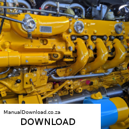
and filter (if applicable) for any signs of leaking fluid. If you see any leaks, you may need to tighten the plug or filter.

12. **Dispose of Old Fluid Properly:**
– Dispose of the old transmission fluid and any filters according to local regulations. Many auto parts stores or service stations accept used fluid for recycling.

### Final Thoughts:
Completing a transmission fluid flush can help maintain the performance and longevity of your Komatsu 140E-5. Always refer to the owner’s manual for specific instructions Related to your machine. If you are unsure about any part of the process, it might be wise to seek help from a professional mechanic.
A map light, also known as a reading light or interior light, is a small yet essential component found in many vehicles. Positioned typically on the overhead console or near the rearview mirror, the map light serves a practical purpose, providing illumination to help passengers read maps, locate items, or perform other tasks without disturbing the driver.

The design of a map light usually features a focused beam of light that can be adjusted or directed as needed. This adjustability allows occupants to illuminate specific areas, such as a map or a book, while minimizing glare and distraction to the driver. Many modern map lights utilize LED technology, which not only enhances energy efficiency but also prolongs the lifespan of the bulb compared to traditional incandescent options.

In addition to its functional aspects, the map light often contributes to the overall ambiance of the vehicle’s interior. It can be designed to match the vehicle’s aesthetic, offering various color temperatures, brightness levels, and switch types—such as toggle or touch-sensitive controls. Some vehicles even include features like a dimming function, allowing users to adjust the intensity of the light to suit their preferences.

Overall, the map light is a vital component that enhances the convenience and comfort of the driving experience, ensuring that passengers can easily access information or perform tasks without compromising safety.

Download Mitsubishi D04FD-TAA Diesel Engine* Factory Service / Repair/ Workshop Manual ! –

book store
Replacing the water pump on a Mitsubishi D04FD TAA engine involves several steps and requires a basic understanding of engine components, as well as the appropriate tools. click here for more details on the download manual…..


      Mitsubishi engine timing gear mark orders 153624 fg oder crank cap tourqe 300lbs connecting road cap tourqe 80lbs head bolt tourqe 120lbs valve clearance 40 inlet 60 …

    Below, I’ll provide a detailed guide to help you through the replacement process.

    ### Tools and Materials Needed:

    1. **Tools:**
    – Socket set (including extensions and universal joints)
    – Wrench set
    – Torque wrench
    – Screwdrivers (flat and Phillips)
    – Pliers
    gasket scraper (or razor blade)
    – Engine hoist (if necessary for access)
    – Timing belt tools (if applicable)
    – Drain pan
    – Shop towels or rags

    2. **Materials:**
    – New water pump (specific to Mitsubishi D04FD TAA)
    – New gasket or sealant (if applicable)
    – New coolant
    – New timing belt (if the water pump is driven by the timing belt and it’s due for replacement)

    ### Step-by-Step Replacement Procedure:

    #### 1. Preparation:

    – **Safety First**: Ensure the engine is cool. Disconnect the negative terminal of the battery to prevent any electrical issues during the repair.

    – **Drain Coolant**: Place a drain pan under the radiator and open the drain valve to drain the coolant. You can also remove the lower radiator hose for complete drainage.

    #### 2. Remove Components for Access:

    – **Access the Water Pump**: Depending on the engine layout, you may need to remove various components to access the water pump, such as:
    – **Timing Belt Cover**: If the water pump is behind the timing belt, remove the timing belt cover by unscrewing the bolts.
    – **Timing Belt**: If the water pump is driven by the timing belt, you will need to remove the belt. Use a tensioner tool to relieve tension before removing the belt.
    – **Accessory Belts**: Remove any Accessory belts that may obstruct access to the water pump. Loosen the tensioners and remove the belts from the pulleys.

    – **Other Components**: You might need to remove additional components such as the alternator, power steering pump, or engine mounts depending on the accessibility of the water pump.

    #### 3. Remove the Old Water Pump:

    – **Unscrew the Water Pump**: Locate the bolts securing the water pump to the engine block. Use the appropriate socket to remove these bolts. Keep track of the bolts as you will need them for the new pump.

    – **Remove the Water Pump**: Once the bolts are removed, gently pull the water pump away from the engine block. If it is stuck, carefully tap it with a rubber mallet to loosen it.

    – **Clean the Mounting Surface**: Use a gasket scraper or razor blade to remove any old gasket material from the engine block. Ensure that the surface is clean and free of debris to ensure a proper seal with the new pump.

    #### 4. Install the New Water Pump:

    – **Prepare the New Pump**: If your new water pump requires a gasket, apply gasket sealant if specified in the manufacturer’s instructions. Align the gasket with the pump if applicable.

    – **Position the New Pump**: Place the new water pump onto the engine block, ensuring it is aligned with the bolt holes.

    – **Install Bolts**: Hand-tighten the bolts into the water pump to secure it in place. Then, use a torque wrench to tighten the bolts to the manufacturer’s specified torque settings (consult the service manual for the exact torque values).

    #### 5. Reassemble Components:

    – **Reinstall the Timing Belt (if removed)**: If you removed the timing belt, ensure the timing marks are aligneddownload Mitsubishi D04FD TAA Engine workshop manual and then reinstall the belt. Adjust the tension according to the manufacturer’s specifications.

    – **Reattach Accessory Belts**: Reinstall any Accessory belts you removed. Ensure they are properly tensioned.

    – **Reinstall Any other Components**: Reattach any components you removed for access, such as the timing belt cover or engine mounts. Make sure all bolts are tightened to the specified torque.

    #### 6. Refill Coolant:

    – **Close Drain Valve**: If you drained the radiator, close the drain valve and reconnect the lower radiator hose.

    – **Refill Coolant**: Using a funnel, refill the cooling system with the appropriate type of coolant specified for your engine. Start with the radiator and then fill the overflow reservoir.

    #### 7. Test the System:

    – **Reconnect the Battery**: Reconnect the negative terminal of the battery.

    – **Start the Engine**: Start the engine and let it run for a few minutes. Check for leaks around the water pump area and ensure the engine reaches operating temperature.

    – **Check Coolant Levels**: After the engine has cooled down, check the coolant level again and top off if necessary.

    #### 8. Final Checks:

    – **Inspect for Leaks**: After running the engine, inspect the water pump and surrounding areas for any signs of leaking coolant.

    – **Dispose of Old Coolant**: Make sure to dispose of the old coolant and any waste materials according to local environmental regulations.

    ### Conclusion:

    Replacing the water pump on a Mitsubishi D04FD TAA engine is a straightforward process if you follow these steps carefully. Always refer to your vehicle’s service manual for specific details and torque specifications. If you are not confident in performing this replacement, consider seeking help from a professional mechanic.
    The turbo drain pipe is a crucial component in a turbocharged engine system. Its primary function is to facilitate the efficient removal of oil that has been used to lubricate the turbocharger. In a turbocharged engine, the turbocharger operates at high speeds and generates significant heat, necessitating proper lubrication to prevent wear and overheating. The turbo drain pipe is designed to collect the oil that drains from the turbocharger’s bearing housing after it has performed its lubricating function.

    Typically made from materials that can withstand high temperatures and resist oil degradation, the turbo drain pipe connects the turbocharger to the engine’s oil return system, allowing the oil to flow back into the engine’s sump. This return is essential for maintaining the correct oil levels, preventing oil starvation, and ensuring that the turbocharger operates smoothly and efficiently.

    Moreover, the design of the turbo drain pipe is engineered to minimize restrictions and ensure proper drainage, which is vital for the turbocharger’s performance. A well-functioning turbo drain pipe prevents oil from pooling in the turbocharger, which could lead to increased pressure and potential oil leaks or turbo failure. In summary, the turbo drain pipe plays a vital role in the longevity and efficiency of a turbocharged engine by ensuring optimal lubrication and preventing oil-related issues.

    Download OPEL OMEGA B 1994-2003 Workshop Service Repair Manual –

    workshop manual
    Replacing the heater core in an Opel Omega B can be a challenging task, especially for someone with little mechanical experience. click here for more details on the download manual…..


      Omega B 2.2 Tuning by RVD Garage

      Opel Omega B – Check For These Issues Before Buying What problems await you after buying a used Opel Omega B 1994 2003. The Opel Omega B is a large family car that was in …

    However, with patience and a clear understanding of the steps involved, you can accomplish this task. Here’s a simple guide to help you through the process.

    ### Tools and Materials Needed:
    – Screwdrivers (flathead and Phillips)
    – Socket set and ratchet
    – Pliers
    – A container to catch coolant
    – New heater core
    – New coolant
    – Towels or rags
    – Safety glasses and gloves

    ### Step-by-Step Guide:

    #### 1. **Preparation:**
    – **Safety First:** Ensure the car is parked on a level surface, turn off the ignition, and engage the parking brake. Wear safety glasses and gloves.
    – **Disconnect the Battery:** To avoid any electrical issues, disconnect the negative terminal of the battery.

    #### 2. **Drain the Coolant:**
    – Locate the radiator drain valve (usually at the bottom of the radiator) and place a container underneath it.
    – Open the valve to let the coolant drain out. Be careful as the coolant can be hot. Close the valve when finished.

    #### 3. **Remove Dashboard Components:**
    – **Remove the Center Console:** You may need to take out screws and clips holding the center console in place. Carefully lift it out and set it aside.
    – **Take Out the Dashboard:** This step can be complex. Look for screws and bolts securing the dashboard, especially around the instrument panel and glove compartment. Disconnect any electrical connectors as you go. Note where everything goes for reassembly.

    #### 4. **Access the Heater Core:**
    – Once the dashboard is removed, you should see the heater box, which contains the heater core.
    – Locate the heater core hoses at the firewall (the wall between the engine bay and the cabin).

    #### 5. **Disconnect the Heater Core Hoses:**
    – Use pliers to loosen the clamps on the heater core hoses and carefully slide them off. Be prepared for any remaining coolant to spill out, so have your container ready.

    #### 6. **Remove the Heater Core:**
    – Find any screws or bolts securing the heater core to the heater box. Remove them carefully.
    – Gently pull the heater core out of the heater box. Be cautious not to damage any surrounding components.

    #### 7. **Install the New Heater Core:**
    – Take your new heater core and insert it into the heater box, ensuring it fits snugly.
    – Reattach any screws or bolts you removed earlier to secure it in place.

    #### 8. **Reconnect the Heater Core Hoses:**
    – Slide the hoses back onto the heater core and tighten the clamps securely.

    #### 9. **Reassemble the Dashboard:**
    – Carefully put the dashboard back in place, reconnecting all electrical connectors and securing it with screws and bolts.
    – Reinstall the center console.

    #### 10. **Refill the Coolant:**
    – Open the radiator cap and refill the cooling system with new coolant. Make sure to check the owner’s manual for the correct type and mixture.
    – Start the engine and let it run for a few minutes, allowing the coolant to circulate. Check for leaks around the heater core hoses.

    #### 11. **Reconnect the Battery:**
    – Once everything is back in place, reconnect the negative terminal of the battery.

    ### Final Steps:
    – **Test the System:** Turn on the heater to ensure hot air is coming outdownload OPEL OMEGA B workshop manual and check for any leaks.
    – **Clean Up:** Dispose of any old coolant properly and clean up any spills.

    ### Important Tips:
    – Take pictures during disassembly to help with reassembly.
    – Be patient and don’t rush the process.
    – If you’re unsure about any step, consider consulting a professional mechanic or referring to a repair manual specific to the Opel Omega B.

    With careful attention to detail, you should be able to successfully replace the heater core in your Opel Omega B. Good luck!
    The heater control valve is a crucial component of a vehicle’s heating and cooling system, primarily responsible for regulating the flow of coolant from the engine to the vehicle’s heater core. Located typically within the engine bay or the dashboard area, this valve plays a vital role in maintaining the desired cabin temperature by controlling the amount of hot coolant that enters the heater core, which in turn heats the air that is blown into the passenger compartment.

    When the vehicle’s heating system is activated, the heater control valve opens to allow hot coolant to flow through the heater core. The heat from the coolant is then transferred to the air passing through the core, warming it before it is distributed throughout the cabin via the vehicle’s ventilation system. Conversely, when the heating system is turned off or adjusted to a cooler setting, the valve closes or restricts coolant flow, preventing hot coolant from entering the heater core, thereby maintaining a comfortable temperature for the occupants.

    Modern vehicles often utilize electronically controlled heater control valves that are integrated with the climate control system, allowing for more precise temperature management and improved fuel efficiency. A malfunctioning heater control valve can lead to insufficient cabin heating, overheating of the engine, or coolant leaks, making it essential for optimal vehicle performance and passenger comfort. Regular maintenance and timely inspections can help ensure the heater control valve functions correctly, contributing to a reliable and enjoyable driving experience.

    Download Chrysler Imperial 1990-1993 Workshop Repair Service Manual –

    owners manual
    Reconditioning a gearbox on a Chrysler Imperial involves a detailed and methodical approach. click here for more details on the download manual…..


      1960 Chrysler Imperial Classic Car Drive By Engine Sound Motor Muster Greenfield Village 2024

      Diagnosing The Chrysler Electronic Ignition System This video shows you how to diagnose a no/weak spark condition using common service tools.

    The gearbox, or transmission, is a critical component of the vehicle’s drivetrain, allowing the engine’s power to be effectively transferred to the wheels. This guide provides an overview of the process, the necessary tools, and the components involved in a typical gearbox reconditioning.

    ### Preparation

    #### Tools and Equipment Needed
    1. **Basic Hand Tools**: Wrenches, sockets, screwdrivers, pliers.
    2. **Specialized Tools**: Torque wrench, transmission jack, snap ring pliers, alignment tools, and seal pullers.
    3. **Cleaning Supplies**: Solvent, brushes, rags, and a parts washer.
    4. **Measuring Tools**: Calipers, micrometers, and dial gauges.
    5. **Replacement Parts**: Gaskets, seals, bearings, clutches, and other internal components as needed.

    #### Safety Equipment
    – Safety glasses
    – Gloves
    – Steel-toed boots

    ### Step-by-Step Process

    #### 1. Remove the Gearbox from the Vehicle
    – **Drain the Fluid**: Using a drain pan, remove the transmission fluid by draining it through the pan’s plug.
    – **Disconnect the Battery**: Remove the negative terminal to prevent electrical shorts.
    – **Remove Drive Shaft**: Loosen the bolts or clamps holding the driveshaft to the transmission and carefully slide it out.
    – **Detach Linkages**: Disconnect any shift linkages, throttle cables, or electrical connectors.
    – **Unbolt the Gearbox**: Remove the bolts securing the gearbox to the engine and any supporting brackets.
    – **Use a Transmission Jack**: Carefully lower the gearbox from the vehicle.

    #### 2. Disassemble the Gearbox
    – **Remove the Oil Pan**: Unbolt and take off the oil pan to access the internal components. clean the pan thoroughly.
    – **Inspect the Gasket**: check for wear and replace if necessary.
    – **Remove the Valve Body**: Detach the valve body, which controls the flow of fluid within the transmission.
    – **Take Out Clutch Packs**: Remove the clutch packs and inspect the friction materials. Replace any worn components.
    – **Remove the Planetary Gears**: Take out the planetary gear assembly, ensuring to note the arrangement for reassembly.
    – **Inspect All Components**: Examine gears, bearings, and seals for wear, scoring, or damage.

    #### 3. clean and Inspect Components
    – **Cleaning**: Use a solvent to clean all metal parts. A parts washer can be very effective.
    – **Inspection**: Measure components with calipers and micrometers. Look for:
    – Worn gears
    – Damaged bearings
    – Scorched clutch plates
    – Cracked or damaged housings

    #### 4. Replace Worn Components
    – **Ordering Parts**: Based on inspection, order any necessary replacement parts, including:
    – Gaskets and seals
    – Clutch packs
    – Bearings
    – Bands
    – **Install New Parts**: Carefully install new components, ensuring proper orientation and fit.

    #### 5. Reassemble the Gearbox
    – **Reinstall Clutch Packs**: Layer the new clutch packs as per the original arrangement.
    – **Reattach the Valve Body**: Ensure all bolts are torqued to specifications.
    – **Install the Planetary Gear Assembly**: Align and secure it in place.
    – **Replace the Oil Pump**: If removed, install the oil pump and ensure it operates smoothly.
    – **Reattach the Oil Pan**: clean the mating surfaces and apply a new gasket or sealant as necessary.

    #### 6. Final Checks
    – **Torque Specifications**: Use a torque wrench to ensure all bolts are tightened to the manufacturer’s specifications.
    – **Fluid Lines**: check all fluid lines for damage or blockages before reinstallation.
    – **Electrical Connections**: Ensure all electrical connections are secure.

    #### 7. Reinstallation in the Vehicle
    – **Position the Gearbox**: Use the transmission jack to raise the gearbox into position.
    – **Reconnect**: Bolt the gearbox to the enginedownload Chrysler Imperial workshop manual and Reconnect the drive shaft, linkages, and electrical connections.
    – **Refill Transmission Fluid**: Use the correct type of transmission fluid and fill to the appropriate level.

    #### 8. Testing
    – **Start the Engine**: check for leaks and listen for abnormal noises.
    – **Test Drive**: Take the vehicle for a short drive, checking for smooth shifting and proper operation.

    ### Conclusion
    Reconditioning a gearbox on a Chrysler Imperial requires careful attention to detail and a thorough understanding of the components involved. By following the above steps and using the appropriate tools, you can successfully restore the gearbox to optimal performance. Always refer to the specific service manual for your model for detailed technical specifications and torque settings.
    A coil spring is a vital component of a vehicle’s suspension system, designed to absorb shocks and maintain the vehicle’s ride height while ensuring stability and comfort. Typically made from high-carbon steel or other durable materials, coil springs are coiled into a helical shape, allowing them to compress and expand as the vehicle encounters various road conditions.

    Coil springs work by converting kinetic energy from bumps and irregularities in the road into potential energy, which is stored as the spring compresses. When the road surface returns to a smoother condition, the spring decompresses, releasing the stored energy and helping to maintain the vehicle’s balance. This process significantly enhances ride comfort by minimizing the impact of road imperfections on the vehicle’s chassis and occupants.

    In addition to shock absorption, coil springs play a crucial role in maintaining proper wheel alignment and ensuring that the tires remain in contact with the road, which is essential for effective handling and braking. They are often paired with shock absorbers, which help control the rate of spring compression and rebound, further enhancing vehicle stability.

    Coil springs are commonly used in various vehicle types, from sedans and SUVs to trucks and performance cars. Their design can vary significantly, with factors such as wire diameter, spring diameter, and number of coils influencing their characteristics. Overall, coil springs are indispensable for providing a smooth and controlled driving experience.

    Download 2003 Mercedes-Benz C-Class 240 (W203) OEM Download Service & Repair Manual Software –

    australian
    Certainly! click here for more details on the download manual…..


      start problem Mercedes w203 – bad ecu. This can be a fix for you if the ECU failed and need a sta… Start problem w203 mercedes. This can be a fix if your car ecu is not working well. This video shows a car with broken engine …

      Mercedes-Benz W203 C-Class Radiator Replacement The radiator on the W203 is not that difficult to replace, and there is just a small amount of stuff that you need to move out of the …

    Here’s a step-by-step guide for replacing the PCV (Positive Crankcase Ventilation) valve on a Mercedes-Benz C-Class 240 (W203) in reverse order:

    ### 8. **Reconnect Battery**
    – Reconnect the negative terminal of the battery.

    ### 7. **Reassemble Engine Cover**
    – Place the engine cover back onto the engine and secure it with any clips or screws you removed earlier.

    ### 6. **Reconnect Hoses and Electrical Connectors**
    – Reattach any hoses or electrical connectors that were disconnected during the process. Ensure they are secure and properly seated.

    ### 5. **Install New PCV Valve**
    – Position the new PCV valve into its designated location in the engine. Ensure it fits snugly and is properly oriented.
    – If applicable, replace any gaskets or O-rings to prevent leaks.

    ### 4. **Remove Old PCV Valve**
    – Carefully pull out the old PCV valve from its housing. You may need to gently wiggle it to free it from any clips or grommets.

    ### 3. **Access the PCV Valve**
    – Depending on the location, you may need to remove components obstructing access to the PCV valve. This can include intake hoses or other engine covers.
    – Use appropriate tools to remove any screws or clips.

    ### 2. **Prepare for Replacement**
    make sure the engine is cool and the vehicle is in a safe position (parked on a level surface, with the parking brake engaged).
    – Gather necessary tools and materials: new PCV valve, screwdrivers, pliers, and possibly a socket set.

    ### 1. **Disconnect Battery**
    – Disconnect the negative terminal of the battery to prevent any electrical shorts or issues while working on the vehicle.

    ### Additional Notes:
    – Always consult your vehicle’s service manual for specific torque specifications and procedures.
    – If you’re unsure about any step, consider seeking assistance from a professional mechanic.
    – Dispose of the old PCV valvedownload Mercedes Benz C Class 240 W203 OEM workshop manual and any other removed components properly.

    By following these steps in reverse order, you can successfully replace the PCV valve on your Mercedes-Benz C-Class 240 W203.
    The oil pressure sender, also known as the oil pressure sensor, is a crucial component in an automobile’s engine monitoring system. Its primary function is to monitor the oil pressure within the engine and relay that information to the vehicle’s dashboard, typically through a gauge or warning light. This component plays a vital role in ensuring the engine operates efficiently and safely.

    The oil pressure sender is usually located near the Oil filter or on the engine block, where it can accurately measure the oil pressure generated by the oil pump as it circulates oil throughout the engine. The sender operates on the principle of converting mechanical pressure into an electrical signal. When the oil pressure is within the normal range, the sender transmits a corresponding signal to the gauge, indicating a healthy operating condition. If the oil pressure falls below a certain threshold, which can indicate low oil levels or a failing oil pump, the sender activates a warning light on the dashboard, alerting the driver to a potentially serious issue.

    Maintaining proper oil pressure is essential for the longevity and performance of an engine. Insufficient oil pressure can lead to increased friction, overheating, and ultimately engine damage. Therefore, the oil pressure sender is integral to the vehicle’s overall health, providing real-time feedback that helps drivers take necessary actions to avoid costly repairs. Regular checks and timely replacements of this component can significantly contribute to the maintenance of an engine’s efficiency and reliability.

    Download 1997 Jeep Cherokee XJ Service Repair Manual –

    australian
    If the check engine light on your Jeep Cherokee XJ is illuminated, it means that the vehicle’s onboard computer has detected a problem. click here for more details on the download manual…..


      Jeep Cherokee XJ – Rough Country drive shaft unboxing ordered the driveshaft for the XJ http://www.roughcountry.com/rear-cv-drive-shaft-jeep-xj-5076-1.html.

      Jeep Cherokee: Transfer Case Options & How to Use 4wd Correctly ['84-'01 XJ] Transfer case options, differences, and how to properly use 4 wheel drive in the 1984-2001 Jeep Cherokee. In all model years, …

    Here’s a simple guide on how to check what might be causing the light to come on, even if you don’t have much mechanical experience:

    ### Step 1: Safety First
    1. **Park Safely:** Make sure your Jeep is parked on a level surface, away from traffic.
    2. **Turn Off the Engine:** Before you start checking anything, turn off the engine and remove the key from the ignition.

    ### Step 2: Check for Obvious Issues
    1. **Gas Cap:** A loose or damaged gas cap can trigger the check engine light. Check to see if it’s tight and in good condition. If it’s loose, tighten it and drive for a bit to see if the light goes off.
    2. **Look Under the Hood:** Check for any obvious signs of trouble, like loose wires or hoses, leaks, or anything that looks out of place.

    ### Step 3: Use an OBD-II Scanner
    1. **Get an OBD-II Scanner:** This is a small device that you can buy or borrow from an auto parts store. Many stores also offer free scanning services.
    2. **Locate the OBD-II Port:** In the Jeep Cherokee XJ, the OBD-II port is usually located under the dashboard, near the steering column.
    3. **Plug in the Scanner:** Insert the scanner’s connector into the OBD-II port.
    4. **Turn on the Ignition:** Without starting the engine, turn the key to the “On” position (the second click).
    5. **Read the Codes:** Follow the instructions on the scanner to read the trouble codes. These codes will give you an idea of what’s causing the check engine light to be on.

    ### Step 4: Understanding the Codes
    1. **Look Up the Codes:** Write down the codes displayed on the scanner and refer to the user manual or search online for their meanings.
    2. **Common Issues:** Some common causes for a check engine light include problems with the oxygen sensor, mass airflow sensor, spark plugs, or catalytic converter.

    ### Step 5: Fix the Problem
    1. **Simple Fixes:** If the issue is something simple (like a loose gas cap), you can fix it yourself.
    2. **Professional Help:** For more complex issues, it may be best to consult a mechanic. Bring the codes you retrieved to help them diagnose the problem more quickly.

    ### Step 6: Resetting the Check Engine Light
    1. **After Fixing:** If you’ve resolved the issue, you can reset the check engine light. This can often be done by disconnecting the battery for a few minutes or using the OBD-II scanner’s reset function.
    2. **Drive the Jeep:** Sometimes, it takes a little time for the system to recognize the fix. Drive your Jeep for a short whiledownload Jeep Cherokee XJ workshop manual and see if the light stays off.

    ### Conclusion
    Remember, the check engine light is an important indicator that something may need attention. It’s always best to address it sooner rather than later to avoid bigger problems down the road. If you’re unsure about any steps, don’t hesitate to ask a friend or a professional for help!
    The radiator is a crucial component of a vehicle’s cooling system, designed to regulate the engine’s temperature and prevent overheating. It operates by dissipating heat generated during the combustion process, ensuring that the engine operates within an optimal temperature range. The radiator is typically made of metal, often aluminum or copper, and consists of a series of thin tubes and fins that enhance its ability to transfer heat.

    When the engine runs, coolant circulates through the engine block, absorbing heat. This heated coolant then flows into the radiator, where it passes through the tubes. As air flows over the surface of the radiator, either from the vehicle’s movement or through the action of a fan, heat is transferred from the coolant to the air. This process cools the coolant before it returns to the engine to absorb more heat, thus creating a continuous loop.

    Maintaining the radiator is vital for the overall health of the vehicle. Over time, radiators can become clogged with debris or develop leaks, which can lead to engine overheating and potential damage. Regular inspections, coolant changes, and addressing any leaks promptly can help ensure the radiator functions effectively. In summary, the radiator plays a vital role in engine performance and longevity, making it an essential component of any vehicle’s cooling system.

    Download 1979-1997 Ford Mustang Workshop Service Repair Manual –

    book shop
    Replacing the transmission pan gasket on a Ford Mustang involves several steps and requires specific tools and materials. click here for more details on the download manual…..


      The Most Common Transmission Failure On The Ford Explorer Mustang 5R55S & How To Fix It To clarify this is a permanent fix in such that even a new case or sleeving the case will wear out in time same as the o-rings on …

      Building a Mustang GT: 10 Hidden Things You Didn’t Know Start working on your cars at home, all the tools to get started-http://bit.ly/toolsfromcam Vlogs, Extras, Life, RC Car Videos on Cam …

    Here’s a detailed guide:

    ### Tools and Materials Needed:

    – **Socket Set**: A comprehensive socket set with metric and standard sizes will be necessary to remove the bolts securing the transmission pan.

    – **Ratchet and Extensions**: A ratchet for turning the sockets and extensions to reach bolts that may be difficult to access.

    – **Torque Wrench**: To ensure that bolts are tightened to the manufacturer’s specified torque settings when reassembling.

    – **Gasket Scraper**: A specialized scraper or a putty knife to remove the old gasket material from the pan and transmission surface without damaging them.

    – **Clean Rags**: For cleaning surfaces and removing any excess fluid.

    – **Transmission Fluid**: New fluid is required to refill the transmission after the gasket replacement.

    – **New Transmission Pan Gasket**: make sure to purchase a gasket that is compatible with your specific Mustang model year and transmission type.

    – **Oil Drain Pan**: To catch any transmission fluid that may leak out when removing the transmission pan.

    – **Safety Glasses and Gloves**: For personal protection during the process.

    ### Step-by-Step Instructions:

    – **Preparation**:
    – Ensure the vehicle is parked on a flat, stable surface and secure it with wheel chocks.
    – Raise the Mustang using a hydraulic jack and support it with jack stands to access the underside safely.

    – **Drain the Transmission Fluid**:
    – Place the oil drain pan under the transmission pan.
    – Remove the transmission pan bolts, starting from the rear and moving forward, leaving a few bolts loosely fastened at the front to control fluid flow.
    – Once most fluid has drained, remove the remaining bolts and carefully lower the pan.

    – **Remove the Old Gasket**:
    – Use the gasket scraper to carefully remove the old gasket material from both the transmission pan and the transmission surface.
    – Be cautious not to scratch or damage the mating surfaces.
    – Clean the surfaces thoroughly with clean rags to ensure no debris or old gasket material remains.

    – **Inspect the Transmission Pan**:
    – Check the transmission pan for any dents, cracks, or damage that might need repair or replacement.
    – Clean the inside of the pan to remove any metal shavings or debris.

    – **Install the New Gasket**:
    – Place the new gasket onto the transmission pan, ensuring it is aligned properly with the bolt holes.
    – If the gasket is adhesive, press it into place; otherwise, just position it correctly.

    – **Reattach the Transmission Pan**:
    – Lift the transmission pan back into positiondownload Ford Mustang workshop manual and align it with the bolt holes.
    – Start by hand-tightening a few bolts at each corner to secure the pan in place.
    – Use the torque wrench to tighten the bolts in a crisscross pattern to the manufacturer’s specified torque setting to ensure even pressure on the gasket.

    – **Refill Transmission Fluid**:
    – Locate the transmission dipstick tube or fill hole, and use a funnel to add new transmission fluid.
    – Consult the owner’s manual for the correct type and amount of transmission fluid required.

    – **Check for Leaks**:
    – Start the engine and let it run for a few minutes.
    – Shift through all gears to circulate the new fluid.
    – Check under the vehicle for any signs of leaks around the transmission pan.
    – If no leaks are found, turn off the engine and check the fluid level with the dipstick, adding more fluid if necessary.

    – **Final Steps**:
    – Lower the vehicle back to the ground.
    – Dispose of the old fluid and gasket responsibly according to local regulations.

    This comprehensive guide should help you successfully replace the transmission pan gasket on your Ford Mustang. Always refer to the specific service manual for your vehicle for any additional details or specifications.
    The driveshaft is a crucial component in the drivetrain of a vehicle, serving as a mechanical link that transmits power from the engine to the wheels. Typically cylindrical in shape, it is designed to withstand high torque and rotational forces while allowing for flexibility and movement. The driveshaft connects the transmission to the differential, facilitating the transfer of engine power to the axle, which in turn drives the wheels.

    In most vehicles, especially those with rear-wheel drive (RWD) or all-wheel drive (AWD), the driveshaft is an essential part of the power delivery system. It is usually made from strong materials such as steel or aluminum to endure the stresses of operation. The length of the driveshaft can vary based on the vehicle’s design, and it may consist of one or more sections, known as “splined” sections, which allow for some degree of flexibility, accommodating the movement of the suspension system.

    Driveshafts often incorporate universal joints (U-joints) or constant velocity (CV) joints, which enable them to transmit power at varying angles and compensate for changes in alignment due to vehicle dynamics. Proper maintenance of the driveshaft is vital, as wear and tear can lead to vibrations, noise, or even catastrophic failure, impacting vehicle performance and safety. Understanding the driveshaft’s role enhances one’s appreciation for the complex engineering that enables smooth and efficient vehicle operation.