Download Subaru Legacy 2004 Workshop Service Repair Manual –

service manual
Repairing the suspension strut tower on a Subaru Legacy involves several steps and a number of components. click here for more details on the download manual…..


    2022 Subaru Legacy | Review & Road Test For the latest Subaru Legacy pricing and information: https://www.kbb.com/subaru/legacy/ This is the 7th-generation Subaru …

    How to Check a Used Subaru Legacy Before Buying (2015-2019) Used Subaru Legacy (6th Gen) Review & Test-Drive Tips (2015-2019) In this video, we look at some advice and tips to consider …

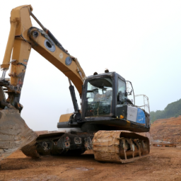
The strut tower is part of the unibody structure of the car, typically located at the front and rear where the strut assembly connects to the body. If the strut tower is damaged or rusted, it may need repair to ensure proper suspension function and vehicle safety. Below is a detailed guide on how to perform this repair.

### Tools and Materials Needed:
– **Tools:**
socket set (including ratchet and extensions)
– Wrenches (including torque wrench)
– Screwdrivers (flathead and Phillips)
– Pry bar
– Hammer
– Cutting tool (grinder or saw)
– Drill with metal bits
– Spot weld cutter (if needed)
– Sockets for strut assembly bolts
– Jack and jack stands
safety glasses
– Gloves

– **Materials:**
– Replacement strut tower (if severely damaged)
– Sheet metal (if fabricating)
– Welding rod or MIG wire (if welding)
– Rust-proof paint
– Primer
– Body filler (if needed)

### Steps for Suspension Strut Tower Repair:

#### 1. **Preparation**
– **Safety First:** Park the vehicle on a level surface and engage the parking brake. Wear safety glasses and gloves.
– **Disconnect the Battery:** Disconnect the negative terminal of the battery to prevent any electrical issues.
– **Remove the Wheel:** Use a jack to lift the front or rear of the vehicle (depending on the strut tower being repaired) and secure it with jack stands. Remove the wheel using a lug wrench.

#### 2. **Access the Strut Tower**
– **Remove Components:** Depending on the access needed, you may need to remove components like the fender liner, air intake, or other obstructions that cover the strut tower. Use the appropriate tools to unbolt and remove these parts carefully.

#### 3. **Inspect the Strut Tower**
– **Assess Damage:** Examine the strut tower for rust, cracks, or physical damage. If it’s only surface rust, it may just need to be cleaned and treated. If the damage is severe (such as a large hole or structural weakness), you will need to replace the tower or fabricate a repair panel.

#### 4. **Preparing for Repair**
– **Cut Out Damaged Area:** If the strut tower is rusted or damaged beyond repair, use a cutting tool to remove the affected section. Be cautious not to damage surrounding areas.
– **Fabricate a Patch Panel (if necessary):** If you’re crafting a new section, measure the dimensions of the cut-out area. Cut a piece of sheet metal to size, ensuring it overlaps onto solid metal.

#### 5. **Welding the New Section**
– **Position the New Panel:** place the fabricated patch into the strut tower area. Clamp it in place to prevent movement during welding.
– **Weld the Patch:** Use a MIG welder or stick welder to attach the new section to the strut tower. Ensure proper penetration and coverage for a strong bond. Make sure to wear proper protective gear and follow safety protocols while welding.

#### 6. **Reinforce the Structure**
– **Reinforcement (if required):** If the strut tower was severely compromised, consider adding additional support or bracing. This can be done using additional metal brackets or plates welded in place.

#### 7. **Finishing Touches**
– **Cleandownload Subaru Legacy workshop manual and Treat:** Grind down any rough welds for a smooth finish. Treat the area with rust-inhibiting primer and paint to prevent future corrosion. Allow it to dry completely.
– **Body Filler (if needed):** If there are imperfections in the surface, apply body filler to smooth out any rough spots. Sand it down to a smooth finish.

#### 8. **Reassembly**
– **Reinstall Components:** Reattach any components that were removed earlier (e.g., fender liners, air intake).
– **Install the Strut Assembly:** If the strut assembly was removed, reinstall it by following the reverse order of disassembly. Ensure all bolts are torqued to the manufacturer’s specifications.

#### 9. **Final Checks**
– **Reconnect the Battery:** Reconnect the negative terminal of the battery.
– **Reinstall the Wheel:** Put the wheel back on and lower the vehicle to the ground. Tighten the lug nuts to the proper torque specification.
– **Test Drive:** Take the vehicle for a test drive to ensure proper handling and check for any unusual noises or handling characteristics.

### Conclusion
Repairing the suspension strut tower on a Subaru Legacy is a detailed process that requires mechanical skill and safety awareness. Make sure to follow all safety procedures and consult the vehicle’s service manual for specific torque specifications and component locations. If you’re unsure about any part of the process, consider consulting a professional mechanic to ensure the repair is done correctly.
The trunk emblem, often referred to as a trunk badge or logo, is a decorative and functional component typically located on the rear of a vehicle, specifically on the trunk lid or tailgate. This emblem serves multiple purposes, both aesthetic and practical. Primarily, it is designed to showcase the brand identity of the vehicle manufacturer, often featuring the company’s logo, name, or model designation. This branding helps to establish a vehicle’s lineage and can evoke a sense of prestige or heritage associated with the brand.

In addition to branding, the trunk emblem can also convey specific information about the vehicle. For instance, it may indicate the model name, engine type, or trim level, providing potential buyers or enthusiasts with quick recognition of the vehicle’s specifications. This is particularly important in a market filled with diverse models and variations.

From a design perspective, trunk emblems can vary significantly in size, shape, and material, ranging from simple plastic badges to more elaborate metal designs with chrome finishes. The design of the emblem often reflects the overall styling of the vehicle, enhancing its visual appeal. Furthermore, trunk emblems are usually engineered to withstand various weather conditions, ensuring durability and longevity, which is crucial for maintaining the car’s aesthetic integrity over time. Overall, the trunk emblem is a small yet significant component that plays a vital role in the vehicle’s identity and presentation.

Download Hyundai R250LC-3 Crawler Excavator Workshop Service Manual –

stores
Replacing the shift cable on a Hyundai R250LC-3 Crawler Excavator involves several steps, and it is important to follow a methodical approach to ensure the job is done correctly. click here for more details on the download manual…..


    Water Tank Radiator ASS'Y 11M9-45010 11M945010 for Hyundai Excavator R55-9 R60-9S R55W-9 R60W… Water Tank Radiator ASS’Y 11M9-45010 11M945010 for Hyundai Excavator R55-9 R60-9S R55W-9 R60W-9S From …

    3863451 CONN-OIL SUCTION for Hyundai excavator 3863451 CONN-OIL SUCTION for Hyundai excavator R140LC-9S, R160LC-9S, R170W-3, R180LC-3, R200NLC-3, R200W-3, …

Below is a detailed guide outlining the components, tools, and step-by-step instructions for replacing the shift cable.

### components Involved
1. **Shift Cable**: This is the main component that connects the shift lever to the transmission control mechanism.
2. **Shift Lever**: Located in the operator’s cabin, this lever is used to change the gear.
3. **Transmission Control Mechanism**: This device receives the input from the shift cable and controls the gear shifting in the transmission.
4. **Cable Clips/Retainers**: These are used to secure the shift cable in place.
5. **Adjustment Nut**: This may be used for adjusting the tension in the shift cable.
6. **Protective Sleeves**: Some cables may have protective sleeves to prevent wear and tear.

### Tools Required
– **Socket Set**: For removing bolts and nuts.
– **Wrench Set**: For securing and loosening nuts.
– **Pliers**: For pulling and securing clips.
– **Screwdrivers**: For removing any covers or retaining screws.
– **Cable Routing Tool**: Optional, for guiding the new cable into place.
– **Safety Gear**: Gloves and goggles for personal protection.

### Step-by-Step Instructions

#### Step 1: Safety First
– Ensure the excavator is on a flat surface.
– Engage the parking brake.
– Disconnect the battery to prevent any accidental starts.

#### Step 2: Access the Shift Cable
– Open the operator’s cabin or access panel to reach the shift lever.
– If necessary, remove any covers or panels that obstruct access to the shift cable and lever.

#### Step 3: Disconnect the Old Shift Cable
– Locate the connection point where the shift cable attaches to the shift lever.
– Use a wrench to loosen the adjustment nut (if applicable) and disconnect the cable from the lever.
– Move to the transmission control mechanism and locate where the other end of the shift cable connects.
– Again, use a wrench to remove any bolts or clips securing the cable.
– Carefully pull out the old shift cable from its routing path.

#### Step 4: Prepare for Installation
– Inspect the mounting points and ensure there are no obstructions or debris that could interfere with the new installation.
– Compare the old shift cable with the new one to ensure they are identical in length and fittings.

#### Step 5: Install the New Shift Cable
– Route the new shift cable through the same path as the old cable. Use a cable routing tool if necessary for guidance.
– Secure the cable at the transmission control mechanism first by connecting it to its designated point and tightening any bolts or clips.
– Move to the shift lever and connect the other end of the cable. adjust the cable length as needed using the adjustment nut.
– Ensure that the cable is not too loose or too tight.

#### Step 6: Test the Installation
– Before reassembling any covers or panels, test the shift lever by moving it through its range of motion.
– Check that the cable moves smoothly without any binding or excessive slack.
– If the cable does not operate smoothly, recheck the routingdownload Hyundai R250LC 3 Crawler Excavator workshop manual and adjustments.

#### Step 7: Secure Everything
– Once satisfied that the shift cable is functioning correctly, secure any cable clips or retainers.
– Replace any covers or panels that were removed during the process.
– Reconnect the battery.

#### Step 8: Final Testing
– Start the excavator and test the shift lever in various gears to ensure the shift cable is correctly installed and operating as intended.

### Conclusion
Replacing the shift cable on a Hyundai R250LC-3 Crawler Excavator requires careful attention to detail and methodical execution. By following these steps, you can successfully replace the shift cable and restore the proper functioning of the gear-shifting mechanism. Always refer to the manufacturer’s service manual for specific details related to your model, as there may be slight variations in the process or components.
Polish, in the context of Automotive care, refers to a type of product used to enhance and maintain the appearance of a vehicle’s exterior surfaces. Specifically, car polish is designed to improve the shine and luster of the paint while also providing a level of protection against environmental factors. It typically contains fine abrasives that help to remove minor imperfections such as swirl marks, light scratches, and oxidation, thereby restoring the car’s original finish.

The process of polishing a car usually involves applying the polish using a soft cloth or a polishing machine, working it into the surface in circular motions. As the polish is worked into the paint, the abrasives gently cut into the clear coat, smoothing out imperfections and allowing the underlying color to shine through more vividly. This not only enhances the aesthetic appeal of the vehicle but can also contribute to its resale value by maintaining a well-kept appearance.

In addition to aesthetic benefits, many modern polishes also contain protective agents, such as waxes or sealants, that form a barrier against UV rays, dirt, and moisture, which can lead to fading and deterioration over time. Regular use of polish, combined with proper washing and waxing, can help prolong the life of a vehicle’s paint job, ensuring it looks its best for years to come.

Download PORSCHE 911 Replacement Parts Manual 1987-1989 –

stores
Performing a transmission fluid pressure test on a Porsche 911 requires specific tools and a methodical approach. click here for more details on the download manual…..


    Rennline Suspension Overhaul – '74 Porsche 911 Follow along as Rennline engineer Sam Catalano overhauls his 1974 Porsche 911’s suspension. A full suite of Rennline goodies …

    Seats and Seat Belts Removal for the Porsche 911 In this video I remove the seats from my 911 before I then remove the driver and passenger side forward seat belts. This is the first …

Below is a detailed explanation of the tools needed and the steps involved in conducting the test.

### Tools Required:

– **Pressure Gauge**:
– A pressure gauge specifically designed for measuring transmission fluid pressure is essential. It should be capable of measuring in the range typical for automatic transmissions (usually between 0 to 100 psi).
– Look for a gauge with a 1/8″ NPT connection to fit the test port on the transmission.

– **Pressure Test Adapter**:
– An adapter may be necessary to connect the pressure gauge to the transmission’s test port. Ensure it’s compatible with the Porsche 911’s transmission setup.
– The adapter should provide a tight seal to prevent fluid leaks during testing.

– **Transmission Fluid**:
– Use the manufacturer-recommended transmission fluid for the Porsche 911. This ensures accurate readings and prevents potential damage.

– **Wrenches/Sockets**:
– A set of wrenches or sockets will be needed to remove any necessary bolts or components to access the transmission fluid test port.

– **Fluid Catch Pan**:
– A large fluid catch pan should be placed under the transmission to catch any fluid that may spill during the process.

– **Safety Goggles and Gloves**:
– Protecting yourself is crucial. Safety goggles will shield your eyes from splashes, and gloves will protect your hands from hot fluids.

### Steps to Perform the Transmission Fluid Pressure Test:

– **Preparation**:
– Ensure the vehicle is parked on a flat surface and the engine is off. Engage the parking brake for safety.
– Allow the transmission to cool down if it has been running, as the fluid can be hot.

– **Locate the Test Port**:
– Identify the transmission fluid pressure test port on the Porsche 911’s transmission. This is typically located on the side of the transmission housing.
– Consult the service manual for the specific model year to find the exact location.

– **Remove the Test Port Plug**:
– Use the appropriate wrench/socket to remove the test port plug. Be cautious as some fluid may escape when the plug is removed.
– Allow the fluid to drain into the catch pan if necessary.

– **Attach the Pressure Gauge**:
– Screw the pressure gauge into the test port using the adapter if needed. Ensure it is tightly secured to avoid leaks.

– **Start the Engine**:
– Start the engine and allow it to idle. Make sure the transmission is in the ‘Park’ or ‘Neutral’ position, depending on the model’s specifications.

– **Read the Gauge**:
observe the pressure gauge reading. It should indicate pressure within the expected range for the Porsche 911 transmission (usually specified in the service manual).
– If the pressure is too low or too high, it may indicate problems such as a faulty pump, clogged filter, or other issues within the transmission.

– **Check for Pressure Variations**:
– If needed, perform additional checks by shifting through the gears (if the manufacturer’s protocol allows)download PORSCHE 911 Parts workshop manual and observing any changes in pressure readings. This can help diagnose issues with the transmission under load.

– **Shut Off the Engine**:
– Once the testing is complete, turn off the engine and carefully remove the pressure gauge from the test port.

– **Reinstall the Test Port Plug**:
– Replace the test port plug securely back into the transmission. Ensure it is tightened to the correct torque specification.

– **Dispose of Fluid Properly**:
– If any transmission fluid was drained, ensure it is disposed of in accordance with local regulations. Do not pour it down the drain or throw it in the trash.

– **Test Drive (Optional)**:
– After completing the test and reassembly, a test drive can help confirm the transmission’s performance. Monitor for any unusual noises or shifting issues.

### Final Notes:
– Always refer to the specific service manual for the model year of the Porsche 911 you are working on for precise specifications and procedures.
– If you are unsure about performing the test yourself, consider consulting a professional mechanic with experience in Porsche transmissions.
The dimmer switch in a vehicle is an essential component of the lighting system that controls the brightness of the dashboard and interior lights. typically located near the headlight switch or on the steering column, the dimmer switch serves a vital function by allowing drivers to adjust the illumination levels according to their preferences and the ambient light conditions.

In modern vehicles, the dimmer switch can be either a rotary dial or a push-button interface. When turned or pressed, it regulates the voltage supplied to the dashboard lights, enabling users to increase or decrease brightness. This feature is particularly useful at night or in low-light conditions, as it helps reduce glare and distractions, enhancing overall driving safety.

Additionally, the dimmer switch often interacts with other lighting controls, such as the headlights and taillights, ensuring that all interior lights are harmonized for optimal visibility and comfort. In some advanced systems, the dimmer switch may be integrated with other electronic controls, allowing for automatic adjustments based on ambient light sensors.

In summary, the dimmer switch is a crucial yet often overlooked component that enhances the driving experience by providing control over interior lighting, ensuring that drivers can maintain focus on the road while minimizing distractions. Its functionality contributes to both safety and comfort, making it an integral part of a vehicle’s design.

Download 1998 Mercedes-Benz C-Class C280 T-Modell (S202) OEM Download Service & Repair Manual Software –

buy
Replacing the gearbox synchronizer in a Mercedes-Benz C Class C280 T (model S202) is a complex task that requires some mechanical knowledge and tools. click here for more details on the download manual…..


    Mercedes Benz W202 V6 180 km/h – 210 km/h German Autobahn Mercedes C-Klasse W 202 von 6/93 bis 5/00: So wird’s gemacht – Band 88 http://amzn.to/1OoKSq4 ▻Gebrauchtwagenkauf für …

    1994 Mercedes C280 FAN CLUTCH 2100006243 – mbiparts.com Used OEM Mercedes Parts – Dismantlers… … Buy parts for 1994 Mercedes C280! Call us at 1-916-638-6748 for a free quote! Mercedes International http://mbiparts.com 1994 …

While I will explain it in simple terms, it is important to note that if you have very little mechanical experience, it is recommended to seek help from a professional mechanic or to consult a repair manual specific to your vehicle. Here’s a general overview of the process:

### Tools and Materials Needed:
1. **Basic Hand Tools**: Wrenches, sockets, screwdrivers
2. **Torque Wrench**: For tightening bolts to the correct specifications
3. **Pliers**: For removing clips or small parts
4. **Transmission Fluid**: To refill the gearbox after replacement
5. **Replacement Synchronizer**: Make sure it is the correct part for your vehicle
6. **Clean Rags**: For wiping parts and tools
7. **Safety Equipment**: Gloves and safety glasses

### Steps to Replace Gearbox Synchronizer:

1. **Prepare Your Vehicle**:
– Park the car on a flat surface and engage the parking brake.
– Disconnect the battery to ensure safety while working on electrical components.

2. **Remove the Transmission**:
– **Lift the Vehicle**: Use a Jack and Jack stands to safely lift the car.
– **Access the Transmission**: You may need to remove components like the exhaust system, driveshaft, and any protective covers to access the transmission.
– **Disconnect Cables and Wires**: Carefully disconnect any cables, wires, and sensors attached to the transmission.

3. **Drain Transmission Fluid**:
– Place a container under the transmission and remove the drain plug to let all the fluid out. This will help prevent spills when you remove the transmission.

4. **Remove the Transmission**:
– Unbolt the transmission from the engine. This may require a combination of socket sizes.
– Once unbolted, carefully slide the transmission away from the engine. It may be heavy, so be cautious and consider having a helper.

5. **Disassemble the Transmission**:
– Lay the transmission on a sturdy surface.
– Remove the outer casing of the transmission by unscrewing the bolts around it. Take note of the order and position of the bolts for reassembly.
– Carefully lift off the casing to reveal the internal components.

6. **Locate the Synchronizer**:
– Identify the synchronizer within the transmission. It is usually located near the gears and helps match the speed of the gear and the shaft for smooth shifting.
– Take pictures or make notes of how everything is arranged before you start removing parts.

7. **Replace the Synchronizer**:
– Remove the old synchronizer carefully. There may be clips or rings that need to be taken off.
– Install the new synchronizer in the same position as the old one. Make sure it sits properly and securely.

8. **Reassemble the Transmission**:
– Put the transmission casing back ondownload Mercedes Benz C Class C280 T Modell S202 OEM workshop manual and secure it with the bolts you had previously removed.
– Make sure everything is tightened to the manufacturer’s specifications using a torque wrench.

9. **Reinstall the Transmission**:
– Carefully slide the transmission back into place and bolt it to the engine.
– Reconnect all cables, wires, and sensors you had previously disconnected.

10. **Refill Transmission Fluid**:
– Replace the drain plug and refill the transmission with new fluid through the designated filler hole.

11. **Final Checks**:
– Reinstall any components you removed to access the transmission, such as the exhaust system and driveshaft.
– Reconnect the battery.

12. **Test Drive**:
– Start the vehicle and take it for a test drive to ensure everything is working correctly. pay attention to how the gears shift.

### Important Notes:
– Always consult the owner’s manual or a repair manual specific to your vehicle for details on torque specifications and other specific instructions.
– If at any point you feel uncertain, it’s best to consult a professional mechanic.
– Make sure to work in a well-ventilated area and follow safety precautions.
The trunk light, also known as a cargo light or trunk lamp, is a vital component found in many vehicles, designed to illuminate the trunk or cargo area when the trunk lid is opened. This small yet essential feature enhances visibility, allowing drivers and passengers to see clearly when accessing the trunk, especially in low-light conditions such as at night or in dark garages.

Typically, the trunk light is mounted on the inner side of the trunk lid or on the side walls of the cargo area. It is activated automatically when the trunk is opened, often through a simple switch mechanism that is triggered by the movement of the trunk lid. Some modern vehicles may incorporate additional features, such as LED lights that provide brighter illumination and longer-lasting performance compared to traditional incandescent bulbs.

The trunk light not only aids in loading and unloading items but also serves a safety function by ensuring that the trunk area is well-lit, reducing the risk of accidents or injuries from unseen obstacles. Additionally, it can help drivers locate essential items in the trunk, such as emergency kits, tools, or luggage, without having to fumble in the dark. Overall, the trunk light is a small but significant feature that enhances usability and convenience for vehicle owners.

Download Chrysler Voyager 2002Service Repair Manual –

get
Certainly! click here for more details on the download manual…..


    2021 Chrysler Voyager | Oil Change Required Reset A quick and easy walk through on how to reset the oil change required light on your 2021 Chrysler Voyager Van. Need a tool?

    Auction 467 September Steel & Wheels: Lot 10- 2002 Chrysler Voyager LX Click Bid Now at noelauctioneers.hibid.com.

Replacing the oxygen sensor on a Chrysler Voyager involves several steps and requires specific tools. Below is a detailed guide to assist you with the process.

### Tools and Materials Needed:

– **Oxygen Sensor Socket/Wrench**: A special oxygen sensor socket (often 22mm) that allows you to easily access the sensor without damaging the wiring.

– **Ratchet and Extensions**: A ratchet with extensions may be necessary to reach the sensor in tight spaces.

– **Pliers**: To help disconnect the wiring harness if it is stuck.

– **Torque Wrench**: To ensure the new sensor is tightened to the manufacturer’s specifications.

– **Anti-Seize Compound**: This is used on the threads of the new oxygen sensor to prevent it from seizing in the exhaust manifold.

– **Safety Glasses**: To protect your eyes while working on the vehicle.

– **Gloves**: To protect your hands from dirt and chemicals.

– **Jack and Jack Stands**: If the sensor is located underneath the vehicle, you’ll need to lift it safely.

– **Multimeter (Optional)**: To test the old sensor if you’re uncertain about its condition.

### Replacement Process:

– **Safety First**:
– Ensure the engine is off and cool before starting the replacement.
– Wear safety glasses and gloves to protect yourself.

– **Locate the oxygen Sensor**:
identify which oxygen sensor needs replacement. Most vehicles have multiple sensors. The upstream (pre-catalytic converter) sensor is usually located in the exhaust manifold, while the downstream (post-catalytic converter) sensor is located after the catalytic converter.

– **Lift the Vehicle (if necessary)**:
– If the sensor is located under the vehicle, use a jack to lift it and secure it with jack stands for safety.

– **Disconnect the Battery**:
– To avoid any electrical issues, disconnect the negative battery terminal.

– **Disconnect the Wiring Harness**:
– Locate the oxygen sensor wiring harness. Carefully unplug it by pressing the release tab and pulling it apart. Use pliers if the connector is stuck.

– **Remove the Old oxygen Sensor**:
– Use the oxygen sensor socket or wrench to unscrew the old sensor. Turn it counterclockwise to remove it. Be cautious, as the sensor may be hot if the engine was recently running.

– **Inspect the Old Sensor**:
– Check the sensor for any signs of damage or wear. If you have a multimeter, you can test the old sensor to determine if it’s functioning properly.

– **Prepare the New oxygen Sensor**:
– Before installation, apply a small amount of anti-seize compound to the threads of the new sensor. This helps prevent it from seizing in the future.

– **Install the New oxygen Sensor**:
– Carefully screw the new oxygen sensor into the exhaust manifold by hand to avoid cross-threading. Once hand-tight, use the oxygen sensor socket or wrench to tighten it securely. Use a torque wrench to tighten it to the manufacturer’s specification (usually mentioned in the vehicle’s service manual).

– **Reconnect the Wiring Harness**:
– Plug the wiring harness back into the new oxygen sensor. Ensure that it clicks into placedownload Chrysler Voyager workshop manual and is secure.

– **Reconnect the Battery**:
– Reconnect the negative terminal of the battery.

– **Start the Engine**:
– Start the vehicle and let it idle for a few minutes. Check for any exhaust leaks around the sensor area and ensure the engine runs smoothly.

– **Clear any Codes**:
– If the check engine light was on due to the faulty sensor, you may need to clear the codes using an OBD-II scanner.

– **Lower the Vehicle (if applicable)**:
– If you lifted the vehicle, carefully remove the jack stands and lower it back down.

### Final Checks:

– **Monitor Performance**:
– After driving the vehicle for a short period, monitor for any warning lights or performance issues.

– **Dispose of the Old Sensor Properly**:
follow local regulations for disposing of automotive parts.

By following these steps, you should be able to successfully replace the oxygen sensor in your Chrysler Voyager. Always consult your vehicle’s service manual for specific details related to your model year.
An engine torque mount, also known as an engine mount or torque strut, is a crucial component of a vehicle’s engine mounting system. Its primary purpose is to secure the engine to the vehicle’s chassis while allowing for some movement to accommodate engine vibrations and torque generated during operation. Typically made from a combination of metal and rubber, engine torque mounts are designed to absorb shocks and vibrations that occur when the engine runs, thus reducing noise and providing a smoother ride.

When the engine operates, it produces torque that can cause it to twist or shift. The torque mount counteracts this movement, helping to maintain the engine’s position and alignment with other drivetrain components, such as the transmission and driveshaft. This is vital for the overall performance of the vehicle, as misalignment can lead to increased wear on components, decreased fuel efficiency, and even damage to the engine or transmission.

Over time, engine torque mounts can wear out or deteriorate due to exposure to heat, oil, and general wear and tear. Symptoms of a failing torque mount may include increased engine vibrations, unusual noises (such as clunking or banging), and a noticeable shift in engine position, especially during acceleration or deceleration. Regular inspection and replacement of worn torque mounts are essential for maintaining optimal engine performance and vehicle stability.

Download Subaru Legacy 2004 Service Repair Workshop Manual –

get
Installing a suspension lowering kit on a Subaru Legacy can enhance its aesthetics and improve handling. click here for more details on the download manual…..


    2011 Subaru Legacy ECU location I had looked online to try to find the ECU location and all the pictures, diagrams and forums lead me to the front passenger …

    How to Replace Front Strut & Spring Assemblies 2010-2014 Subaru Outback Buy Now! New Strut & Spring Assembly from 1AAuto.com https://trq.video/ia-1ASTS01608 This video shows you how to install …

Below is a detailed guide to help you through the process, including the necessary tools and steps.

### Tools Required
– **Jack and Jack Stands**
– A hydraulic jack to lift the vehicle safely.
– High-quality jack stands to support the car securely while you work.

– **Lug Wrench**
– A tool used to loosen and tighten the lug nuts on the wheels.

– **Socket Set**
– A comprehensive set of sockets (including deep and shallow) to remove various bolts and nuts on the suspension components.

– **Wrenches**
– An assortment of open-end and box-end wrenches to work on different sizes of nuts and bolts.

– **Spring Compressor**
– A specialized tool used to safely compress the coil springs before removal and installation to prevent injury.

– **Pry Bar**
– A leverage tool to help remove stubborn components or to align parts during reassembly.

– **Torque Wrench**
– A precision tool to ensure that bolts are tightened to the manufacturer’s specifications.

– **Impact Gun (Optional)**
– A power tool that can make removing and installing bolts quicker and easier, especially for stubborn or rusted parts.

– **Safety Gear**
– Safety glasses and gloves to protect yourself during the installation process.

### Suspension Lowering Kit Installation Steps

– **Preparation**
– Park the Subaru Legacy on a flat, level surface.
– Engage the parking brake and place wheel chocks behind the rear wheels for added safety.

– **Remove Wheels**
– Use the lug wrench to loosen the lug nuts on the front wheels.
– Lift the front of the car using the jack and secure it with jack stands.
– Remove the front wheels and set them aside.

– **Remove the Front Struts**
– Locate the strut assembly, which typically includes the strut, coil spring, and upper mount.
– Use the socket set to remove the bolts securing the strut to the steering knuckle and the top mount.
– Carefully detach the strut from the vehicle, being cautious of the compressed coil spring.

– **Compress the Coil Springs**
– Using the spring compressor, carefully compress the coil spring on the strut. Follow the manufacturer’s instructions for safe operation.
– Once the spring is compressed, remove the top mount and any retaining clips to detach the spring from the strut.

– **Install the Lowering Springs**
– Replace the stock springs with the new lowering springs included in your kit.
– Reassemble the strut assembly by attaching the new spring to the strut and securing the top mount.

– **Reinstall the Front Struts**
– Carefully lift the strut assembly back into placedownload Subaru Legacy workshop manual and secure it to the steering knuckle and upper mount using the bolts removed earlier.
– Ensure all bolts are tightened to the manufacturer’s specified torque settings using the torque wrench.

– **Repeat for the Rear Suspension**
– Repeat the process for the rear suspension by removing the rear wheels and struts, compressing the rear springs, and replacing them with the lowering springs.
– Reinstall the rear struts using the same methods as the front.

– **Reinstall Wheels**
– Once all struts are installed, place the wheels back onto the vehicle.
– Hand-tighten the lug nuts before lowering the car back to the ground.

– **Lower the Vehicle**
– Carefully remove the jack stands and lower the vehicle using the jack.
– Once the car is on the ground, use the lug wrench to tighten the lug nuts in a crisscross pattern to ensure even pressure.

– **Final Checks**
– After the installation, take the car for a short test drive to check for any unusual noises or issues.
– It’s advisable to have the alignment checked and adjusted, as lowering the suspension can affect wheel alignment.

### Conclusion
Installing a suspension lowering kit on a Subaru Legacy can be a rewarding DIY project. By following these detailed steps and using the appropriate tools, you can enhance your vehicle’s look and performance. Always prioritize safety and consider consulting a professional if you’re unsure about any part of the process.
The exhaust flex pipe is a crucial component of a vehicle’s exhaust system, designed to absorb vibrations and accommodate movement between the engine and the exhaust system. Typically made from a flexible metal material, such as stainless steel, the flex pipe is strategically positioned in areas where the exhaust system must bend or shift due to engine movement, chassis flex, or suspension travel.

One of the primary functions of the exhaust flex pipe is to prevent stress on the exhaust components. As the engine operates, it generates vibrations and heat, causing the exhaust system to expand and contract. Without a flex pipe, these movements could lead to cracks, leaks, or even complete failure of rigid connections within the system, which can result in increased emissions, reduced engine performance, and unwanted noise.

Flex pipes often feature a bellows-like design that allows for this flexibility, enabling them to maintain a seal while absorbing the dynamic movements. Additionally, they may include a heat shield to protect surrounding components from the high temperatures of exhaust gases.

In summary, the exhaust flex pipe plays a vital role in maintaining the integrity and efficiency of the exhaust system, ensuring that it can handle the stresses of operation while minimizing the risk of damage and promoting a quieter, cleaner driving experience.

Download 2011 OPEL ASTRA Classic III Service and Repair Manual –

discount
– **Gather Necessary Tools and Materials**: – **New Battery**: Ensure you have the correct battery type that fits your OPEL ASTRA Classic III. click here for more details on the download manual…..


    Opel astra g 1.4 16V exhaust

    Opel Astra Classic III A16XER Exterior and Interior Outside and inside view of Opel Astra Classic III A16XER car. The car is with 1598 cm³ engine, benzine, 85 kW, 115 hp.

– **Gather Necessary Tools and Materials**:
– **New Battery**: Ensure you have the correct battery type that fits your OPEL ASTRA Classic III. Check the owner’s manual for specifications.
– **Wrenches/Sockets**: A set of wrenches or sockets (usually 10mm) to remove the battery terminals and hold-down clamp.
– **Safety Gloves**: To protect your hands from any corrosive materials.
– **Safety Goggles**: To shield your eyes from potential battery acid.
– **Battery terminal Cleaner**: Optional, for cleaning any corrosion on the terminals.
– **Multimeter**: Optional, to check the voltage of the old battery before removal.

– **Prepare the Vehicle**:
– Ensure the vehicle is parked on a flat surface and turned off.
– Remove the key from the ignition to prevent any electrical shorts.

– **Open the Hood**:
– Locate the hood release lever inside the vehicle, usually near the driver’s side footwell.
– Pull the lever to release the hood latch, then lift the hood and secure it with the prop rod.

– **Locate the Battery**:
– Identify the battery position, typically situated on the driver’s side of the engine bay.

– **Disconnect the Battery**:
– **Negative terminal First**: Use the appropriate wrench/socket to loosen the nut on the negative terminal (marked with a “-” sign). Remove the cable and tuck it away to prevent accidental reconnection.
– **Positive Terminal**: Repeat the process for the positive terminal (marked with a “+” sign). Ensure both terminals are safely disconnected.

– **Remove the Battery Hold-Down**:
– Look for a battery hold-down bracket or clamp that secures the battery in place.
– Use the appropriate wrench/socket to remove the bolts or nuts securing the hold-down. Keep these fasteners in a safe place for reinstallation.

– **Extract the Old Battery**:
– Carefully lift the battery out of its tray. Batteries can be heavy, so use caution and proper lifting techniques to avoid injury.

– **Clean the Battery Tray and Terminals**:
– Inspect the battery tray for any corrosion or debris. Clean it with a cloth or a battery terminal cleaner if necessary.
– Check the battery terminals for corrosion. If present, clean them with a wire brush or terminal cleaner.

– **Install the New Battery**:
– Place the new battery into the battery tray, ensuring it sits securely in place.
– Reinstall the hold-down bracket or clamp, tightening the fasteners securely.

– **Reconnect the Battery**:
– **Positive terminal First**: Start by connecting the positive terminal. Place the cable over the positive terminaldownload OPEL ASTRA Classic III workshop manual and tighten the nut until secure.
– **Negative Terminal**: Connect the negative terminal in the same manner. Ensure both connections are snug but be careful not to overtighten.

– **Check Functionality**:
– Before closing the hood, check that all electrical components function properly. Start the vehicle and make sure everything is working as expected.

– **Close the Hood**:
– Lower the hood gently and ensure it’s securely latched.

– **Dispose of the Old Battery**:
take the old battery to a recycling center or an auto parts store that accepts used batteries. Proper disposal is crucial due to the hazardous materials contained in batteries.

By following these steps, you will successfully replace the battery in your OPEL ASTRA Classic III while ensuring safety and proper handling.
Keyless entry is an automotive feature that allows drivers to unlock and start their vehicles without the need for a traditional physical key. this convenience-enhancing technology utilizes a combination of radio frequency identification (RFID) and wireless communication to facilitate access to the vehicle. Typically, the system comprises a key fob, which is a small electronic device that communicates with sensors installed in the car.

When the driver approaches the vehicle with the key fob in their possession, the sensors detect the presence of the fob. this initiates a signal that unlocks the doors automatically, allowing for seamless entry. In many systems, the driver can simply touch a designated area on the door handle to unlock the vehicle without even needing to press a button on the fob. Moreover, once inside, starting the engine is often as simple as pressing a button, provided the key fob is within the vehicle.

Keyless entry systems enhance security by reducing the risk of lock picking or unauthorized access, as the vehicle will only respond to the specific key fob it recognizes. Additionally, many modern vehicles equipped with keyless entry also feature advanced security measures, such as rolling codes, which change the access signal each time the fob is used. this technology not only adds convenience but also contributes to a more modern driving experience by integrating seamlessly with other smart features in today’s vehicles.

Download 1997-2001 MITSUBISHI MONTERO/ PAJERO Sport Service / Repair Manual –

get
Repairing the power steering system on a Mitsubishi Montero (also known as Pajero Sport in some markets) involves several components and steps. click here for more details on the download manual…..


    Pajero Sport owner choose toptiger 4×4 eight-stage adjustable shock absorbers for suspension upgr… Pajero Sport owner choose toptiger 4×4 eight-stage adjustable shock absorbers for suspension upgrade to improve comfort …

    2023 Mitsubishi Pajero Sport/Montero (inc. 0-100 & off-road) review There’s a new top-specification version of the 2023 Mitsubishi Pajero Sport called the GSR in Australia! It’s been a while since …

Before starting any repairs, ensure you have the necessary tools and safety equipment. If you’re not comfortable with this type of work, consider seeking professional assistance.

### Tools and Equipment Needed
1. **Basic Hand Tools**:
– Socket set (metric)
– Wrench set
– Screwdriver set
– Pliers
– Torque wrench
– Allen keys (if required)

2. **Specialized Tools**:
– Power steering pump puller (if needed)
– Fluid transfer pump (for fluid changes)
– Power steering line wrench (for easier access to lines)

3. **Replacement Parts**:
– Power steering fluid (check owner’s manual for specifications)
– Power steering pump (if replacing)
– Steering gear assembly (if replacing)
– Power steering hoses (high and low pressure)
– O-rings or seals (if necessary)

4. **Safety Gear**:
– Gloves
– Safety glasses
– Rags for spills
– Drain pan for fluids

### Repair Steps

#### 1. **Diagnosis**
– Start by diagnosing the issue with the power steering. Common symptoms include whining noises, difficulty steering, leaks, or a warning light. Identifying the specific problem will guide your repair process.

#### 2. **Preparation**
– Park the vehicle on a level surface and engage the parking brake.
– Disconnect the negative battery terminal to prevent any electrical issues.
– Raise the front of the vehicle using jack stands for better access.

#### 3. **Inspecting Components**
– **Power Steering Fluid**: Check the fluid level and condition. If it’s low or dirty, it may indicate a leak or that it needs to be replaced.
– **Hoses and Connections**: Look for signs of wear, cracks, or leaks in the power steering hoses and connections.
– **Power Steering Pump**: Inspect the pump for leaks or damage. Listen for any abnormal noises when the engine is running.

#### 4. **Replacing the Power Steering Pump**
– **Drain Fluid**: Place a drain pan under the power steering pump and remove the fluid reservoir cap to allow fluid to drain.
– **Disconnect Hoses**: Use a line wrench to disconnect the high-pressure and low-pressure hoses from the pump. Be prepared for some fluid spillage.
– **Remove the Pump**: Unbolt the power steering pump from its bracket. It may require loosening the belt tension to remove the pump completely.
– **Install New Pump**: Position the new power steering pump in place, tighten bolts to manufacturer specifications, and reattach the hoses, ensuring a tight fit.
– **Reattach the Belt**: If you had to loosen the belt, re-tension it according to specifications.

#### 5. **Replacing Power Steering Hoses**
– If you identified damaged hoses, follow these steps:
– **Remove Old Hoses**: Disconnect the old high-pressure and low-pressure hoses from the pump and steering gear/box. Use a line wrench for a better grip.
– **Install New Hoses**: Attach the new hoses, ensuring they are properly secured and that O-rings or seals are in place to prevent leaks.

#### 6. **Replacing the Steering Gear (if necessary)**
– **Disconnect Tie Rod Ends**: Remove the tie rod ends from the steering gear using a ball joint separator.
– **Unbolt Steering Gear**: Remove the bolts securing the steering gear to the vehicle.
– **Install New Steering Gear**: Position the new gear in placedownload MITSUBISHI MONTERO PAJERO Sport workshop manual and secure it with bolts to the manufacturer’s torque specifications.
– **Reconnect Tie Rod Ends**: Reattach tie rod ends to the new steering gear.

#### 7. **Refilling Power Steering Fluid**
– Refill the power steering fluid reservoir with the recommended fluid type.
– Start the engine and turn the steering wheel from lock to lock several times to purge air from the system. Check the fluid level and top off as necessary.

#### 8. **Testing and Final Checks**
– Check for leaks around the newly installed components.
– Test drive the vehicle to ensure that steering feels normal and responsive.
– Check the fluid level again after the test drive and adjust as necessary.

#### 9. **Cleanup**
– Dispose of any used fluid and old parts responsibly.
clean any spills and ensure the work area is tidy.

### Conclusion
Power steering repair on a Mitsubishi Montero Pajero Sport involves careful diagnosis and replacement of various components. Always consult the vehicle’s service manual for specific torque specifications and fluid types, as these can vary by model year. If at any point you’re unsure, it’s advisable to consult a professional mechanic.
The accelerator pedal, commonly referred to as the gas pedal, is a crucial component in a vehicle’s control system, primarily responsible for regulating the engine’s power output and, consequently, the vehicle’s speed. Located on the right side of the driver’s footwell, the accelerator pedal is typically operated by the right foot. When pressed down, it sends a signal to the engine control unit (ECU), which then adjusts the throttle position to allow more air and fuel into the engine, thereby increasing power and speed.

In modern vehicles, the accelerator pedal is often connected to an electronic throttle control system, which uses sensors and actuators instead of traditional mechanical linkages. This setup enhances precision, allowing for smoother acceleration and better integration with other systems such as anti-lock brakes and traction control. The pedal is designed to provide a tactile response to the driver, enabling them to modulate speed intuitively.

The design of the accelerator pedal can vary significantly among different vehicle models, with some featuring ergonomic shapes for comfort, while others may include additional features such as cruise control buttons. Safety is also a consideration, as many vehicles are equipped with systems to prevent unintended acceleration. Overall, the accelerator pedal is a fundamental interface between the driver and the vehicle, playing a vital role in the driving experience.

Download Ford F-450 Truck 2012 Workshop Repair & Service Manual –

get
Repairing the exhaust system on a Ford F-450 truck involves several steps and requires specific tools. click here for more details on the download manual…..


    BEST EXPLAINED 6.7L POWERSTROKE STARTER MOTOR REMOVAL | In Details | Ford Super Duty 2011-2017 BEST EXPLAINED 6.7L POWERSTROKE STARTER REMOVAL | Ford Super Duty 2011-2017 Pretty much everything you need to …

    look at ALL this rust 🤯 -this sucks #fyp #broken living deep in the rust belt has gotten to be a beeeeotch over the years…..smh #fyp #fordtrucks #shorts #diesel #broken #4×4 …

Here’s a detailed breakdown of the process:

### Tools and Materials Needed:

– **Socket Set**: A variety of socket sizes, typically metric and standard, will be needed to remove bolts and nuts from the exhaust system. A ratchet and extensions may also be useful for reaching difficult areas.

– **Wrenches**: Adjustable wrenches or a set of combination wrenches can help in loosening and tightening bolts, especially in tight spaces.

– **Pry Bar**: This tool can be helpful for separating exhaust components that may be rusted or stuck together.

– **Exhaust Pipe Cutter or Hacksaw**: If you’re replacing sections of the exhaust pipe, these tools will allow for cutting the pipe cleanly.

– **Jack and Jack Stands**: To safely lift and support the truck while you work underneath it. Ensure the vehicle is on a level surface and use jack stands for safety.

– **Safety Gear**: Gloves, safety glasses, and a dust mask to protect against debris and exhaust fumes.

– **Exhaust Sealant or Gasket Material**: If you need to replace gaskets or seal joints, this will help ensure a leak-proof seal.

– **Replacement Parts**: Depending on what needs repair, you may need new exhaust pipes, mufflers, or gaskets.

– **Heat Shield or Insulation Material**: If the heat shield is damaged, you may want to replace it to protect other components from heat damage.

### Step-by-Step Repair Process:

– **Diagnose the Issue**:
– Start by identifying the source of the exhaust problem. Look for signs of damage, rust, or leaks in the exhaust pipes, muffler, and connections.

– **Prepare the Vehicle**:
– Park the truck on a flat surface and engage the parking brake.
– Use a jack to lift the truck and secure it with jack stands to ensure safety while working underneath.

– **Remove the Old Exhaust System**:
– Begin at the rear of the exhaust system and work your way forward.
– Use the socket set to remove bolts securing the muffler and exhaust pipes.
– Cut the exhaust pipe if it’s damaged or rusted and cannot be removed.
– Carefully detach the muffler and any attached pipes, using the pry bar if necessary.

– **Inspect Components**:
– Check the condition of the catalytic converter, oxygen sensors, and other components. Replace any parts that are damaged or show signs of excessive wear.

– **Install New Components**:
– If replacing the muffler or pipes, fit the new components into place. Use exhaust sealant or new gaskets to ensure a tight seal at joints and connections.
– Start from the front of the exhaust system and work your way back. Secure each section with bolts and clamps as you go.

– **Check Alignment and Clearance**:
– Ensure that all parts are properly aligned and have adequate clearance from other components to prevent rattling or damage.

– **Reconnect Everything**:
– Reattach any heat shields or protective covers that were removed during the process.

– **Lower the Vehicle**:
– Carefully remove the jack sdownload Ford F 450 Truck workshop manualtands and lower the truck back to the ground.

– **Test the Exhaust System**:
– Start the Engine and listen for any unusual noises or leaks. Check for exhaust leaks by feeling around the joints and connections for escaping air or looking for visible signs of exhaust.

– **Final Inspection**:
– After verifying that everything is secure and functioning correctly, perform a final check to ensure all tools and materials are removed from under the vehicle.

### Conclusion:

Repairing the exhaust on a Ford F-450 truck is a straightforward process if you have the right tools and follow the steps carefully. Always prioritize safety by using proper gear and ensuring the vehicle is securely lifted. If you’re unsure about any part of the process, consult a professional mechanic for assistance.
The accelerator pedal, also known as the gas pedal, is a crucial component in a vehicle’s control system, primarily responsible for regulating the engine’s power output and, consequently, the vehicle’s speed. Located on the floor of the driver’s side, it is typically operated using the right foot. When the driver presses down on the accelerator pedal, it sends a signal to the engine, instructing it to increase fuel intake and, in turn, boost Engine power. This process is vital for accelerating the vehicle, allowing it to gain speed or maintain momentum.

Modern vehicles often utilize electronic throttle control systems, which replace traditional mechanical linkages with electronic sensors and actuators. In these systems, the accelerator pedal is equipped with sensors that detect the pedal’s position and communicate this information to the Engine control unit (ECU). The ECU then adjusts the throttle opening accordingly, allowing for more precise control over acceleration and improving fuel efficiency and emissions.

Moreover, the accelerator pedal’s design has evolved to enhance driver comfort and safety. Many vehicles feature ergonomic designs and anti-slip surfaces to prevent foot slippage during operation. Additionally, advanced safety systems often integrate with the accelerator pedal, providing features like adaptive cruise control and collision avoidance, which can limit acceleration under certain conditions. Overall, the accelerator pedal plays a vital role in facilitating the driving experience, enabling drivers to control their vehicle’s speed intuitively and effectively.

Download Model 310G Backhoe Loader Operations and Diagnostics –

fix
Sure! click here for more details on the download manual…..


    How to Operate a Backhoe | Tractor Loader Backhoe Training BackhoeLoader #TractorLoaderBackhoe #JohnDeere310 How to Operate a Backhoe Loader – using the John Deere 310 for this …

    How to Use a Backhoe Transmission How to Use a Backhoe Transmission. Part of the series: How to Operate a Backhoe. Backhoes have a four-speed transmission …

A coolant flush is an important maintenance task for keeping your 310G Backhoe Loader’s engine running smoothly. It helps remove old coolant and any contaminants that may have built up over time. Here’s a step-by-step guide on how to perform a coolant flush in simple terms:

### Tools and Materials Needed:
1. **Coolant flush kit** (optional, but helpful)
2. **Fresh coolant** (check your owner’s manual for the right type)
3. **Water** (distilled is best)
4. **Wrench or socket set** (for removing hoses)
5. **Drain pan** (to catch old coolant)
6. **Funnel**
7. **Safety goggles and gloves** (for protection)

### Steps to Perform a Coolant Flush:

1. **Safety First**: Make sure your backhoe is turned off, parked on a flat surface, and the engine is cool. Wear safety goggles and gloves to protect yourself.

2. **Locate the Radiator**: Open the hood of your backhoe and find the radiator. This is where the coolant is stored.

3. **Drain the Old Coolant**:
– Place the drain pan under the radiator.
– Look for the drain valve at the bottom of the radiator or remove the lower radiator hose with your wrench. Be careful, as old coolant can be hot if the engine was recently running.
– Allow the old coolant to completely drain into the pan.

4. **Flush the System**:
– If you have a coolant flush kit, you can use it according to the instructions. If not, you can flush the system with water.
– Close the drain valve or reattach the lower hose.
– Fill the radiator with water using a funnel. This helps rinse out any remaining old coolant and debris.
– Start the engine and let it run for about 10-15 minutes. This allows the water to circulate through the system.
– Turn off the engine and let it cool down. Then, drain the water just like you did with the old coolant.

5. **Add New Coolant**:
– After draining the water, make sure the drain valve is closed or the hose is reattached.
– Use the funnel to fill the radiator with fresh coolant. Check your owner’s manual for the correct mixture of coolant and water, as some coolants come pre-mixed.
– Fill until the coolant reaches the recommended level.

6. **Bleed the System** (if necessary):
– Some systems may have a bleed valve to remove air pockets. If your 310G has one, open it while filling to let air escape.
– Once coolant begins to flow out of the bleed valve, close it.

7. **Check Levels**: Start the engine again and let it run for a few minutes. Check the coolant level and add more if necessary.

8. **Dispose of Old Coolant Properly**: Never pour old coolant down the drain or on the ground. Take it to a recycling center or a place that accepts hazardous waste.

9. **Final Check**: After everything is done, check for leaks around hosesdownload 310G Backhoe Loader Operations s workshop manual and connections. Make sure everything is secure.

### Conclusion:
Congratulations! You’ve successfully flushed and replaced the coolant in your 310G Backhoe Loader. Regular maintenance like this helps ensure your machine runs efficiently and lasts longer. If you have any doubts or feel uncomfortable at any point, don’t hesitate to consult a professional or refer to the owner’s manual for more detailed instructions.
A tire inflator is a compact and indispensable device designed to inflate vehicle tires, ensuring they maintain optimal pressure for safe and efficient driving. Tire pressure is critical for vehicle performance, fuel efficiency, and overall safety; under-inflated tires can lead to increased wear, reduced traction, and even blowouts. Tire inflators come in various forms, including manual pumps, electric inflators, and Portable air compressors, catering to different user preferences and needs.

Manual tire inflators typically require physical effort to pump air into the tire, making them ideal for emergency situations or for those who prefer a hands-on approach. Electric tire inflators, on the other hand, are powered by a vehicle’s battery or a standard electrical outlet, allowing for quick and effortless inflation. Many modern electric inflators feature digital gauges that provide accurate pressure readings, automatic shut-off functions that stop inflation once the desired pressure is reached, and built-in lights for nighttime use.

Portable tire inflators are particularly popular among drivers; they are lightweight and easy to store in a trunk, ready for use whenever needed. Some models even come with adapters to inflate sports equipment or inflatable toys, making them versatile tools for both automotive and recreational applications. Overall, a tire inflator is a practical investment for any vehicle owner, promoting safety and convenience on the road.