Download 1989-1991 Mazda RX-7 RX7 Workshop Service Repair Manual 1989 1990 1991 –

sale
Suspension alignment on a Mazda RX-7 involves adjusting the angles of the wheels to ensure that they are set to the manufacturer’s specifications. click here for more details on the download manual…..


    Why Rotary Engines Kinda Suck The RX-7, the RX-8 and the 787B race car all have something in common – the rotary engine. The famous spinny ‘Dorito’ holds a …

    V12 Zonda Swapped Mazda RX7 VS. Rotary? 👀 When I was at SEMA I ran into Gooichi Motors and their V12 powered Zonda Mazda RX7 nicknamed “Pistachio.” During my …

Proper alignment can improve handling, tire life, and overall driving performance. The RX-7, known for its unique rotary engine and lightweight design, has specific alignment requirements. Below is a detailed guide on how to perform suspension alignment on a Mazda RX-7, including the necessary tools, components, and steps involved.

### Tools and Equipment Needed

1. **Alignment Rack**: A specialized platform with adjustable arms to measure wheel angles.
2. **Camber Gauge**: To measure the camber angle of the wheels.
3. **Toe Plates**: For measuring toe angle adjustments.
4. **Caster Camber Gauge**: For measuring caster angles.
5. **Wrench Set**: For loosening and tightening suspension components.
6. **Jack and Jack Stands**: To lift the vehicle safely.
7. **Tire Pressure Gauge**: To ensure tires are inflated to proper pressures.
8. **Measuring Tape**: For checking distances and alignment specifications.
9. **Chalk or Marking Tool**: For marking tire positions if necessary.

### Components Involved in Suspension Alignment

1. **Camber**: The angle of the wheels in relation to the vertical axis. Positive camber means the top of the wheel is tilted outwards, while negative camber means it is tilted inwards.
2. **Caster**: The angle of the steering axis when viewed from the side of the vehicle. Positive caster means the steering axis tilts towards the rear of the vehicle.
3. **Toe**: The angle of the wheels in relation to the centerline of the vehicle when viewed from above. Toe-in means the front of the wheels is closer together than the rear, while toe-out means the opposite.
4. **Control Arms**: Components that connect the wheel hub to the chassis and allow for up-and-down movement.
5. **Tie Rods**: Adjust the toe angle and connect the steering rack to the wheels.
6. **Struts and Shocks**: Absorb road impacts and maintain wheel contact with the road.
7. **Bushings**: Rubber or polyurethane components that allow for movement while providing support.

### Steps to Perform Suspension Alignment

1. **Preparation**:
– **Park the Vehicle**: Ensure the Mazda RX-7 is parked on a flat, level surface.
– **Check Tire Pressure**: Ensure all tires are inflated to the recommended pressure (usually found on the driver’s door jamb).
– **Inspect Suspension Components**: Before alignment, check for any worn or damaged components (e.g., bushings, tie rods, control arms).

2. **Lift the Vehicle**:
– Use a jack to lift the front of the vehicle and secure it with jack stands. Ensure the car is stable before proceeding.

3. **Initial Measurements**:
– Place the camber gauge on the wheel to measure the current camber angle. Record these measurements.
– Use toe plates to measure the toe angle by placing them against the front and rear edges of the tires and measuring the distance between them.

4. **Adjust Camber**:
– Locate the camber adjustment bolts on the strut assembly. Loosen these bolts slightly.
– Adjust the camber angle by tilting the top of the strut assembly inwards or outwards as needed. Tighten the bolts once the desired angle is achieved.
– Recheck the camber with the gauge.

5. **Adjust Caster**:
– Caster is typically adjusted by using offset bushings or adjustable control arms. If necessary, make these adjustments according to the specifications.
– Verify caster angles using the caster camber gauge.

6. **Adjust Toe**:
– Loosen the tie rod ends. Adjust the length of the tie rods to achieve the desired toe angle (in or out).
– Ensure that both sides are adjusted equally to maintain straight tracking.
– Re-measure using the toe platesdownload Mazda RX 7 RX7 workshop manual 
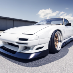
and make further adjustments as necessary.

7. **Final Checks**:
– Double-check all adjustments made. Ensure all bolts are tightened to the manufacturer’s specifications.
– Lower the vehicle back to the ground.

8. **Test Drive**:
– Take the vehicle for a test drive to ensure it handles correctly and that there are no unusual noises or vibrations.

### Conclusion

Proper suspension alignment is crucial for the performance and safety of your Mazda RX-7. By following these detailed steps and using the correct tools, you can achieve a well-aligned suspension that enhances handling and prolongs tire life. always refer to a service manual for specific alignment specifications for your model year, as they may vary. If you’re unsure about any part of the process, it’s wise to consult with a professional mechanic or alignment specialist.
The exhaust manifold gasket is a crucial component in an internal combustion engine, serving as a seal between the exhaust manifold and the engine block. Its primary function is to prevent exhaust gases from leaking out of the exhaust system, ensuring that these gases are directed through the exhaust pipes and ultimately out of the vehicle. This component is typically made from materials that can withstand high temperatures and corrosive substances, such as graphite, metal, or composite materials.

When an engine operates, it generates a significant amount of heat, and the exhaust manifold gasket must endure these extreme conditions. Over time, exposure to heat, pressure, and vibration can cause the gasket to degrade or fail, leading to various issues. A blown or damaged gasket can result in exhaust leaks, which may cause a noticeable decrease in engine performance, increased emissions, and a rise in fuel consumption. Moreover, an exhaust leak can produce a loud, unpleasant noise and may even lead to harmful exhaust fumes entering the vehicle cabin, posing safety risks to occupants.

Replacing an exhaust manifold gasket typically involves a labor-intensive process, as it requires the removal of the exhaust manifold. regular inspections and timely replacement of this component are essential for maintaining optimal engine performance and ensuring the longevity of the exhaust system. Proper installation and the use of high-quality gaskets can help mitigate future issues and enhance overall vehicle reliability.

Download Chevrolet Chevy Malibu Complete Workshop Service Repair Manual 2008 2009 2010 –

service
Tire rotation is an essential maintenance procedure that helps ensure even tire wear, extends the lifespan of the tires, and promotes better handling and safety. click here for more details on the download manual…..


    2019 Chevrolet Malibu Maintenance Reset Quick and simple. Let’s begin!

    Chevrolet Malibu – rust fixed at home

Here’s a detailed guide on how to perform a tire rotation on a Chevrolet Chevy Malibu, including the necessary tools and components.

### Components and Tools Needed:

1. **Tools:**
– **Lug Wrench:** A tool used to loosen and tighten the lug nuts on the wheels.
– **Jack:** A hydraulic or mechanical jack to lift the vehicle off the ground.
– **Jack Stands:** To support the vehicle once it is lifted and ensure safety.
– **Tire Pressure Gauge:** To check the tire pressure after rotation.
– **Torque Wrench:** To ensure lug nuts are tightened to the manufacturer’s specifications.
– **Work Gloves:** Optional for hand protection.

2. **Safety Equipment:**
– **Safety Glasses:** To protect your eyes from debris.
– **Wheel Chocks:** To prevent the vehicle from rolling while it’s lifted.

### Steps for Tire Rotation:

1. **Preparation:**
– **Park the Vehicle:** Ensure the car is on a flat, stable surface. Engage the parking brake to prevent the vehicle from rolling.
– **Gather Tools:** Have all your tools ready and within reach.

2. **Check Tire Pressure:**
– Before you begin the rotation, check the tire pressure using a tire pressure gauge. Ensure they match the recommended specifications listed in the owner’s manual or the sticker inside the driver’s door frame.

3. **Loosen lug Nuts:**
– Using the lug wrench, slightly loosen (but do not remove) the lug nuts on all four wheels. This is easier to do while the tires are still on the ground.

4. **Lift the Vehicle:**
– Use the jack to lift one side of the vehicle at a time. If using a floor jack, place it under the vehicle’s designated jacking point (usually located near the front or rear tires).
– Once the vehicle is lifted, place jack stands under the vehicle at secure points to support it safely.

5. **Remove the Wheels:**
– Remove the loosened lug nuts completely and take off the wheels. Keep the lug nuts in a safe place to avoid losing them.

6. **Rotate the Tires:**
– The recommended tire rotation pattern for a Chevrolet Chevy Malibu typically follows one of these patterns:
– **Front-to-Rear Rotation:** Move the front tires straight back to the rear, and the rear tires straight forward to the front.
– **Cross Rotation:** Move the front tires to the opposite sides of the rear (i.e., the front left to the rear right and the front right to the rear left) while moving the rear tires straight forward.
– If your Malibu has directional tires, ensure they remain on the same side of the vehicle.

7. **Reinstall the Wheels:**
– Place the wheels back onto the hubs and hand-tighten the lug nuts onto the wheel bolts. Ensure the wheel is seated properly against the hub.

8. **Tighten lug Nuts:**
– Using the lug wrench, tighten the lug nuts in a crisscross pattern to ensure even pressure. Don’t fully torque them yet; just make sure they are snug.

9. **Lower the Vehicle:**
– Carefully lower the vehicle back to the ground using the jack. Once the vehicle is fully on the ground, remove the jack sdownload Chevrolet Chevy Malibu workshop manualtands.

10. **Final Torque:**
– With the vehicle on the ground, use a torque wrench to tighten the lug nuts to the manufacturer’s recommended torque specification (usually found in the owner’s manual or on a sticker in the door jamb). This is crucial to prevent the lug nuts from loosening while driving.

11. **Check Tire Pressure Again:**
– After the rotation, check the tire pressure again and adjust it if necessary.

12. **Clean Up:**
– Store all tools and equipment away, and ensure the work area is clean.

### Maintenance Tips:
– Check the owner’s manual for the recommended tire rotation interval, which is typically every 5,000 to 7,500 miles.
– Inspect the tires for any signs of damage, uneven wear, or other issues during the rotation process.
– Consider having your alignment checked if you notice uneven tire wear after rotation.

Performing a tire rotation on your Chevy Malibu is a straightforward task that can be done at home with the right tools and precautions. Regular rotations will help maintain your vehicle’s performance and safety.
The brake master cylinder cap is an essential component of a vehicle’s braking system, designed to provide a secure seal for the brake fluid reservoir housed within the brake master cylinder. This cap serves multiple critical functions that are vital for the safe and efficient operation of the brakes.

Firstly, the brake master cylinder cap prevents contamination of the brake fluid by keeping out dirt, moisture, and other foreign particles. Contaminated brake fluid can lead to corrosion and degradation of the braking components, potentially compromising braking performance and safety. The cap typically features a rubber gasket or seal that ensures a tight fit, minimizing the risk of external debris entering the reservoir.

Secondly, the cap plays a crucial role in maintaining the appropriate pressure within the braking system. As the brake fluid is subjected to changes in temperature and pressure, the cap allows for minor expansions and contractions, preventing fluid leaks while maintaining an optimal environment for braking performance. This is particularly important because brake fluid is hygroscopic, meaning it absorbs moisture from the air. A well-sealed cap helps to minimize this absorption, preserving the integrity of the fluid over time.

Additionally, many brake master cylinder caps come equipped with a warning indicator or venting mechanism. This feature alerts the driver to low brake fluid levels or potential issues within the braking system, prompting necessary maintenance or inspections. Overall, the brake master cylinder cap may appear to be a simple component, but its role is vital in ensuring the reliability and safety of a vehicle’s braking system. Regular inspection and maintenance of the cap and the brake fluid reservoir are essential for optimal vehicle performance and safety.

Download Mazda 626 Station Wagon 1998 Repair Service Manual –

repairs
Repairing a starter motor on a Mazda 626 Station Wagon can be a detailed process. click here for more details on the download manual…..


    MAZDA 626 III Station Wagon (GV)

    How to Diagnose and Replace a Starter Learn how to diagnose and replace a starter in your car or truck. In this video I show you the common causes of a car that doesn’t …

Here’s a reverse-order breakdown of the steps involved in the repair:

### 7. Reconnect the Battery
– Once the starter motor is reassembled and secured in place, reconnect the negative (-) terminal of the battery.

### 6. Reinstall the starter Motor
– Position the starter motor back into its housing. Ensure it aligns properly with the mounting holes.
– Secure it in place with the bolts you previously removed. Tighten them to the manufacturer’s specified torque.

### 5. Reassemble the starter Components
– If you disassembled the starter motor for inspection or cleaning, reassemble the internal components (like brushes, armature, and solenoid) according to the repair manual.
make sure all parts are clean and in good working order.

### 4. test the starter Motor
– Before fully reinstalling, it’s a good idea to test the starter motor using a multimeter. Check for continuity and ensure it operates correctly when powered.

### 3. remove the Old starter Motor
– Disconnect any electrical connections to the starter motor, such as the solenoid wire and the main power cable.
– Unscrew and remove the mounting bolts holding the starter motor in place. Carefully slide the starter motor out.

### 2. Prepare the Work Area
make sure you have the necessary tools (wrenches, sockets, etc.)download Mazda 626 Station Wagon workshop manual and a clean work area to perform the repair.
– Ensure the vehicle is on a flat surface and the ignition is off.

### 1. Safety Precautions
– Before starting any work, ensure the vehicle is in park (or neutral) with the parking brake engaged.
– Wear safety goggles and gloves to protect yourself from potential debris or electrical hazards.

By following these steps in reverse order, you can ensure a methodical approach to repairing the starter motor on a Mazda 626 Station Wagon. Always refer to the vehicle’s service manual for specific details and torque specifications.
The brake rotor screw, often referred to as a brake rotor bolt or rotor retaining screw, is a crucial component in the braking system of a vehicle. This small yet essential fastener is responsible for securing the brake rotor to the wheel hub. The brake rotor, which is a disc-shaped component, plays a vital role in converting the kinetic energy of the moving vehicle into thermal energy through friction when the brakes are applied.

The brake rotor screw ensures that the rotor remains in place during the operation of the braking system. It is typically made of high-strength materials, such as steel or alloy, to withstand the significant forces and heat generated during braking. The design of these screws is such that they can handle the stress exerted by the brake calipers, which clamp down on the rotor to create friction.

Proper installation and torque specifications for brake rotor screws are critical, as loose or improperly secured rotors can lead to brake noise, reduced braking efficiency, and even rotor warping. Over time, these screws may become corroded or stripped, necessitating replacement to maintain optimal performance and safety. Overall, while often overlooked, the brake rotor screw is a fundamental component that contributes to the effectiveness and reliability of a vehicle’s braking system. Proper maintenance and attention to this component are essential for safe driving.

Download HARLEY DAVIDSON SHOVELHEADS 1966-1984Service Manual –

purchase
Overhauling the gear set on a Harley-Davidson Shovelhead engine involves several detailed steps, requiring a solid understanding of engine mechanics and the right tools. click here for more details on the download manual…..


    Shovelhead – Do It Yourself – Tune And Service Guide with Frank Kaisler This Full Length Film is Brought to you by Lowbrow Customs https://www.lowbrowcustoms.com In this instructional video, guru …

    Classic Harley Sound, Shovelhead with Drags

Below is a comprehensive guide to help you through the process. Please ensure you have the necessary skills and tools before attempting this overhaul, as improper handling can lead to severe engine damage.

### Tools and Materials Needed

1. **Basic Hand Tools**: Wrenches, sockets, screwdrivers, pliers, etc.
2. **Torque Wrench**: For accurate torque specifications.
3. **Impact Wrench**: Optional, but can make removing stubborn bolts easier.
4. **Gear Pullers**: For removing gears from shafts.
5. **Seal Puller**: For removing old seals.
6. **Clean Rags**: For cleaning surfaces and wiping down parts.
7. **Engine Oil**: For lubricating components during reassembly.
8. **Gasket Set**: New gaskets for reassembly.
9. **Replacement Gear Set**: If the current gears are worn beyond specifications.
10. **Assembly Lubricant**: For critical components during reassembly.

### Procedure to Overhaul the Gear Set

#### Step 1: Preparation

1. **Disconnect the Battery**: Remove the negative terminal to prevent any electrical shorts.
2. **Drain the Oil**: Remove the oil drain plug and allow the engine oil to fully drain into a suitable container.

#### Step 2: Remove the Primary Drive

1. **Remove the Primary Cover**: Unbolt the primary cover using a socket wrench. Carefully pry it off, ensuring not to damage the gasket.
2. **Remove the Clutch Assembly**: Take off the clutch pressure plate, springs, and friction/disc plates. Use a clutch holder tool if necessary to prevent the assembly from turning.
3. **Remove the Primary Chain**: Disconnect the chain from the front and rear sprockets. Ensure the chain is clean before storage.
4. **Remove the Chaincase**: Remove the bolts securing the chaincase and gently pry it off. Take care not to damage the gasket.

#### Step 3: Remove the Transmission

1. **Disconnect the Shifter Mechanism**: Unbolt the shifter and linkage. Note the position for reinstallation.
2. **Remove the Transmission Mount Bolts**: Unbolt the transmission from its mounting points. Support it as you remove the last bolts to prevent it from dropping.
3. **Disconnect the Output Shaft**: Remove the output shaft nut using a socket wrench. You may need to lock the shaft in place using a special tool.
4. **Remove the Transmission**: Carefully slide the transmission out of the frame.

#### Step 4: Disassemble the Transmission

1. **Remove the End Cover**: Unbolt the end cover from the transmission case. Take care of any internal components that may fall out.
2. **Take Out the Gears and Shafts**: Remove the gears from the main and counter shafts using gear pullers if necessary. Keep track of the order and orientation of all components.

#### Step 5: Inspect Components

1. **Check Gears**: Look for wear, pitting, or damage. Use a micrometer to measure the gears against specifications.
2. **Inspect Bearings**: Check the bearings for wear or damage. Spin them to feel for roughness.
3. **Inspect Seals and Gaskets**: Replace any worn seals or gaskets.

#### Step 6: Replace Gears (if necessary)

1. **Install New Gears**: If you have decided to replace the gears, ensure they are aligned properly on the shafts and press them on carefully.

#### Step 7: Reassemble the Transmission

1. **Install Shafts and Gears**: Place the main and counter shafts back into their respective positions within the transmission case, ensuring they are properly seated.
2. **Install the End Cover**: Bolt the end cover back onto the transmission case, ensuring a proper seal.
3. **Torque Fasteners**: Use a torque wrench to tighten all bolts to the appropriate specifications as listed in the service manual.

#### Step 8: Reinstall the Transmission

1. **Position the Transmission**: Carefully slide the transmission back into its mounting location in the frame.
2. **Reconnect the Output Shaft**: Install the output shaft nutdownload HARLEY DAVIDSON SHOVELHEADS workshop manual and secure it properly.
3. **Reconnect the Shifter Mechanism**: Reattach the shifter linkage to the transmission.

#### Step 9: Reinstall the Primary Drive

1. **Reattach the Chaincase**: Install the chaincase back onto the primary drive, ensuring a new gasket is in place.
2. **Install the Primary Chain**: Reconnect the chain to the front and rear sprockets.
3. **Reinstall the Clutch Assembly**: Place the clutch plates back in order, followed by the pressure plate and springs.
4. **Reattach the Primary Cover**: Bolt the primary cover back on, ensuring a proper seal.

#### Step 10: Final Steps

1. **Refill with Oil**: Pour in the appropriate type and amount of oil into the primary chaincase.
2. **Reconnect the Battery**: Reattach the negative terminal of the battery.
3. **Start the Engine**: Run the engine for a few minutes to check for unusual noises or leaks.

### Conclusion

Overhauling the gear set on a Harley-Davidson Shovelhead is a meticulous process requiring attention to detail. Ensure that all components are properly cleaned, inspected, and replaced as necessary. Always refer to a service manual specific to your bike for torque specifications and detailed diagrams. If you are unsure at any point, it’s advisable to consult with a professional mechanic to avoid potential damage.
The fan belt, also known as the serpentine belt or accessory belt, is an essential component in an internal combustion engine’s system. Its primary function is to drive various peripheral devices that are crucial for the engine’s operation and vehicle functionality. The fan belt typically connects the engine’s crankshaft to components such as the alternator, power steering pump, air conditioning compressor, and water pump.

Made from a durable rubber composite, the fan belt is designed to withstand the high temperatures and mechanical stresses present in an engine environment. The belt’s design often features grooves or ribs that help it grip the pulleys securely, ensuring efficient power transfer from the engine to the accessories.

Over time, fan belts can wear out due to factors such as heat, friction, and exposure to engine fluids. Signs of a failing fan belt may include squeaking or squealing noises, visible cracks or fraying on the belt surface, or a decrease in the performance of the driven accessories, such as dimming headlights or a malfunctioning air conditioning system.

Regular maintenance, including inspection and replacement of the fan belt, is crucial to prevent breakdowns and ensure the smooth operation of the vehicle. Neglecting to maintain the fan belt can lead to complete failure, resulting in significant engine damage and costly repairs.

Download HYUNDAI Crawler Excavator R300LC-7 Service Manual –

fix
Certainly! click here for more details on the download manual…..


    Vauxhall Meriva MPV review – CarBuyer Vauxhall Meriva MPV 2014 review: http://bit.ly/1hsu2al Subscribe to the Carbuyer YouTube channel: http://bit.ly/17k4fct Subscribe …

    Here’s a detailed guide on how to replace the radiator on a Hyundai Crawler Excavator R300LC-7, including descriptions of the tools you may need.

    ### Tools Required:
    – **Wrench Set**: A set of metric wrenches for loosening and tightening bolts and nuts.
    – **Socket Set**: A ratchet and socket set, preferably metric, for accessing tighter spaces.
    – **Pliers**: Adjustable or locking pliers for handling hoses and clips securely.
    – **Flathead and Phillips Screwdrivers**: For removing any screws that may hold panels or components in place.
    – **Radiator Hose Clamp Tool**: This tool makes it easier to remove and install hose clamps without damaging the hoses or clamps.
    – **Coolant Drain Pan**: To catch any coolant that spills when removing the radiator.
    – **Shop Towels or Rags**: For cleaning up spills and wiping down components.
    – **Torque Wrench**: To ensure that bolts are tightened to the manufacturer’s specified torque settings during reassembly.
    – **Safety Gear**: Gloves, goggles, and protective clothing to ensure safety during the process.

    ### Replacement Process:
    – **Preparation**:
    – Ensure the excavator is parked on a flat, stable surface.
    – Turn off the Engine and allow it to cool completely to avoid burns from hot components.

    – **Drain Coolant**:
    – Locate the drain valve on the bottom of the radiator.
    – Place the coolant drain pan beneath the valve and open it to drain the coolant.
    – Once drained, close the valve and dispose of the coolant properly.

    – **Remove Hoses**:
    – Identify and carefully remove the upper and lower radiator hoses using the radiator hose clamp tool or pliers.
    – Slide the clamps away from the hose ends and gently twist and pull the hoses off.

    – **Disconnect Electrical Connections**:
    – Identify any electrical sensors or fans connected to the radiator.
    – Carefully disconnect these connections, taking note of where each connection goes for easier reassembly.

    – **Unbolt Radiator**:
    – Use the wrench or socket set to remove bolts securing the radiator to the mounting brackets.
    – Be cautious of any additional brackets or supports that may need to be removed.

    – **Remove Radiator**:
    – After all connections and bolts are removed, carefully lift the radiator out of its compartment.
    – It may be helpful to have an assistant to help maneuver the radiator out to avoid damage.

    – **Inspect and Clean**:
    – Inspect the radiator mounting area for any debris or old sealant that may need to be cleaned.
    – Ensure that the new radiator fits properly in the space provided.

    – **Install New Radiator**:
    – Carefully position the new radiator in place, aligning it with the mounting brackets.
    – Reinstall and tighten the mounting bolts securely using the wrench or socket set.

    – **Reconnect Hoses**:
    – Reattach the upper and lower radiator hoses, ensuring they are seated properly.
    – Slide the clamps back into position and tighten them securely to prevent leaks.

    – **Reconnect Electrical Connections**:
    – Reconnect any electrical sensors, fans, or other components that were disconnected earlier, ensuring that each connection is secure.

    – **Refill Coolant**:
    – Open the radiator capdownload HYUNDAI Crawler Excavator R300LC 7 workshop manual and refill with the appropriate type and mixture of coolant.
    – Keep an eye on the overflow tank to ensure it is filled to the recommended level.

    – **Check for Leaks**:
    – Start the Engine and let it run for a few minutes while checking for any leaks around the hoses, clamps, and radiator.
    – Monitor the temperature gauge to ensure the system is functioning properly.

    – **Final Inspection**:
    – After confirming there are no leaks and the system is operating normally, double-check that all tools and materials have been removed from the work area.
    – Close the hood or access panels securely.

    – **Dispose of Old Radiator and Coolant**:
    – Properly dispose of the old radiator and any used coolant according to local regulations.

    ### Additional Tips:
    – Always consult the excavator’s service manual for specific instructions and torque specifications as they can vary by model.
    – If unsure about any step, consider consulting a professional mechanic to avoid damage to the machinery or personal injury.
    A blow-off valve (BOV) is a crucial component in turbocharged and supercharged engines, specifically designed to manage boost pressure and enhance Engine performance. Its primary function is to release excess pressure from the intake manifold when the throttle is closed, such as during gear shifts or rapid deceleration. When a driver suddenly removes their foot from the accelerator, the airflow intended for the Engine is abruptly cut off, causing a buildup of pressure in the intake system. If this pressure is not released, it can lead to compressor surge, which may damage the turbocharger and reduce its efficiency.

    The blow-off valve operates by opening to vent the excess pressure to the atmosphere or recirculating it back into the intake system, depending on the type of BOV used. There are two main types: atmospheric and recirculating. Atmospheric BOVs release the pressure into the environment, creating a distinctive “whoosh” sound that many car enthusiasts appreciate. In contrast, recirculating BOVs direct the vented air back into the intake before the turbocharger, helping maintain the boost pressure within the system and improving Engine response.

    In addition to protecting the turbocharger, the blow-off valve can also enhance Engine performance by ensuring smoother airflow, reducing turbo lag, and maintaining optimal boost levels. Overall, the BOV is an essential piece of hardware in performance tuning, contributing to both the longevity of the Engine components and the driving experience.

    Download 2014 VAUXHALL MERIVA B Service and Repair Manual –

    australia
    Certainly! click here for more details on the download manual…..


      Vauxhall Meriva MPV review – CarBuyer Vauxhall Meriva MPV 2014 review: http://bit.ly/1hsu2al Subscribe to the Carbuyer YouTube channel: http://bit.ly/17k4fct Subscribe …

      Battery & alternator health check Opel Vauxhall Meriva B. Voltage test multimeter. Winter che… Winter check. Battery & alternator health check opel meriva b. Voltage test with multimeter. Full tutorial on how to make sure your …

    Here’s a reverse order guide on how to perform power steering repair on a Vauxhall Meriva B. this guide assumes you have a basic understanding of automotive repair. Please ensure you have the proper tools and safety equipment before beginning any repair work.

    ### 6. Reassemble and Test
    – **Reconnect Battery**: Reattach the negative terminal of the battery.
    – **Fill Power Steering Fluid**: Check the power steering fluid reservoir and fill it to the appropriate level with the correct type of fluid.
    – **Start Engine**: Start the engine and let it idle. Turn the steering wheel from lock to lock several times to bleed the system of air.
    – **Check for Leaks**: Inspect all connections and hoses for any signs of leaks while the engine is running.
    – **Test Drive**: take the vehicle for a short test drive to ensure the power steering is functioning correctly.

    ### 5. Install New Components
    – **Install New Steering Rack/ Pump**: Position the new steering rack or pump in place and secure it with the necessary bolts.
    – **Connect Hoses**: Reconnect all hoses and ensure they are tightened properly. Use new O-rings if necessary.
    – **Reconnect Electrical Connectors**: If applicable, reconnect any electrical connectors to the power steering pump.

    ### 4. Remove Old Components
    – **Disconnect Hoses**: Using appropriate tools, disconnect the power steering hoses from the pump and rack. Be prepared for fluid spillage.
    – **Remove Steering Rack/Pump**: Unbolt the old steering rack or pump from its mounting points, and carefully remove it from the vehicle.
    – **Remove Any Obstructions**: Depending on the model, you may need to remove other components (like the engine splash shield or subframe) to access the steering components.

    ### 3. Prepare for Repair
    – **Lift Vehicle**: Safely lift the vehicle using jack stands or a hydraulic lift to access the steering components.
    – **Secure Workspace**: Ensure the area is clean and free of any obstacles.

    ### 2. Gather Tools and Replacement Parts
    – **Tools Needed**: Gather necessary tools such as wrenches, sockets, screwdrivers, pliers, and a fluid catch pan.
    – **Replacement Parts**: Obtain the necessary replacement parts (steering rack, power steering pump, hoses, or fluid) based on the diagnosis.

    ### 1. Diagnose the Problem
    – **Check Fluid Levels**: Start by checking the power steering fluid level, looking for leaks or signs of contamination.
    – **Inspect Components**: Inspect the power steering pump, steering rack,download VAUXHALL MERIVA B workshop manual and hoses for any signs of wear, leaks, or damage.
    – **Test Steering Function**: Turn the steering wheel to identify any unusual noises or resistance, which can indicate a problem with the power steering system.

    ### Safety Tips:
    – Always work in a well-ventilated area.
    – Use protective eyewear and gloves.
    – If unsure about any step, consult a professional mechanic or refer to a repair manual specific to the Vauxhall Meriva B.

    This reverse order guide outlines the steps involved in power steering repair. Always refer to the service manual for detailed instructions and specifications tailored to your vehicle model.
    Clear coat is a transparent layer of paint applied over the base color of a vehicle’s exterior to enhance its appearance and provide protection. Typically composed of acrylic or polyurethane resins, clear coat serves multiple vital functions in automotive finishes. Its primary role is to provide a glossy, high-shine finish that enhances the visual appeal of the car, making the colors appear more vibrant and deep. this glossy layer helps to create a smooth surface that reflects light effectively, giving the vehicle a polished look.

    In addition to aesthetic benefits, clear coat plays a critical role in protecting the underlying paint from environmental elements. It acts as a barrier against UV radiation, which can cause fading and oxidation over time. The clear coat also offers protection against other harmful factors such as harsh weather, bird droppings, tree sap, and road debris. By shielding the paint beneath, clear coat can significantly extend the lifespan of a vehicle’s finish, minimizing the need for frequent repainting.

    Moreover, clear coats can be formulated to include additional properties, such as scratch resistance and self-healing capabilities, further enhancing their protective qualities. However, it is essential to maintain the clear coat properly through regular washing and waxing to preserve its integrity and appearance. Overall, clear coat is a crucial element in automotive finishes, combining beauty and durability to keep vehicles looking their best for years.

    Download JCB 406, 409 Wheel Loading Shovel Service Repair Manual –

    buy
    Adjusting the gear ratio on a JCB 406 or 409 Wheel Loading Shovel is a complex process that involves several steps and requires specialized tools and knowledge. click here for more details on the download manual…..


      How to operate your JCB Compact Wheel Loader For more information please follow the link below: https://www.jcb.com/en-gb/products/wheel-loaders Get to know your compact …

      2000 JCB 409B wheel loader for sale at auction | bidding closes May 7, 2019 View details and pictures — and place your bid at …

    Here’s a detailed breakdown of the tools needed and the process involved:

    ### Tools Required:
    – **Torque Wrench**:
    – Used to apply a specific amount of torque to fasteners, ensuring they are tightened to the manufacturer’s specifications.

    – **Socket Set**:
    – A variety of sockets (including deep sockets) to fit different bolt sizes on the wheel loader. Ensures that you can access and remove the necessary components.

    – **Wrenches**:
    – Adjustable and fixed wrenches to handle various nuts and bolts that may not be accessible with sockets.

    – **Pliers**:
    – For gripping, twisting, and cutting any wiring or small components as needed during adjustment.

    – **Screwdrivers**:
    – Both flathead and Phillips to remove or adjust any covers or components that may obstruct access to the gear components.

    – **Jack and Stands**:
    – To safely lift and secure the wheel loader before beginning work on the undercarriage.

    – **Oil Drain Pan**:
    – For catching any fluids that may need to be drained during the adjustment process.

    – **Measuring Tools**:
    – Calipers or a micrometer to measure gear components for precision adjustments.

    – **Service Manual**:
    – The vehicle’s specific manual provides diagrams and specifications for gear ratios and adjustment procedures.

    ### Adjustment Process:
    – **Safety First**:
    – Engage the parking brake and ensure the machine is on a flat surface. Use wheel chocks for additional safety. Wear protective gear including gloves and safety glasses.

    – **Prepare the Machine**:
    – Use a jack to lift the front of the loader. Secure it with jack stands to prevent it from falling during the adjustment.

    – **Drain Fluids**:
    – If necessary, drain the transmission or differential fluid into an oil drain pan to prevent spills and make it easier to access the components.

    – **Remove Covers**:
    – Use screwdrivers and wrenches to remove any covers or shields that protect the gear assembly. This may include side panels or undercarriage covers.

    – **Inspect current Gear Ratio**:
    – Before making adjustments, measure the current gear ratio by checking the size of the gear teeth and their arrangement. compare these measurements with those provided in the service manual.

    – **Adjust Gear Components**:
    – Depending on the design, you might need to replace gears or adjust the alignment of the existing gears. This could involve loosening bolts with a torque wrench or socket and repositioning gears according to the desired ratio.

    – **Reassemble Components**:
    – Once adjustments are made, carefully reassemble any removed components. Use the torque wrench to ensure bolts are tightened to the manufacturer’s specifications.

    – **Refill Fluids**:
    – Refill the transmission or differential with the appropriate typedownload JCB 406 409 Wheel Loading Shovel workshop manual and amount of fluid, as specified in the service manual.

    – **Test the Adjustment**:
    – Start the machine and conduct a test run. Pay attention to how the machine operates under load to ensure the new gear ratio is functioning as intended.

    – **Final Inspection**:
    – After testing, inspect all components for any signs of leaks or abnormal wear. Ensure all tools are removed from the work area and that the machine is in a safe, operable condition.

    ### Conclusion:
    Adjusting the gear ratio on a JCB 406 or 409 Wheel Loading Shovel requires careful attention to detail, the right tools, and a thorough understanding of the machinery. always refer to the manufacturer’s service manual for specific instructions and safety precautions. If uncertain, it’s advisable to consult with a professional technician.
    The emission control valve is a critical component of a vehicle’s emission control system, which is designed to reduce the release of harmful pollutants into the atmosphere. This valve plays a significant role in managing the flow of gases and vapors from the fuel system and the engine, ensuring that emissions comply with regulatory standards.

    Typically found in systems such as the Evaporative Emission Control System (EVAP), the emission control valve helps prevent the escape of fuel vapors from the fuel tank into the atmosphere. It operates by controlling the flow of these vapors to the engine, where they can be burned during the combustion process instead of being released into the environment. This not only helps reduce hydrocarbon emissions but also improves fuel efficiency.

    The emission control valve can be electronically or mechanically operated. In modern vehicles, it is often controlled by the engine control unit (ECU), which monitors various parameters such as engine temperature and pressure to optimize performance. When the engine is running, the valve opens and closes at specific intervals, allowing for the effective recycling of fuel vapors and maintaining optimal air-fuel ratios.

    Failure of the emission control valve can lead to increased emissions, reduced engine performance, and can trigger warning lights on the dashboard. Regular maintenance and timely replacement of a faulty valve are essential for ensuring compliance with environmental regulations and for the overall health of the vehicle’s engine.

    Download New Holland 900W Operators Manual –

    bookshop
    Replacing the valve body on a Holland 900W s involves several steps that should be followed carefully to ensure proper installation and functionality. click here for more details on the download manual…..


      Mantenimiento a Generadores: Verificar el Aceite

      The Truth about FAT Tire Ebikes: Sidestep the Bullsh💩 https://tailhappytv.com click here to see my favorite ebikes ⚡️ The pitfalls and deception to look out for when buying a 750w …

    Here’s a reverse order outline of the process:

    ### 8. Reassemble the Transmission
    – **Reconnect Electrical Connections**: Reattach any electrical connectors that were disconnected during the removal process.
    – **Reinstall the Transmission Pan**: Place a new gasket on the pan (if applicable) and bolt it back onto the transmission securely.
    – **Fill Transmission Fluid**: Refill the transmission with the appropriate type and amount of fluid through the dipstick tube.

    ### 7. Install the New Valve Body
    – **Position the New Valve Body**: Carefully align the new valve body with the transmission casing and gently lower it into place.
    – **Secure the Valve Body**: Tighten all bolts to the manufacturer’s specifications to ensure a secure fit.

    ### 6. Remove the Old Valve Body
    – **Disconnect Any Remaining Connections**: Ensure all hoses and electrical connectors are fully detached.
    – **Unscrew the Bolts**: Remove all bolts securing the old valve body to the transmission.
    – **Lift Out the Valve Body**: Carefully lift the old valve body out of the transmission casing.

    ### 5. Prepare for Removal
    – **Drain Transmission Fluid**: Place a drain pan underneath and remove the drain plug or the transmission pan to allow fluid to drain out.
    – **Disconnect the Battery**: Disconnect the negative terminal of the battery to prevent any electrical issues.

    ### 4. Access the Valve Body
    – **Remove the Transmission Pan**: Unscrew and take off the transmission pan to expose the valve body.
    – **Remove Any Obstructions**: Take off any components or brackets that might obstruct access to the valve body.

    ### 3. Safety Precautions
    – **Gather Tools and Parts**: Collect necessary tools (socket set, torque wrench, etc.) and the new valve body.
    – **Read the Service Manual**: Familiarize yourself with the specific instructions and torque specifications for your model.

    ### 2. Prepare the Workspace
    – **Ensure a clean Area**: Work in a clean, organized space to avoid contamination.
    – **Use Proper Safety Gear**: Wear gloves and safety glasses to protect yourself during the replacement process.

    ### 1. Assess the Situation
    – **Diagnose the Issue**: Confirm that the valve body is indeed the problem by checking for symptoms like slipping, harsh shifting, or fluid leaks.

    ### Conclusion
    Following these steps in reverse order can help you undersdownload Holland 900W s workshop manualtand the valve body replacement process on a Holland 900W s. Always refer to the specific service manual for detailed instructions and specifications related to your model for the best results. If you’re not experienced with auto repairs, consider consulting a professional mechanic.
    A bumper is a crucial component of a vehicle’s structure, typically located at both the front and rear ends. Its primary function is to absorb impact during low-speed collisions, thereby protecting the more delicate parts of the vehicle, such as the engine, transmission, and other vital systems. Bumpers are designed to minimize damage to both the vehicle itself and any other objects or vehicles it may come into contact with.

    Modern bumpers are usually constructed from a combination of materials, including plastic, rubber, and metal. This blend allows for a lightweight yet durable structure that can absorb energy during an impact. Many bumpers also incorporate energy-absorbing elements, such as foam or crumple zones, which further enhance their ability to mitigate damage. In addition to their protective role, bumpers often house various features, including sensors, lights, and towing attachments.

    Moreover, bumpers play a significant role in a vehicle’s aesthetics and aerodynamics. Manufacturers often design them to align with the overall style of the vehicle, enhancing its visual appeal. In terms of regulations, bumpers must meet specific safety standards set by government agencies, ensuring they provide adequate protection in the event of a collision. Overall, bumpers are integral to a vehicle’s safety, functionality, and design, serving as the first line of defense in automotive safety.

    Download 2004-2005 Subaru impreza WRX STI Service Repair Manual –

    repair
    Performing a transmission fluid pressure test on a Subaru Impreza WRX STI involves several steps and requires specific tools and equipment. click here for more details on the download manual…..


      Bader’s 17 STI vs 600whp+ C6 Vette 17 Sti takes down 600whp+ C6 Vette STI Mods -Built Motor -PTE 6870 Turbo -ETS Turbo Kit -ETS FMIC -Tuned on E98 -Medium …

      New wheel bearings and ARP studs for the Boostaholics GC8 RSTI Subaru Impreza Working on the Boostaholics GC8 seemed like it had become more of a lifestyle than something to do; there was that much work …

    below is a detailed guide on how to conduct this test, including descriptions of the necessary components:

    ### Tools and Equipment Needed

    1. **Transmission Pressure Gauge Kit**:
    – A gauge that can measure hydraulic pressure, typically ranging from 0 to 300 PSI.
    – Includes adapters for various transmission lines.

    2. **Wrenches and Sockets**:
    – Standard and metric wrenches for removing components.
    – Ratchet and socket set for bolts.

    3. **Screwdriver Set**:
    – Flathead and Phillips screwdrivers for various fasteners.

    4. **Pliers**:
    – To remove clamps or hoses.

    5. **Fluid Catch Pan**:
    – A container to catch any fluid that may spill during the process.

    6. **Transmission Fluid**:
    – Ensure you have the correct type of fluid for your Subaru (typically Subaru ATF for automatic transmissions).

    7. **Safety Gear**:
    – Gloves, safety glasses, and possibly a face mask for protection against fluid.

    ### Preparation Steps

    1. **Safety First**:
    – Park the vehicle on a level surface and engage the parking brake. Ensure that the engine is off and cool before beginning.

    2. **Gather Materials**:
    – Have all tools and equipment ready and easily accessible.

    3. **Lift the Vehicle**:
    – If necessary, use a hydraulic jack to lift the front of the vehicle and secure it with jack stands to access the transmission area.

    ### Conducting the Pressure Test

    1. **Locate the Transmission Test Port**:
    – On the Subaru Impreza WRX STI, the test port is usually located on the transmission itself. Refer to the service manual for the exact location, as it may vary by year.

    2. **Remove the Test Port Plug**:
    – Use the appropriate wrench to carefully remove the test port plug. Be prepared for some fluid to spill out. Use a catch pan to collect any fluid.

    3. **Install the Pressure Gauge**:
    – Take the transmission pressure gauge and attach it to the test port. Ensure it is securely connected to avoid leaks.
    – If necessary, use the appropriate adapter to make the connection.

    4. **Start the Engine**:
    – With the gauge connected, start the engine and allow it to idle. Make sure the vehicle is in park (for automatic transmissions) or neutral (for manual transmissions).

    5. **Check Pressure Readings**:
    – Observe the pressure gauge readings. You will typically want to check the pressure at various points:
    – **Idle**: Note the pressure at idle. The typical range should be specified in the service manual.
    – **In Gear**: Shift the transmission into gear (Drive or Reverse) and observe the pressure reading.
    – **WOT (Wide Open Throttle)**: If specified, perform this test to measure pressure at full throttle.

    6. **Compare Readings**:
    – Compare the readings to the specifications in the service manual. Abnormal readings can indicate issues such as low fluid levels, pump problems, or internal leaks.

    7. **Shut Off the Engine**:
    – After taking the necessary readings, turn off the engine.

    8. **Remove the Gauge**:
    – Carefully unscrew the pressure gauge from the test port. Be cautious of any remaining fluid that may spill.

    9. **Reinstall the Test Port Plug**:
    – Use a new sealing washer if necessarydownload Subaru impreza WRX STI workshop manual and reinstall the test port plug securely.

    ### Final Steps

    1. **Check Fluid Level**:
    – After the test, check the transmission fluid level. If any fluid was lost during the test, top it off using the correct type of transmission fluid.

    2. **Inspect for Leaks**:
    – Start the vehicle again and inspect the test port for any leaks.

    3. **Lower the Vehicle**:
    – If the vehicle was lifted, safely lower it back to the ground after ensuring all tools and equipment are removed from underneath.

    ### Conclusion

    A transmission fluid pressure test helps diagnose potential transmission issues on a Subaru Impreza WRX STI. Properly interpreting the pressure readings is crucial for identifying problems. If you find any anomalies in the pressure readings, consult a professional mechanic or refer to the service manual for further diagnostic steps. Always follow safety precautions when working under the vehicle and handling transmission fluid.
    Cruise control is an advanced automotive feature designed to enhance driving convenience and fuel efficiency during long-distance travel. It allows a vehicle to maintain a constant speed without the driver needing to keep their foot on the accelerator pedal. Typically activated by the driver, either via a button or a stalk on the steering wheel, cruise control engages once the vehicle reaches a desired speed, which can range from around 25 mph to the maximum speed limit of the vehicle.

    Once activated, the system takes over the throttle control, adjusting the engine’s power output to maintain the set speed. This can significantly reduce fatigue during long drives, as the driver can relax their foot and maintain a more comfortable posture. Additionally, it promotes better fuel economy since maintaining a steady speed often leads to improved gas mileage compared to frequent acceleration and deceleration.

    Modern vehicles often feature adaptive cruise control, which enhances traditional systems by incorporating radar and cameras to monitor traffic conditions. This advanced technology automatically adjusts the vehicle’s speed in response to slower-moving traffic, thereby improving safety by reducing the risk of collisions. Overall, cruise control is a practical and increasingly sophisticated component that contributes to the overall driving experience, making it safer and more enjoyable.

    Download New Holland LS190 Skid Steer Loader Operators Owners Maintenance Manual –

    discount
    Overhauling the gear set on a Holland LS190 Skid Steer Loader can be a complex task, especially for someone with little mechanical experience. click here for more details on the download manual…..


      New Holland LS190 SkidSteer Operation Video Video showing the operation of the New Holland Skid Steer.

      New holland ls190 skid steer For sale.

    However, I’ll break it down into simpler steps, explaining the process in a way that’s easier to understand. Before you start, ensure you have the right tools, safety equipment, and a service manual for reference.

    ### Tools and Materials Needed:
    1. **Basic Hand Tools**: Wrenches, sockets, screwdrivers, pliers, etc.
    2. **Torque Wrench**: To ensure bolts are tightened to the manufacturer’s specifications.
    3. **Pry Bar**: For removing stubborn parts.
    4. **Gear Oil**: To refill the gear set after overhaul.
    5. **Cleaning Supplies**: Rags, brushes, and degreasers.
    6. **Replacement Parts**: Gaskets, seals, bearings, and any worn gear components.

    ### Safety Precautions:
    – **Wear Safety Gear**: Gloves, safety glasses, and steel-toed boots.
    – **Work in a Well-Ventilated Area**: Preferably outdoors or in a garage with good airflow.
    – **Disconnect the Battery**: To prevent accidental starts.

    ### Step-by-Step Overhaul Process:

    1. **Preparation**:
    – **Read the Manual**: Familiarize yourself with the machine and specific gear set components.
    – **Gather Tools**: Ensure you have everything ready before starting.

    2. **Drain the Gear Oil**:
    – **Locate the Drain Plug**: This is usually at the bottom of the gear case.
    – **Place a Container**: Position a container to catch the old oil as you remove the plug.
    – **Remove the Plug**: Allow the oil to drain completely.

    3. **Remove the Gear Set**:
    – **Access the Gear Set**: This may involve removing panels or covers. Use your manual to identify how to access the gear set.
    – **Disconnect Components**: Carefully disconnect any components that are in the way (like drive shafts or other attachments).
    – **Unbolt the Gear Set**: Use the appropriate socket to remove the bolts holding the gear set in place. Keep track of where each bolt goes.

    4. **Inspect and Clean**:
    – **Check for Wear**: Look for any worn gears, bearings, or seals. If they are damaged, they will need to be replaced.
    – **Clean Surfaces**: Use a degreaser and rags to clean the gear housing and any parts you will be reusing.

    5. **Replace Worn Parts**:
    – **Install New Gears/Seals**: Replace any worn components with new parts. Make sure they are fitted correctly.
    – **Use Gasket Sealant**: If applicable, apply gasket sealant to ensure a good seal when reassembling.

    6. **Reassemble the Gear Set**:
    – **Position the Gear Set**: Carefully place the gear set back into the housing.
    – **Secure with Bolts**: Reinstall and tighten all bolts to the specified torque in the manual.

    7. **Refill with Gear Oil**:
    – **Locate the Fill Plug**: find the fill plug on the gear case.
    – **Pour in New Gear Oil**: Using a funnel, fill the case with new gear oil until it reaches the recommended level. Consult your manual for the specific typedownload Holland LS190 Skid Steer Loader s workshop manual and amount of oil.

    8. **Final Checks**:
    – **Inspect Everything**: Double-check all connections, bolts, and seals to ensure everything is secure.
    – **Reconnect the Battery**: If you disconnected it earlier.

    9. **Test the Loader**:
    – **Start the Loader**: Turn on the skid steer and let it run for a few minutes.
    – **Check for Leaks**: Look underneath for any signs of leaking oil and listen for unusual noises.

    ### Conclusion
    Overhauling the gear set on a Holland LS190 Skid Steer Loader is a detailed process that requires careful attention to detail. If at any point you feel unsure, it’s wise to consult a professional mechanic or technician. Always refer to the service manual for specific instructions and specifications related to your machine. Good luck!
    The windshield, also known as the windscreen in some regions, is a crucial component of a vehicle that serves multiple functions, primarily providing visibility and protection for the driver and passengers. Located at the front of the car, the windshield is made from laminated safety glass, which consists of two layers of glass with a layer of polyvinyl butyral (PVB) sandwiched in between. This construction not only enhances the strength of the glass but also prevents shattering upon impact, thereby reducing the risk of injury from flying glass shards in the event of an accident.

    Beyond its protective role, the windshield contributes to the overall structural integrity of the vehicle. It aids in maintaining the shape of the car’s cabin and plays a vital role in the deployment of airbags during collisions. The design of modern windshields often incorporates features such as tinting for glare reduction, integrated heating elements to prevent frost and ice accumulation, and even advanced technologies like heads-up displays and sensors for advanced driver-assistance systems (ADAS).

    Additionally, windshields are designed to improve aerodynamics, reducing drag and contributing to fuel efficiency. Regular maintenance, including the prompt repair of chips and cracks, is essential for ensuring optimal visibility and safety. Therefore, the windshield is not just a transparent barrier; it is an integral element of automotive engineering that enhances both safety and performance.