Download DODGE CARAVAN 2003 (+Diesel) Service Manual –

bookstore
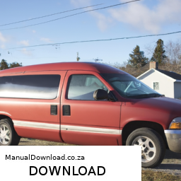
Replacing the control arm on a Dodge Caravan may seem daunting if you have little mechanical experience, but with some basic tools and a little patience, you can do it! click here for more details on the download manual…..


    2012 Dodge Caravan V6 EXHAUST w/ MUFFLER DELETE! We could not find the black exhaust tips on Amazon. Below are black exhaust tips that are similar** WANT 4 INCH BLACK …

    How to Change Engine Oil 2008-2020 Dodge Grand Caravan Buy Now! New Engine Oil Filter from 1AAuto.com https://trq.video/ia-1AEEK00901 New Engine Oil Filter from 1AAuto.com …

Here’s a step-by-step guide to help you through the process:

### Tools and Materials Needed:
– Jack and jack stands
– Lug wrench
– Socket set
– Wrench set
– Pliers
– Hammer
– Replacement control arm
– Torque wrench (optional but recommended)
– Safety glasses and gloves

### Step-by-Step Guide:

#### 1. **Prepare Your Vehicle**
– **Safety First:** Park your Dodge Caravan on a flat surface and turn off the engine. Engage the parking brake.
– **Gather Tools:** Make sure you have all the tools and the new control arm ready.

#### 2. **Lift the Vehicle**
– **Loosen Lug Nuts:** Use the lug wrench to slightly loosen the lug nuts on the front wheels (do not remove them completely yet).
– **Jack Up the Vehicle:** Use the jack to lift the front of the vehicle. Once it’s elevated, place jack stands underneath for safety.
– **Remove the Wheels:** Now, completely remove the lug nuts and take off the front wheels.

#### 3. **Locate the Control Arm**
– The control arm is a metal arm connecting the wheel assembly to the vehicle frame. It’s usually located near the bottom of the vehicle’s suspension.

#### 4. **Remove Old Control Arm**
– **Disconnect the Ball Joint:** Use a socket and wrench to remove the nut that holds the ball joint to the control arm. you may need to use a hammer to gently tap the ball joint free if it’s stuck.
– **Remove Bolts:** Locate the bolts that secure the control arm to the vehicle frame and the steering knuckle. Use a socket and wrench to remove these bolts.
– **Take Out the Control Arm:** Once all bolts are removed, carefully take out the old control arm from the vehicle. Be mindful of any attached components.

#### 5. **Install the New Control Arm**
– **Position the New Control Arm:** place the new control arm into position in the same place as the old one.
– **Reattach Bolts:** Secure the control arm to the vehicle frame and the steering knuckle by threading the bolts back in. Make sure everything is aligned correctly.
– **Tighten the Bolts:** Use a torque wrench (if available) to tighten the bolts to the manufacturer’s specifications. If you don’t have a torque wrench, make sure they are tight but do not overtighten.

#### 6. **Reconnect the Ball Joint**
– Attach the ball joint to the control arm and secure it with the nut you removed earlier. Again, ensure it is tight.

#### 7. **Reinstall Wheels**
– Put the wheels back ondownload DODGE CARAVAN + workshop manual and hand-tighten the lug nuts.
– Lower the vehicle from the jack stands and then fully tighten the lug nuts with the vehicle on the ground.

#### 8. **Final Checks**
– Go through all the bolts and ensure everything is tight and secure.
check to make sure there are no tools or parts left under the vehicle.

#### 9. **Test Drive**
– Start the vehicle and take it for a short test drive to ensure everything is working properly. Pay attention to any unusual noises or handling issues.

### Conclusion
Replacing a control arm can be a manageable task with the right tools and a methodical approach. If you encounter any problems or feel unsure at any step, don’t hesitate to ask for help or consult a professional mechanic. Always prioritize safety!
The master cylinder is a crucial component of a vehicle’s hydraulic brake system, playing a vital role in ensuring effective and reliable braking performance. It is essentially a cylindrical container that houses brake fluid and serves as the starting point for the hydraulic force that activates the brakes. When a driver presses the brake pedal, the force is transmitted to the master cylinder, which then compresses the brake fluid inside it.

This compression generates hydraulic pressure, which travels through brake lines to the brake calipers or wheel cylinders at each wheel. As the hydraulic pressure builds up, it forces the brake pads against the rotors (in disc brakes) or the brake shoes against the drums (in drum brakes), thereby slowing down or stopping the vehicle. The master cylinder typically consists of different chambers—usually one for the front brakes and one for the rear brakes—allowing for independent operation and enhancing safety.

In modern vehicles, master cylinders can be equipped with additional features such as anti-lock braking systems (ABS) that help prevent wheel lockup during hard braking. Regular maintenance of the master cylinder is essential, as leaks or air bubbles in the brake fluid can lead to brake failure. Thus, understanding the function and importance of the master cylinder is critical for both vehicle safety and performance.

Download New Holland CE LB110.B, LB115.B, LB75.B, LB90.B Operators Manual –

bookshop
Replacing the trailing arm on a Holland CE LB110.B, LB115.B, LB75.B, or LB90.B involves several steps. click here for more details on the download manual…..


    2001 NEW HOLLAND LB90 For Sale http://http://www.machinerytrader.com/listingsdetail/detail.aspx?OHID=9889133 Title: 2001 NEW HOLLAND LB90 For Sale …

Here’s a reverse order breakdown of the process:

### 7. **Reassemble and Tighten Components:**
– Reinstall any removed components such as the wheel, brake drum, and hub.
– Tighten the wheel lug nuts to the manufacturer’s specified torque.
– Reattach any other parts that were removed during the process, ensuring everything is secure.

### 6. **Lower the Equipment:**
– Carefully lower the machine back to the ground using the hydraulic system or jack.
– Remove any jack stands or supports used for safety.

### 5. **Install the New Trailing Arm:**
– Position the new trailing arm in place, aligning it with the mounting points.
– Insert and hand-tighten the bolts or fasteners that secure the trailing arm.

### 4. **Secure the Trailing Arm:**
– Use a torque wrench to tighten the bolts to the manufacturer’s specified torque settings.
– Ensure that all fasteners are secure and that the trailing arm is properly installed.

### 3. **Remove the Old Trailing Arm:**
– Disconnect any components that may be attached to the trailing arm, such as brake lines or sensors.
– Unbolt the old trailing arm from its mounting points using appropriate tools.
– Carefully remove the old trailing arm from the equipment.

### 2. **Prepare for Installation:**
– Ensure the work area is clear and organized.
– Gather all necessary tools, including wrenches, sockets, a torque wrench, and any other specific tools required for your model.

### 1. **Safety Precautions:**
– Before starting, ensure that the equipment is on a flat surface and secured.
– Use wheel chocks to prevent movement.
– Wear appropriate personal protective equipment (PPE).

This reverse order provides a structured approach to replacing a trailing arm in Holdownload Holland CE LB110.B LB115.B LB75.B LB90.B s workshop manualland CE equipment models. Always refer to the specific service manual for detailed instructions and torque specifications for your particular model.
The water pump gasket is a crucial component in an engine’s cooling system, serving as a seal between the water pump and the engine block. Its primary function is to prevent coolant leaks, ensuring that the engine maintains the optimal operating temperature. The water pump circulates coolant through the engine and the radiator, facilitating heat dissipation. Without a properly functioning gasket, the coolant could escape, leading to overheating and potential engine damage.

Typically made from materials like rubber, cork, or composite substances, the water pump gasket is designed to withstand extreme temperatures and pressures within the engine environment. Over time, exposure to heat, coolant, and vibration can cause the gasket to deteriorate, leading to leaks. Symptoms of a failing water pump gasket might include visible coolant puddles beneath the vehicle, an overheating engine, or a drop in coolant levels without any apparent leaks elsewhere.

Replacing a worn or damaged water pump gasket is essential for maintaining the efficiency and longevity of the engine. The process usually involves draining the coolant, removing the water pump, cleaning the mating surfaces, and installing a new gasket before reassembling the components. Regular maintenance checks can help identify issues with the water pump gasket early, preventing more extensive damage and costly repairs. Properly functioning water pump gaskets contribute significantly to the overall health of the engine, making them an essential aspect of automotive care.

Download KOMATSU WB150AWS-2N BACKHOE Loader Operation & Maintenance Manual –

do your own repairs
Replacing the PCV (Positive Crankcase Ventilation) valve on a Komatsu WB150AWS 2N backhoe loader involves several steps. click here for more details on the download manual…..


    VW Volkswagen Eos Roof Seal Cleaning Access, Drain Line Location & Flushing Different service positions for cleaning the seals and drain lines as well as locations.

    Here’s a reverse order guide to help you understand the process from the last step back to the first:

    ### 7. Final Checks
    – **Reconnect the Battery**: If you disconnected the battery, reconnect it.
    – **Start the Engine**: Start the engine and let it idle. check for any leaks or unusual noises.
    – **Inspect Functionality**: Ensure the PCV system is functioning correctly. Look for smooth engine operation and no warning lights.

    ### 6. Install the New PCV Valve
    – **Insert the New PCV Valve**: Place the new PCV valve into the valve cover or designated location. Ensure it fits snugly.
    – **Secure the Valve**: If applicable, use any clamps or screws to secure the valve in place.

    ### 5. Clean the Area
    – **Remove Old Residue**: Clean the area around the old PCV valve and its housing. Use a cloth or a soft brush to remove any oil residue or dirt.
    – **Inspect the Grommet**: check the grommet and surrounding areas for wear and replace if necessary.

    ### 4. Disconnect the Old PCV Valve
    – **Remove any Clamps or Fasteners**: If the PCV valve is held in place with clamps or screws, remove them.
    – **Pull Out the Old Valve**: Gently pull the old PCV valve out of its socket.

    ### 3. Prepare for Replacement
    – **Gather Tools**: Obtain the necessary tools, including wrenches, pliers, and a new PCV valve.
    – **Locate the PCV Valve**: Identify the location of the PCV valve on the engine. It is usually found on the valve cover or intake manifold.

    ### 2. Safety Precautions
    – **Turn Off the Engine**: Ensure the engine is turned off and cooled down.
    – **Disconnect the Battery**: To prevent any electrical hazards, disconnect the negative terminal of the battery.

    ### 1. Gather Replacement Parts
    – **Procure the Correct PCV Valve**: Ensure you have the correct replacement PCV valve for the Komatsu WB150AWS 2N. check the part number against your machine’s specifications.

    By following these steps in reverse order, you should be able to successfully replace the PCV valve on your Komatsu WB150AWS 2N backhoe loader. Always consult the operator’s manual for specific instructionsdownload KOMATSU WB150AWS 2N BACKHOE Loader Operation workshop manual and safety guidelines related to your machine.
    A heat shield is a critical component in automotive engineering designed to protect various parts of a vehicle from excessive heat generated By the engine and exhaust system. Typically made from materials that can withstand high temperatures, such as aluminum, titanium, or specialized heat-resistant composites, heat shields serve to reflect, absorb, or disperse heat, ensuring that sensitive components are not exposed to damaging temperatures.

    Heat shields are strategically placed around areas that are susceptible to heat damage, including electrical wiring, fuel lines, and certain engine components. By mitigating heat transfer, these shields help maintain the integrity and performance of these components, thus enhancing overall vehicle reliability and safety. For example, the heat shield can prevent fuel from vaporizing prematurely in the fuel lines, which is crucial for maintaining engine performance and efficiency.

    Additionally, heat shields contribute to passenger comfort By minimizing heat intrusion into the vehicle’s cabin. They play a vital role in reducing noise and vibration from the engine and exhaust, contributing to a quieter ride. In modern vehicles, heat shields are often tailored to meet specific requirements, including weight reduction and aerodynamic efficiency, making them an essential part of the vehicle’s thermal management system. Overall, heat shields are indispensable for optimizing performance, enhancing safety, and extending the lifespan of automotive components.

    Download 2016 Volkswagen Eos Download Service & Repair Manual –

    service manual
    ### Clutch Plate Replacement on a Volkswagen Eos – **Preparation and Safety** – **Workspace:** Ensure you have a clean, well-lit, and spacious work area. click here for more details on the download manual…..


      VW Volkswagen Eos Roof Seal Cleaning Access, Drain Line Location & Flushing Different service positions for cleaning the seals and drain lines as well as locations.

      Changing Spark Plugs and Coil Packs on a Volkswagen Eos If your car is sputtering when you give it some throttle, you might need to replace your sparkplugs and coil packs. This video …

    ### Clutch Plate Replacement on a Volkswagen Eos

    – **Preparation and Safety**
    – **Workspace:** Ensure you have a clean, well-lit, and spacious work area. A garage or driveway with a concrete floor is ideal.
    – **Safety Gear:** Wear safety glasses and gloves to protect against debris and sharp edges.
    – **Tools Required:**
    – **Basic Tools:** Wrenches, ratchet set, and sockets (including 6-point and 12-point sockets).
    – **Torque Wrench:** For precise torque specifications during reassembly.
    – **Pliers and Screwdrivers:** Flathead and Phillips to remove various clips and screws.
    – **Flywheel lock Tool:** To prevent the flywheel from rotating during the removal process.
    – **Clutch Alignment Tool:** For proper alignment of the new clutch plate during installation.
    – **Jack and Jack Stands:** To safely lift the car and support it while working underneath.
    – **Transmission Jack (optional):** For easier handling of the transmission while removing and reinstalling.

    – **Vehicle Preparation**
    – **Disconnect Battery:** Remove the negative terminal from the battery to prevent electrical shorts.
    – **Lift Vehicle:** Use a jack to raise the front of the Eos and secure it with jack stands. Ensure the vehicle is stable before crawling underneath.

    – **Removing the Transmission**
    – **Remove Underbody Covers:** If applicable, detach any plastic underbody panels to access the transmission.
    – **Driveshaft Removal:** Depending on the configuration, you may need to remove the front driveshafts. Unbolt from the transmission and the wheel hub.
    – **Exhaust System:** If necessary, remove parts of the exhaust system that obstruct access to the transmission.
    – **Shift Linkage:** Disconnect the shifter assembly from the transmission.
    – **Transmission Mounts:** Unbolt the transmission mounts from the vehicle chassis.
    – **Support Transmission:** Use a transmission jack or a sturdy floor jack to support the transmission before unbolting it from the engine.
    – **Unbolt Transmission:** Carefully unbolt the transmission from the Engine block, ensuring to work on all attachment points.

    – **Clutch Assembly Removal**
    – **Flywheel Access:** Once the transmission is safely removed, access the clutch assembly.
    – **Inspect Flywheel:** Check the flywheel for any damage or wear. A resurfacing may be required if it shows signs of excessive wear.
    – **Remove Clutch Pressure Plate:** Unbolt the pressure plate from the flywheel, noting the order and orientation of bolts for reinstallation.
    – **Retrieve Old Clutch Plate:** Carefully slide out the old clutch plate from the assembly. Inspect for any signs of wear, such as cracks or glazing.

    – **Installing the New Clutch Plate**
    – **Clean Surfaces:** Clean the flywheel surface and the pressure plate mounting area to ensure a proper seal and function.
    – **Align New Clutch Plate:** Use the clutch alignment tool to position the new clutch plate correctly against the flywheel.
    – **Install Pressure Plate:** Secure the pressure plate to the flywheel with bolts, tightening them in a crisscross pattern to ensure even pressure.

    – **Reassembling the Transmission**
    – **Reconnect Transmission:** Carefully liftdownload Volkswagen Eos workshop manual 
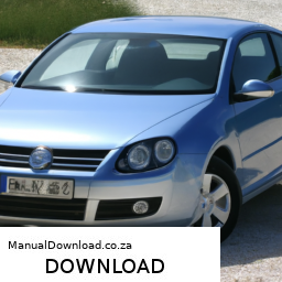
and align the transmission back onto the engine, ensuring proper alignment with the input shaft.
    – **Bolt Transmission:** Reinstall the bolts to secure the transmission to the Engine block, following the correct torque specifications.
    – **Reattach Mounts:** Install the transmission mounts back to the chassis and tighten securely.
    – **Reinstall Driveshafts and Exhaust:** If removed, reconnect the front driveshafts and any parts of the exhaust system.

    – **Final Steps**
    – **Reconnect Shift Linkage:** Reattach the shifter assembly to the transmission.
    – **Replace Underbody Covers:** Reinstall any underbody panels that were removed for access.
    – **Reconnect Battery:** Attach the negative battery terminal back to the battery.
    – **Lower Vehicle:** Remove jack stands and carefully lower the vehicle to the ground.

    – **Testing**
    – **Start Engine:** Start the vehicle and allow it to idle for a few minutes.
    – **Check Clutch Function:** Test the clutch by shifting through gears while stationary to ensure smooth operation.
    – **Road Test:** Take the vehicle for a short drive to verify that the clutch engages and disengages properly without any abnormal noises.

    ### Conclusion
    Replacing the clutch plate on a Volkswagen Eos is a detailed process that requires attention to safety and proper technique. Ensure to follow manufacturer specifications and guidelines throughout the process for optimal results.
    A brake proportioning valve is a crucial component in a vehicle’s braking system, designed to optimize braking performance and enhance safety during deceleration. This valve regulates the distribution of brake fluid pressure between the front and rear brakes, ensuring that each set of brakes engages appropriately based on the vehicle’s weight distribution and load conditions.

    In most vehicles, the front brakes handle a greater portion of the braking force due to the forward weight transfer that occurs during braking. If the rear brakes were to receive the same amount of pressure as the front, it could lead to premature locking of the rear wheels, resulting in a loss of control and potential skidding. The brake proportioning valve addresses this issue by limiting the amount of hydraulic pressure sent to the rear brakes, thereby preventing lock-up and maintaining stability.

    Typically located within the brake line system, the proportioning valve works in conjunction with the master cylinder and wheel cylinders. It adjusts fluid flow based on the vehicle’s braking dynamics, which can change with speed, load, and road conditions. Some modern vehicles utilize electronic brake distribution systems that integrate sensors and control modules to achieve similar objectives, enhancing overall braking efficiency.

    In summary, the brake proportioning valve is essential for achieving balanced braking performance, ensuring that both the front and rear brakes function optimally, contributing to safer driving experiences. Its precise regulation of brake fluid pressure plays a pivotal role in maintaining vehicle stability and control during braking maneuvers.

    Download Komatsu PC600LC-6 Hydraulic Excavator Service & Repair Manual –

    stores
    Shifting the drum on a Komatsu PC600LC-6 Hydraulic Excavator involves several steps and requires specific tools and equipment. click here for more details on the download manual…..


      Komatsu PC 650-8 LC Hydraulic Excavator Walkaround & Inside Cab Conexpo Report The Komatsu PC 650-8 LC is the new Komatsu Excavator presentend at Conexpo 2011. In Las Vegas Komatsu revealed the all …

      KOMATSU pc600lc-6 Hydraulic Excavator with Concrete Pulveriser Not something you see everyday. Looks like a fun job.

    Below is a detailed breakdown of the procedure and the tools needed for a successful drum repair:

    – **Safety Gear**:
    – **Safety Glasses**: Protect your eyes from debris and hydraulic fluid.
    – **Gloves**: Use heavy-duty gloves to protect your hands from sharp edges and heavy components.
    – **Steel-Toed Boots**: Wear protective footwear to prevent injury from falling objects.

    – **Basic Tools**:
    – **Socket Set**: A comprehensive set of sockets (including deep sockets) for loosening and tightening bolts on the drum assembly.
    – **Wrenches**: Adjustable and fixed wrenches to handle various bolt sizes, especially for hydraulic fittings.
    – **Pry Bar**: For maneuvering heavy components and gaining leverage when shifting the drum.
    – **Hammer**: A ball-peen or sledgehammer for tapping components into place or breaking rusted parts loose.

    – **Specialized Tools**:
    – **Hydraulic Jack**: A hydraulic jack is necessary for lifting the excavator securely to access the drum. Ensure it has the capacity to handle the excavator’s weight.
    – **Jack Stands**: Use jack stands to support the excavator once raised; never rely solely on the hydraulic jack for support.
    – **Drum Alignment Tool**: This tool helps ensure the drum is correctly aligned during installation.
    – **Torque Wrench**: For tightening bolts to manufacturer specifications, ensuring a secure and safe assembly.

    – **Preparation**:
    – **Inspect the Work Area**: Clear the area around the excavator of any debris and ensure it is safe to work.
    – **Consult the Manual**: Refer to the Komatsu PC600LC-6 service manual for specific guidelines and torque specifications.
    – **Drain Fluids**: If necessary, drain hydraulic fluids to avoid spills when disconnecting the hydraulic lines.

    – **Lifting the Excavator**:
    – **Position the Hydraulic Jack**: Place the hydraulic jack under a solid lifting point on the excavator.
    – **Lift the Excavator**: Raise the excavator to a safe working height.
    – **Secure with Jack Stands**: Once lifted, place jack stands under the machine to ensure stability.

    – **Removing the Drum**:
    – **Disconnect Hydraulic Lines**: Using wrenches, carefully disconnect hydraulic lines from the drum assembly. Be prepared for some fluid leakage.
    – **Unfasten Bolts**: Use the socket set to remove the bolts securing the drum to the excavator. Keep track of all hardware for reassembly.
    – **Remove the Drum**: Carefully lift the drum off the excavator frame. It may require assistance due to its weight.

    – **Inspecting the Drum**:
    – **Check for Damage**: Look for cracks, wear, or any damage on the drum surface and components.
    – **Clean the Area**: Remove any dirt or debris from the drum mounting area to ensure a good seal during reinstallation.

    – **Installing the New or Repaired Drum**:
    – **Align the Drum**: Position the drum back onto the excavator frame, ensuring it is aligned correctly using the drum alignment tool.
    – **Secure the Drum**: Replace and tighten the specifications provided in the service manual.
    – **Reconnect Hydraulic Lines**: Reattach the hydraulic lines and ensure they are secure to prevent leaks.

    – **Final Checks**:
    – **Double-Check Tightness**: Go through all bolts and connections to ensure everything is tightened properly.
    – **Refill Fluids**: If hydraulic fluids were drained, refill them to the appropriate levels.
    – **Lower the Excavator**: Carefully remove jack stands and lower the hydraulic jack.

    – **Testing**:
    – **Start the Excavator**: Run the engine and operate the hydraulic systems to ensure everything is functioning correctly.
    – **Check for Leaks**: Inspect all hydraulic connections for leaks during operation.
    – **Perform a Test Run**: Conduct a short test run to confirm that the drum is operating smoothly without any unusual noises or issues.

    By following these steps and utilizing the proper tools and safety precautions, you can efficiently shift the drum on a Komatsu PC600LC-6 Hydraulic Excavator. Always refer to the manufacturer’s guidelines for specific details related to your model.
    The fuel return line is an essential component in a vehicle’s fuel delivery system, primarily found in fuel-injected engines. Its primary function is to manage the flow of excess fuel that is not used by the engine during the combustion process. When fuel injection occurs, the fuel pump sends gasoline or diesel from the fuel tank to the engine at a specific pressure. However, not all of the fuel delivered to the injectors is consumed; some of it is returned back to the fuel tank via the fuel return line.

    This return line plays a critical role in maintaining optimal fuel pressure within the fuel rail, ensuring that the injectors receive a consistent supply of fuel. It helps to prevent fuel from becoming too hot and ensures that the fuel system operates efficiently, minimizing the risk of vapor lock, which can occur if fuel evaporates due to excessive heat. The return line is typically made of durable materials resistant to corrosion and pressure fluctuations, such as rubber or reinforced plastic.

    In addition to regulating fuel pressure, the return line contributes to the overall efficiency of the vehicle’s fuel system. By allowing excess fuel to flow back to the tank, it reduces the chances of fuel wastage and helps maintain the engine’s performance. Proper maintenance and inspection of the fuel return line are crucial, as leaks or blockages can lead to fuel system malfunctions, reduced engine performance, and increased emissions.

    Download 1995 Mercedes-Benz S-Class S300SEL (W140) OEM Download Service & Repair Manual Software –

    repair
    Replacing a coil spring on a Mercedes-Benz S-Class S300SEL W140 involves several steps. click here for more details on the download manual…..


      1995 mercedes w140 s500 update and whats next

      Mercedes W140 300SE engine wiring harness rebuild

    Here is a reverse order guide for the process:

    ### 7. Reassembly and Final Checks
    – **Reinstall Wheels:** Place the wheels back on the vehicle and hand-tighten the lug nuts.
    – **Lower the Vehicle:** Use the jack to lower the vehicle back to the ground.
    – **Torque Lug Nuts:** Once the vehicle is on the ground, torque the lug nuts to the manufacturer’s specifications.
    – **Reconnect Battery:** If you disconnected the battery, reconnect it.

    ### 6. Install the New coil Spring
    – **Position the Spring:** Carefully position the new coil spring into the spring seat, ensuring it is seated properly in both the top and bottom mounts.
    – **Compress the Spring:** If necessary, use a spring compressor to safely compress the spring for easier installation.

    ### 5. Reinstall Suspension Components
    – **Attach Shock Absorber:** Reattach the shock absorber to the suspension arm and tighten the bolts to the specified torque.
    – **Reattach Control Arms:** Reinstall any control arms or links that were removed during the process.
    – **Install Any Additional Components:** Reconnect any other components, such as sway bar links or brackets, that were removed.

    ### 4. Remove the Old coil Spring
    – **Detach Suspension Components:** Unbolt the shock absorber and any other components blocking access to the coil spring.
    – **Remove the coil Spring:** Carefully remove the old coil spring from the spring seat. If it’s stuck, ensure all bolts and components are removed before attempting to take it out.

    ### 3. Prepare the Vehicle
    – **Raise the Vehicle:** Use a jack to lift the vehicle and secure it on jack stands.
    – **Remove the Wheels:** Take off the wheels to access the suspension components.

    ### 2. Gather Tools and Safety Equipment
    – **Tools Needed:** You will need a jack, jack stands, lug wrench, socket set, wrench set, spring compressor, and safety equipment (gloves, goggles).
    – **New coil Spring:** Ensure you have the correct replacement coil spring that meets OEM specifications.

    ### 1. Safety First
    – **Park on a Level Surface:** Ensure the vehicle is parked on a flat, stable surface.
    – **Engage the Parking Brake:** To prevent any movement, engage the vehicle’s parking brake.
    – **Disconnect Battery (if necessary):** If you will be working near electrical components, consider disconnecting the battery for safety.

    By following this reverse order guide, you can systematically approach the coil spring replacement process for a Mercedes-Benz S-Class S300SEL W140. Always refer to the vehicle’s service manual for specific torque specificationsdownload Mercedes Benz S Class S300SEL W140 OEM workshop manual and safety procedures.
    The vanity mirror light is a specialized lighting component commonly found in vehicles, particularly in the sun visors or overhead consoles, designed to illuminate the vanity mirror area for drivers and passengers. This feature is especially popular in vehicles aimed at enhancing comfort and convenience for occupants, allowing for better visibility when applying makeup, grooming, or making adjustments before stepping out of the car.

    Typically, the vanity mirror light consists of one or more small light bulbs or LED lights, strategically positioned to provide even lighting without casting harsh shadows. The light is usually activated when the sun visor is flipped down or when the small mirror cover is opened, ensuring that it only illuminates when necessary, thus conserving energy.

    In terms of design, vanity mirror lights are often designed to blend seamlessly with the vehicle’s interior aesthetics, offering a subtle yet functional addition. they can also come with additional features such as dimmability or color temperature adjustments, enhancing the user experience.

    Moreover, the vanity mirror light plays a significant role in enhancing safety by allowing drivers and passengers to check their appearance without needing to exit the vehicle or rely solely on external lighting conditions. Overall, this unassuming component contributes to the overall functionality and user-friendliness of modern vehicles.

    Download 2014 SEAT Ibiza 5-Doors Download Service & Repair Manual –

    diy
    Repairing the reverse gear in a SEAT Ibiza, or any vehicle for that matter, can be a complex task, especially for someone with little mechanical experience. click here for more details on the download manual…..


      SEAT IBIZA 1.6 TDI 95 hp 5 door POV TEST DRIVE POV test drive video of the 2018 SEAT IBIZA 1.6 TDI 95 hp 5 door with FR Trim Level. In this video you can see a daytime test …

      SEAT Ibiza 1.2 TSI 90PS Connect 5-Door SEAT Ibiza 1.2 TSI 90PS Connect 5-Door.

    However, I can provide you with a simplified overview of the process. Please remember that if you’re not comfortable with car repairs, it’s always best to consult a professional mechanic.

    ### Tools and Materials Needed:
    – Wrench set
    – Screwdrivers (flathead and Phillips)
    – Pliers
    – Jack and jack stands
    – Transmission fluid
    – Gear oil
    – Service manual (for specific torque settings and diagrams)

    ### Steps for Reverse Gear Repair:

    1. **Safety First**:
    – Park the vehicle on a flat surface.
    – Turn off the engine and engage the parking brake.
    – Disconnect the battery to avoid any electrical issues.

    2. **Raise the Vehicle**:
    – Use a jack to lift the front of the car and secure it with jack stands. make sure it’s stable before you start working underneath.

    3. **Remove the Transmission**:
    – To access the reverse gear, you will need to remove the transmission. This is a significant task and involves:
    – Disconnecting the driveshafts (the metal rods that transfer power from the engine to the wheels).
    – Unbolting the transmission from the engine and other supporting brackets.
    – Carefully sliding the transmission out from under the car.

    4. **Disassemble the Transmission**:
    – Once the transmission is out, place it on a clean, flat surface.
    – Remove the outer casing (this may require some unbolting and prying).
    – Be careful to keep track of the order of parts as you remove them.

    5. **Inspect the Reverse Gear**:
    – Locate the reverse gear and its corresponding components (like the reverse gear fork and synchronizer).
    – Check for any visible damage such as cracks or wear on the teeth of the gear.

    6. **Replace Damaged Parts**:
    – If you find any damaged parts, you will need to replace them. You can usually purchase these parts from an auto parts store or a SEAT dealership.
    – Follow the instructions in your service manual for installing the new parts.

    7. **Reassemble the Transmission**:
    – Once you’ve replaced any damaged parts, carefully put the transmission back together in the reverse order of disassembly.
    make sure all seals and gaskets are in good condition to prevent leaks.

    8. **Reinstall the Transmission**:
    – Position the transmission back into the car.
    – Reattach it to the engine and secure all bolts and brackets as per the service manual.

    9. **Reconnect Driveshafts**:
    – Reconnect the driveshafts that you previously removed.

    10. **Add Transmission Fluid**:
    – Before you start the car, make sure to fill the transmission with the correct typedownload SEAT Ibiza 5 Doors workshop manual and amount of fluid as specified in the service manual.

    11. **Reattach Battery**:
    – Reconnect the battery terminals.

    12. **Test Drive**:
    start the car and take it for a short test drive to ensure the reverse gear is functioning properly.

    ### Final Thoughts:
    Repairing the reverse gear can be challenging. If at any point you feel unsure, it’s crucial to consult a professional mechanic. Working on a vehicle’s transmission requires precision and experience, and it’s always better to be safe than sorry.
    A wheel bearing is a crucial component of a vehicle’s wheel assembly, responsible for enabling smooth and efficient rotation of the wheels. Typically made from high-strength steel, a wheel bearing consists of a set of steel balls or rollers encased in an inner and outer race. This design allows the wheel to rotate freely while minimizing friction and wear. Wheel bearings are located between the wheel hub and the axle, serving as the interface that supports the weight of the vehicle and absorbs the forces experienced during driving.

    In addition to facilitating smooth wheel rotation, wheel bearings play a vital role in ensuring vehicle safety and performance. They help maintain alignment and stability, allowing for precise handling and control while driving. Over time, wheel bearings can wear out due to factors like exposure to moisture, dirt, and high temperatures, leading to potential issues such as noise, vibration, or even wheel locking. Symptoms of a failing wheel bearing may include a grinding noise coming from the wheel area or a noticeable change in handling, such as pulling to one side.

    Regular inspection and maintenance of wheel bearings are essential for prolonging their lifespan and ensuring safe vehicle operation. If a wheel bearing fails, it can lead to significant damage to the wheel assembly and compromise the safety of the vehicle, making timely replacement vital. Ultimately, wheel bearings are integral to the overall functionality and reliability of any vehicle.

    Download 2003 Suzuki Grand Vitara Service & Repair Manual Software –

    repair manual
    Wheel alignment is an essential maintenance procedure that ensures your vehicle’s wheels are set to the correct angles, allowing them to make proper contact with the road. click here for more details on the download manual…..


      Suzuki Grand Vitara Head Unit Installation 2005-2018 Suzuki Grand Vitara Head Unit Installation 2005-2018. SUBSCRIBE AND FOLLOW FB: …

      Suzuki Grand Vitara 2006-2015 | Should you buy one?? BEST REVIEW…!! Sell Or Buy A Car With Carwow: https://carwow-uk.pxf.io/6eByXV Lease A Car With LeaseLoco: https://leaseloco.sjv.io/LXzKoL …

    Proper alignment helps improve tire life, enhance handling, and ensure safe driving. Below is a detailed guide on how to perform wheel alignment on a Suzuki Grand Vitara, including the necessary components and steps.

    ### Tools and Equipment Needed

    1. **Alignment Machine or Alignment Tools**: Professional alignment requires specialized equipment, but you can also use basic tools if you’re doing a DIY alignment.
    – **Alignment Heads or Targets**: Used to measure the angles of the wheels.
    – **Camber Gauge**: Measures camber angle.
    – **Toe Plates**: Used for measuring toe angle.

    2. **Basic Hand Tools**:
    – Wrenches (particularly socket wrenches)
    – Ratchet
    – Screwdrivers
    – Torque wrench

    3. **Floor Jack and Jack Stands**: To lift the vehicle safely for access to suspension components.

    4. **Measuring Tape or Ruler**: For precise measurements.

    5. **Chalk or Marker**: To mark measurements on the tires.

    ### Components Involved in Wheel Alignment

    1. **Camber**: The angle of the wheels in relation to the vertical axis. Positive camber means the top of the wheel is tilted outward; negative camber means it’s tilted inward.

    2. **Toe**: The angle of the wheels in relation to the centerline of the vehicle when viewed from above. Toe-in means the front of the wheels is closer than the rear, while toe-out means they are farther apart.

    3. **Caster**: The angle of the steering pivot when viewed from the side of the vehicle. Positive caster helps with steering stability.

    4. **Suspension Components**: Make sure to inspect the following parts as they affect alignment:
    – Control arms
    – Ball joints
    – Tie rods
    – Bushings

    5. **Tires**: Ensure they are inflated to the correct pressure and have sufficient tread depth.

    ### Steps for Wheel Alignment on a Suzuki Grand Vitara

    1. **Preparation**:
    – **Check Tire Pressure**: Make sure all tires are inflated to the manufacturer’s specifications.
    – **Inspect Tires for Wear**: Look for uneven wear patterns that may indicate alignment issues.
    – **Check Suspension Components**: Inspect for any worn or damaged parts that may affect alignment.

    2. **Raise the Vehicle**:
    – Use a floor jack to lift the front of the vehicle and secure it on jack stands. Ensure the vehicle is level.

    3. **Measure the Current Alignment**:
    – **Using an Alignment Machine**: If you have access to an alignment machine, follow the machine’s instructions to measure camber, toe, and caster.
    – **DIY Method**:
    – **Camber**: Use a camber gauge to measure the angle of each wheel.
    – **Toe**: Place toe plates on the front of the tires. Measure the distance between the front and rear edges of the tires at the same height. adjust as necessary.
    – **Caster**: This may require a specialized gauge or an alignment machine.

    4. **Adjusting Alignment**:
    – **Camber Adjustment**: adjust the camber by loosening the bolts on the upper control arm and moving it in or out to achieve the desired angle. Tighten the bolts to the specified torque.
    – **Toe Adjustment**: adjust toe by turning the tie rod ends. To increase toe-in, turn the tie rod clockwise, and for toe-out, turn counterclockwise. Ensure both sides are adjusted equally.
    – **Caster Adjustment**: Caster is usually adjusted by moving the control arm or through eccentric bolts. Consult the service manual for specific adjustments related to the Gdownload Suzuki Grand Vitara workshop manualrand Vitara.

    5. **Re-measure Alignment**:
    – After making adjustments, re-measure the camber, toe, and caster angles to ensure they are within the manufacturer’s specifications.

    6. **Test Drive**:
    – Lower the vehicle and take it for a test drive to check for any handling issues or vibrations. Observe if the steering wheel is centered and if the vehicle tracks straight.

    7. **Final Check**:
    – After the test drive, re-check the alignment settings to ensure they haven’t shifted during driving.

    ### Important Considerations

    – **Consult the Owner’s Manual**: Always refer to the Suzuki Grand Vitara owner’s manual for the specific alignment specifications.
    – **Professional Alignment**: While DIY alignment is possible, using a professional alignment service can ensure precise measurements and adjustments, especially if you’re unfamiliar with the process.
    – **Regular Maintenance**: Regularly check your alignment, especially after hitting a curb, pothole, or during tire replacements.

    By following these steps and understanding the components involved, you can perform a wheel alignment on a Suzuki Grand Vitara effectively.
    An engine mount is a crucial component in a vehicle that serves to secure the engine to the chassis while minimizing vibration and noise transfer to the cabin. Typically made from a combination of metal and rubber, engine mounts are designed to absorb the vibrations produced by the engine during operation, thereby enhancing comfort for passengers and reducing wear on other components.

    Engine mounts come in various designs, including solid mounts, which provide a rigid connection between the engine and chassis, and hydraulic mounts, which utilize fluid-filled chambers to dampen vibrations more effectively. The choice of mount can influence the vehicle’s performance characteristics; for instance, solid mounts are often preferred in high-performance applications where maximum engine response is desired, while hydraulic mounts are common in everyday vehicles for a smoother ride.

    In addition to securing the engine, engine mounts play a vital role in maintaining proper alignment and positioning of the engine and transmission within the vehicle. Over time, engine mounts can wear out due to exposure to heat, oil, and constant movement. Signs of a failing engine mount may include increased vibrations, noticeable engine movement, or unusual noises during acceleration or deceleration. Regular inspection and timely replacement of engine mounts are essential for maintaining vehicle stability, performance, and overall safety.

    Download BMW Z4 3 0i Owner Maintenance Service Manual 2004 –

    book store
    Performing a wheel alignment on a BMW Z4 3.0i involves several steps that need to be executed in reverse order for clarity. click here for more details on the download manual…..


      Spark Plug Change, 2011 Z4 w/ N54 Just a quick timelapse I did for fun when I replaced the spark plugs on my Z4.

      Bmw z4 G29 30i sDrive Stage 1 on Dynotest Con la nostra calibrazione Ecu Stage 1 questa Z4 ha raggiunto 295 cavalli e 462 nm di coppia!! Seguici anche su: …

    Here’s a breakdown of the process:

    ### 8. Test Drive
    – After completing the alignment, take the vehicle for a test drive to ensure that it drives straight and that there are no unusual vibrations or handling issues.

    ### 7. Tighten All Fasteners
    – Once the alignment settings are confirmed, tighten all bolts and fasteners to the manufacturer’s specifications to secure the adjustments.

    ### 6. Adjust the Alignment Angles
    – Using the alignment machine, adjust the camber, caster, and toe settings to the manufacturer’s specifications for the BMW Z4 3.0i.

    ### 5. Inspect and Adjust Suspension Components
    – Visually inspect suspension components for wear or damage. Replace any worn parts if necessary. Adjust components such as tie rods, control arms, and camber bolts as needed to achieve the desired alignment angles.

    ### 4. Position the Vehicle on the Alignment Rack
    – Drive the BMW Z4 onto the alignment rack. Ensure the vehicle is centered and that all wheels are on the rack properly. Engage the alignment equipment.

    ### 3. Prepare the Vehicle
    – Before starting, ensure the vehicle is in a neutral position. Check tire pressure and make sure they are inflated to the recommended levels. Remove any weight from the trunk and ensure the fuel tank is at a standard level.

    ### 2. Lift the Vehicle
    – Use a hydraulic lift or jack to raise the vehicle safely off the ground. Secure it with jack stands if necessary.

    ### 1. Gather Tools and Equipment
    – Collect the necessary tools, including an alignment machine, a torque wrench, socket set, and any specific tools for adjusting the BMW’s suspension components.

    By following these steps in reverse order, you can ensure that you perform a proper wheel alignment on a BMW Z4 3.0i. Always refer to the vehicle’s service manual for specific alignment specificationsdownload BMW Z4 3 0i workshop manual and procedures.
    A strut mount is a critical component of a vehicle’s suspension system, primarily found in cars that use strut-type suspensions. this component serves as the connection point between the vehicle’s chassis and the strut assembly, which typically includes the shock absorber and spring. Strut mounts play a pivotal role in maintaining vehicle stability, handling, and ride comfort.

    The strut mount is usually made of a combination of metal and rubber, with the metal part providing structural support and the rubber part acting as a cushion to absorb vibrations and noise. this rubber isolator helps to mitigate the impact of road irregularities, ensuring a smoother ride for passengers. Additionally, strut mounts help to align the wheels and maintain proper suspension geometry, which is essential for effective steering and tire wear management.

    Over time, strut mounts can wear out due to exposure to road conditions, weather, and the constant stress of suspension movement. Signs of a failing strut mount include clunking noises when driving over bumps, uneven tire wear, and poor handling characteristics. Regular inspection and timely replacement of strut mounts are crucial for maintaining optimal vehicle performance and safety. In summary, strut mounts are indispensable for the overall functionality of a vehicle’s suspension system, directly impacting comfort and driving dynamics.

    Download Fiat 500 1968Service Repair Manual –

    stores
    Repairing the stabilizer bar (also known as the sway bar) on a Fiat 500 involves a series of steps that require some mechanical knowledge and a few tools. click here for more details on the download manual…..


      How to Replace Front Brake Pads & Rotors on a Fiat 500 (2012-2019) In this detailed video, we show you how to perform a complete front brake pad and rotor replacement on a Fiat 500 (model years …

      Front Left Right Strut Shock Removal and Replacement on FIAT 500 2008 2016 Front Left Right Strut Shock Removal and Replacement on FIAT 500 2008 2009 2010 2011 2012 2013 2014 2015 2016 ▻ Our …

    Below is a detailed guide on how to perform this repair, including descriptions of all components involved.

    ### Tools and Materials Needed:
    1. **Tools:**
    – Socket wrench set
    – Torque wrench
    – Screwdrivers (flat-head and Phillips)
    – Pliers
    – Jack and jack stands
    – Wheel chocks
    – Hammer (if necessary)
    – Pry bar (optional)

    2. **Materials:**
    – Replacement stabilizer bar (if damaged)
    – New sway bar links (if necessary)
    – New bushings (if necessary)
    – Lubricant (grease)

    ### Components Involved:
    1. **Stabilizer Bar:** A metal rod that connects the left and right wheels, reducing body Roll during cornering.
    2. **Sway Bar Links:** Short rods connecting the stabilizer bar to the control arms, allowing for movement.
    3. **Bushings:** Rubber or polyurethane components that cushion the stabilizer bar where it mounts to the vehicle’s frame.
    4. **Mounting Brackets:** Metal brackets that secure the sway bar and bushings to the chassis.
    5. **Control Arms:** These connect the suspension to the vehicle’s frame and can be affected by sway bar movement.

    ### Step-by-Step Repair Guide:

    #### Step 1: Safety First
    ensure the car is on a flat surface.
    – Use wheel chocks to prevent the car from rolling.
    – Loosen the lug nuts on the front wheels slightly before lifting the car.

    #### Step 2: Lift the Vehicle
    – Use a jack to lift the front of the vehicle.
    – Secure the vehicle with jack stands to ensure it is stable.

    #### Step 3: Remove Wheels
    – Completely remove the lug nuts and take off the front wheels to gain access to the suspension components.

    #### Step 4: Inspect the Stabilizer Bar
    – Examine the stabilizer bar for any visible signs of damage, such as bends or breaks.
    – Check the sway bar links and bushings for wear. If they are cracked or worn out, they should be replaced.

    #### Step 5: Remove the Sway Bar Links
    – Locate the sway bar links connected to the stabilizer bar and control arms.
    – Use the socket wrench to remove the nuts securing the sway bar links. If they are corroded, you may need to use penetrating oil.
    – Remove the sway bar links from both sides of the vehicle.

    #### Step 6: Remove the Stabilizer Bar
    – Locate the mounting brackets that hold the stabilizer bar in place. These are usually secured with bolts.
    – Use the socket wrench to remove the bolts from the mounting brackets. Keep these bolts as you will need them for reinstallation.
    – Once the brackets are removed, you should be able to slide the stabilizer bar out of its mounting position.

    #### Step 7: Replace Components
    – If your stabilizer bar is damaged, replace it with a new one.
    – Install new bushings onto the stabilizer bar. Apply some grease to the bushings to facilitate installation and reduce noise.
    – If sway bar links were worn, replace them with new ones.

    #### Step 8: Reinstall Stabilizer Bar
    – Position the new or repaired stabilizer bar in the correct mounting position.
    – Reattach the mounting brackets and secure them with the original bolts. Use a torque wrench to ensure they are tightened to the manufacturer’s specifications.

    #### Step 9: Reattach Sway Bar Links
    – Reinstall the sway bar links, connecting them to the stabilizer bardownload Fiat 500 workshop manual and control arms.
    – Tighten the nuts securely.

    #### Step 10: Reinstall Wheels
    – Put the wheels back onto the front hubs.
    – Hand-tighten the lug nuts, then lower the vehicle back to the ground.

    #### Step 11: Final Tightening
    – Once the vehicle is back on the ground, use a torque wrench to tighten the lug nuts to the manufacturer’s specifications.
    – Double-check all bolts and nuts related to the stabilizer bar and sway bar links to ensure they are secure.

    #### Step 12: Test Drive
    – Take the vehicle for a short test drive to ensure that everything is functioning properly and that there are no unusual noises or handling issues.

    ### Conclusion
    Repairing the stabilizer bar on a Fiat 500 requires careful attention to detail and proper tools. By following these steps, you can successfully replace or repair the stabilizer bar, improving your vehicle’s handling and safety. If you’re unsure about any steps or lack the necessary tools, it’s always advisable to consult a professional mechanic.
    A reverse light, also known as a backup light, is a crucial safety feature found in most modern vehicles. Located at the rear of the car, these lights illuminate when the vehicle is shifted into reverse. Typically white or clear in color, reverse lights serve multiple purposes, enhancing both safety and visibility during maneuvers.

    The primary function of reverse lights is to alert pedestrians and other drivers that a vehicle is backing up. This is particularly important in crowded areas, such as parking lots or residential streets, where the likelihood of encountering pedestrians is higher. The bright illumination emitted by reverse lights helps to draw attention to the vehicle’s movement, reducing the risk of accidents or collisions.

    In addition to their safety role, reverse lights also assist drivers in navigating tight spaces or poorly lit areas while reversing. The light provides essential visibility, allowing the driver to see obstacles, curbs, or other vehicles behind them more clearly. This is especially beneficial during nighttime or in low-light conditions.

    Moreover, reverse lights often form part of the overall lighting system of the vehicle, which may include features like automatic activation when the transmission is shifted into reverse. In some modern vehicles, reverse lights may also be integrated with advanced driver-assistance systems (ADAS), offering additional safety features such as rearview cameras or sensors that detect objects in the vehicle’s path.

    Overall, reverse lights are a fundamental component of vehicle safety, enhancing awareness for both the driver and those around them while ensuring safer reversing maneuvers.