Download 2012 Citroën C4 (2nd-Gen) Service & Repair Manual –

book store
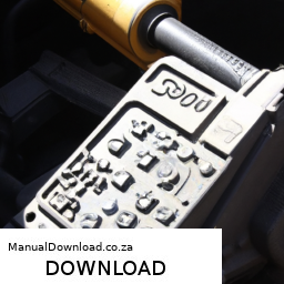
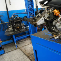
Cleaning the intake manifold on a Citroën C4 2nd generation involves several steps. click here for more details on the download manual…..


    How to do a muffler delete in less than 60 seconds #shorts muffler delete,muffler,how to do a muffler delete,turbo muffler delete,resonator delete,delete,muffler delete sound,bmw e46 muffler …

    how to jumpstart a car with awkward battery position! Citroen C4 4K diy #diytaj #carhacks #howtodoit #easyfix #jumpstart #jumpleads #startingproblem How to jumpstart a car Citroen C4 2011 For …

Here’s a reverse order guide to help you understand the process from the final step back to the beginning:

### 6. Reinstallation
– **Reattach the Intake Manifold**: Carefully position the cleaned intake manifold back onto the engine. Ensure that all gaskets are in place and that there are no obstructions.
– **Reconnect All Lines and Hoses**: Reattach any vacuum lines, electrical connectors, and hoses that were removed during disassembly.
– **Tighten Bolts**: Follow the manufacturer’s specified torque sequence and specifications for the intake manifold bolts to ensure a proper seal.

### 5. Final Checks
– **Reconnect the Battery**: If you had disconnected the battery for safety, reconnect it.
– **Check for Leaks**: Before starting the engine, do a visual inspection to ensure there are no loose connections or visible leaks.
– **Start the Engine**: Turn on the engine and let it idle. Listen for any unusual noises and check for any warning lights on the dashboard.

### 4. Cleaning the Manifold
– **Use Cleaning Solution**: Apply a suitable intake cleaner or throttle body cleaner to the intake manifold using a soft brush or cloth. Pay special attention to carbon deposits and build-up.
– **Rinse and Dry**: After cleaning, rinse the manifold with clean water if necessary and allow it to dry completely before reinstallation.

### 3. Disassembly
– **Disconnect Components**: Remove any components that obstruct access to the manifold, such as the air intake hose, throttle body, and any sensors or electrical connectors.
– **Remove the Intake Manifold**: Unbolt and carefully lift the intake manifold off the engine. Be cautious of any remaining gaskets or debris.

### 2. Preparation
– **Gather Tools and Materials**: Ensure you have the necessary tools (sockets, wrenches, screwdrivers) and cleaning materials (intake cleaner, brushes, rags) ready.
– **Safety Precautions**: Disconnect the battery to prevent any electrical issues and wear protective gear such as gloves and goggles.

### 1. Vehicle Preparation
– **Park the Vehicle Safely**: Ensure the vehicle is parked on a flat surface and is secure. Raise the hood and allow the engine to cool if it was recently running.

By following these steps in reverse order, you can effectively understand the intake manifold cleaning process for a Citroën C4 2nd generation. Always consult the vehicle’s service manual for specific instructionsdownload Citroën C4 2nd Gen workshop manual and safety precautions related to your model.
The clutch master cylinder is a crucial component in the hydraulic clutch system of a vehicle, particularly in manual transmission cars. Its primary function is to convert the mechanical force exerted by the driver’s foot on the clutch pedal into hydraulic pressure. This hydraulic pressure is then transmitted to the clutch slave cylinder, which engages or disengages the clutch, allowing the driver to shift gears smoothly.

The clutch master cylinder consists of a cylindrical housing that contains a piston, seals, and a fluid reservoir. when the driver presses the clutch pedal, the pedal connects to the piston within the master cylinder, causing it to move and compress the hydraulic fluid inside. This movement generates pressure that travels through a series of hydraulic lines to the slave cylinder. The slave cylinder then activates the clutch fork, which either disengages or engages the clutch plate, depending on whether the pedal is pressed or released.

One of the key advantages of a hydraulic clutch system, facilitated by the clutch master cylinder, is its ability to provide a smoother and more consistent pedal feel compared to traditional cable-operated systems. Additionally, it requires less physical effort from the driver, making it more comfortable, especially in stop-and-go traffic. However, like any mechanical component, the clutch master cylinder can wear out or develop leaks, leading to symptoms such as a spongy clutch pedal or difficulty in shifting gears, necessitating timely inspections and potential replacement. Overall, the clutch master cylinder plays a vital role in ensuring the efficient operation of a vehicle’s transmission system.

Download Hyundai R210LC-7 Crawler Excavator Factory Service Repair Manual-

book store
Sure! click here for more details on the download manual…..


    2012 Hyundai ROBEX 210 LC-9 http://www.machineryaccess.com/equipment-for-sale/83452/excavators/hyundai/robex-210-lc-9 Contact Victor L. Phillips Co …

    Hyundai R380LC-9 Excavator Hydraulic Flow Adjustment to the Thumb http://www.sheelysupply.com Procedure to adjust the speed of the the thumb cylinder. Speed up or slow down. Industrial Diesel …

Below are detailed bullet points explaining how to replace the shock mount on a Hyundai R210LC-7 Crawler Excavator, including descriptions of the tools you will need for the job.

### tools and Equipment Needed:

– **Socket Set:**
– A comprehensive socket set (both metric and standard) is essential for removing bolts and nuts. Ensure you have a ratchet and extensions for hard-to-reach areas.

– **Wrenches:**
– A set of adjustable and combination wrenches will help in loosening and tightening bolts that may not be accessible with a socket.

– **Torque Wrench:**
– This tool is crucial for tightening bolts to the manufacturer’s specified torque settings to ensure everything is secure and safe.

– **Pry Bar:**
– A pry bar will assist in removing the old shock mount If it’s stuck or difficult to pull out.

– **Hammer/Mallet:**
– A hammer or rubber mallet can help to gently tap components into place or loosen components without damaging them.

– **Jack and Jack Stands:**
– Use a hydraulic jack to lift the excavator safely. Jack stands are necessary to provide stable support while working under the machine.

– **Safety Gear:**
– Always wear safety glasses, gloves, and steel-toed boots to protect yourself from debris and heavy components.

– **Cleaning Supplies:**
– Rags and cleaning solvent will be needed to clean any dirt or grease from the mounting area before installation.

### Replacement Process:

– **Preparation:**
– Park the excavator on a flat, stable surface and engage the parking brake. Turn off the engine and disconnect the battery to ensure safety.

– **Lifting the Excavator:**
– Use the hydraulic jack to lift the excavator. Secure it with jack stands to prevent any accidental lowering while you work.

– **Accessing the Shock Mount:**
– Locate the shock mount, which is typically positioned near the excavator’s undercarriage or suspension system. Remove any covers or components that obstruct access.

– **Removing the Old Shock Mount:**
– Use the appropriate sockets or wrenches to remove the bolts securing the shock mount. Keep track of the bolts and nuts, as you will need them for the new mount.
If the shock mount is stuck, gently use a pry bar to loosen it without damaging surrounding components.

– **Inspecting Components:**
– Before installing the new shock mount, inspect the surrounding area for wear or damage. Check the condition of the bolts and replace them If necessary.

– **Installing the New Shock Mount:**
position the new shock mount in place, ensuring it aligns correctly with the mounting holes.
– Hand-tighten the bolts to hold the mount in position before fully tightening them.

– **Tightening Bolts:**
– Using a torque wrench, tighten the bolts to the manufacturer’s specified torque settings. This ensures the mount is securely fasteneddownload Hyundai R210LC 7 Crawler Excavator Manual workshop manual and reduces the risk of failure.

– **Cleaning and Final Checks:**
– Clean any excess grease or debris from the area. Double-check that all bolts are tightened and that the shock mount is securely in place.

– **Lowering the Excavator:**
– Carefully remove the jack stands and lower the excavator back to the ground using the hydraulic jack. Once on the ground, remove the jack.

– **Reconnecting the Battery:**
– Reconnect the battery and start the excavator to ensure everything is functioning correctly. Listen for any unusual noises that might indicate an issue.

– **Testing:**
– Conduct a test run of the excavator to ensure the new shock mount is functioning as intended. Monitor for any signs of instability or abnormal vibrations during operation.

### Conclusion:

Replacing the shock mount on a Hyundai R210LC-7 Crawler Excavator requires careful attention to detail and safety. By following the steps outlined and using the proper tools, you can successfully complete the replacement and ensure the excavator operates smoothly. Always refer to the manufacturer’s manual for specific instructions and specifications related to your model.
An antenna is a crucial component of a vehicle’s communication and entertainment systems, serving as a device that transmits and receives radio waves. Typically made from conductive materials, such as metal or copper, antennas are designed to convert electrical signals into electromagnetic waves and vice versa. In modern vehicles, antennas are essential for various functions, including radio broadcasting, GPS navigation, cellular connectivity, and even satellite communications.

The design and placement of antennas can vary significantly depending on their intended use. For instance, traditional radio antennas are often long and slender, protruding from the vehicle’s roof or fenders for optimal signal reception. In contrast, more contemporary vehicles may feature integrated antennas embedded within the rear windshield or front windshield, or even disguised within the vehicle’s body to enhance aesthetics while maintaining functionality.

As technology has advanced, the role of antennas has expanded. Vehicles equipped with infotainment systems now rely on antennas to facilitate streaming music, navigation updates, and hands-free calling via mobile networks. Furthermore, the rise of connected vehicles has led to the development of multi-functional antennas capable of handling various frequencies, thus enabling seamless communication with the Internet of Things (IoT).

In summary, the antenna is a pivotal component that enhances a vehicle’s connectivity and entertainment capabilities, reflecting the growing integration of technology in automotive design.

Download Kawasaki FH721D Engine Factory Service & Work Shop Manual –

get
Windshield repair on a Kawasaki FH721D engine workshop may refer to a process related to repairing a damaged windshield on a vehicle or equipment that utilizes this engine. click here for more details on the download manual…..


    Kawasaki FH721D Kawasaki FH721D 25hp bench test.

    Kawasaki fh721d piston install 25hp John Deere 757

However, it seems that you might be looking for a general guide on how to perform windshield repair, possibly within a workshop setting. Here’s a reverse order explanation of the process:

### Step-by-Step Windshield Repair Process (In Reverse Order)

#### 6. **Curing the Resin**
– Allow the resin to cure as per the product instructions, typically By exposing it to UV light or letting it set for a specified duration.
ensure the repair area is clear of any obstructions during this process.

#### 5. **Finishing Touches**
– After curing, use a razor blade to carefully trim any excess resin that may have seeped out of the crack.
– Clean the area around the repair with a glass cleaner to remove any dust or fingerprints.

#### 4. **Injecting the Resin**
– Use a resin injector tool to inject the repair resin into the damaged area.
ensure that the resin fills the crack completely to eliminate air pockets.

#### 3. **Preparing the Surface**
– Clean the damaged area thoroughly to remove any dirt or debris. Use a glass cleaner and lint-free cloth.
– If necessary, use a drill to create a small entry point at the end of the crack to ensure the resin can be injected effectively.

#### 2. **Assessing the Damage**
– Inspect the crack or chip to determine if it is suitable for repair. Generally, cracks longer than 6 inches or chips larger than a quarter may require replacement instead.
– If the damage is repairable, proceed with the next steps.

#### 1. **Gathering Materials**
– Collect all necessary tools and materials, including:
– Windshield repair kit (resin, injector, curing strips)
– Razor blade
– Glass cleaner
– Lint-free cloth
– Drill (if needed)

### Final Notes
– Always follow safety precautions while working on any repairs.
– If you’re unsure about the repair process or the damage is extensive, consider consulting a professional for assistance.
– Keep in mind that the quality of the repair can vary based on the skill of the person performing itdownload Kawasaki FH721D Engine Work Shop workshop manual 
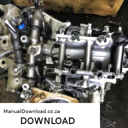
and the extent of the damage.

This reverse order breakdown provides a clear understanding of the windshield repair process, starting from the final steps and working back to the initial preparations.
An exhaust hanger is a crucial component in a vehicle’s exhaust system, designed to support and secure the exhaust pipes and muffler in place. Typically made from rubber, metal, or a combination of both, exhaust hangers are engineered to absorb vibrations and movements generated By the engine and road conditions, thereby mitigating noise and preventing damage to the exhaust system.

The primary function of an exhaust hanger is to maintain the proper alignment of the exhaust system components, ensuring that they do not come into contact with other parts of the vehicle, such as the chassis or suspension. This is vital for preventing wear and tear, which could lead to exhaust leaks or even compromised vehicle performance. The rubber material in many exhaust hangers helps to dampen vibrations, providing a quieter ride and enhancing overall comfort for passengers.

Exhaust hangers come in various shapes and sizes, tailored to fit different vehicle models and exhaust configurations. Over time, they can suffer from wear, cracking, or deterioration due to exposure to heat, moisture, and road grime. Regular inspection of exhaust hangers is essential, as damaged hangers can lead to loose exhaust components, increased noise, and potential damage to the exhaust system, necessitating timely replacement to maintain optimal vehicle performance and safety.

Download Kawasaki FH721V Factory Service & Work Shop Manual –

sale
Repairing the shift detent on a Kawasaki FH721V engine involves several steps, and it’s common to outline procedures in a straightforward manner. click here for more details on the download manual…..


    toro bigdog alpha with kawasaki fr691v 23hp fix tire leak

    Putting pistons in the cylinder, 25 HP Kawasaki FH721V This motor is from a Gravely 260-Z. Because I only honed the cylinders, rather than boring them, I was able to go back with the …

However, since you requested the steps in reverse order, here is an outline of the process starting from the final step to the initial step:

### Reverse Order Steps for Shift Detent Repair:

1. **Reassemble the Engine**:
– Ensure all components are properly fitted back into place. Replace any gaskets or seals that were disturbed during the repair.

2. **Install the Side Cover**:
– Attach the side cover securely, ensuring all screws or bolts are tightened to the specified torque settings.

3. **Reconnect Linkages**:
– Reattach any linkages or cables that were disconnected during the repair process. Ensure they are functioning correctly.

4. **Reinstall the Shift Detent**:
– Place the repaired or new shift detent into its housing, ensuring that it is seated correctly.

5. **Inspect and Replace Springs**:
check the springs associated with the shift detent for wear. Replace them if necessary before installing the detent.

6. **Remove the Side Cover**:
– If not already done, carefully take off the side cover to access the internal components.

7. **Access the Shift Detent Mechanism**:
– Locate the shift detent mechanism within the engine. This may involve removing other components for better access.

8. **Examine Components**:
– Inspect the shift detent, springs, and Related parts for wear, damage, or malfunction. Replace any defective components.

9. **Gather Tools and Parts**:
– Collect necessary tools (like wrenches, screwdrivers, etc.) and replacement parts (detent, springs, gaskets) before starting the repair.

10. **Review Service Manual**:
– Before beginning, consult the Kawasaki FH721V service manual for specific guidelines, torque specifications, and diagrams.

### Important Notes:
– Always ensure safety precautions are taken, such as disconnecting the batterydownload Kawasaki FH721V Work Shop workshop manual 
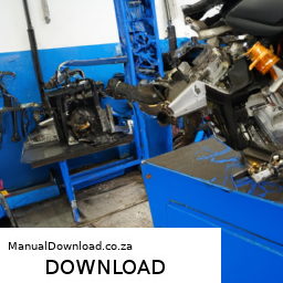
and ensuring the engine is cool before starting work.
– Keep a clean workspace to avoid losing small parts.
– If you’re not familiar with engine repairs, consider seeking help from a professional mechanic or referring to detailed service manuals.

By following these reversed steps, you should have a clearer Understanding of the shift detent repair process for a Kawasaki FH721V engine.
The EGR (Exhaust Gas Recirculation) valve is a crucial component in modern internal combustion engines, primarily designed to reduce nitrogen oxide (NOx) emissions and improve overall engine efficiency. Its main function is to recirculate a portion of the exhaust gases back into the engine’s intake manifold. This process helps lower combustion temperatures, as the reintroduced exhaust gases dilute the incoming air-fuel mixture, effectively reducing the formation of NOx, which is a significant contributor to air pollution and smog.

The EGR valve can be either vacuum-operated or electronically controlled, depending on the vehicle’s make and model. In vacuum-operated systems, the EGR valve opens when a vacuum signal is generated by the engine, allowing exhaust gases to flow into the intake manifold. In contrast, electronically controlled EGR valves utilize sensors and an electronic control unit (ECU) to manage the valve’s operation more precisely, allowing for better control of emissions and engine performance.

A well-functioning EGR valve contributes to the overall efficiency of an engine by enabling better combustion and reducing the likelihood of knocking or pinging. However, over time, the EGR valve can become clogged with carbon deposits, leading to decreased performance, increased emissions, and potential engine issues. Regular maintenance and inspection of the EGR system are essential for optimal engine operation and compliance with emission regulations.

Download 2007 Honda Pilot Repair Manual –

repair manual
Windshield repair on a Honda Pilot can be a straightforward process if you have the right tools and materials. click here for more details on the download manual…..


    Honda J-Series V-tec Solenoid Oil Leak Explained & Fix Spool Valve P3497 P2646 The gaskets: https://www.amazon.com/dp/B08PQNY3DJ/ref=cm_sw_r_as_gl_apa_gl_i_XXJXSP0KNKYCBVN0K9GG?

    2023-2025 Honda Pilot: TIPS AND TRICKS YOU CAN'T MISS New Honda Pilot owner? Let’s dive deep into your SUV! Discover hidden features, maximize your ride, and experience the Pilot …

below is a step-by-step guide with detailed descriptions of each tool you may need for the repair:

– **Windshield Repair Kit**:
– This is the primary tool for repairing chips and cracks in your windshield. A typical kit includes a resin injector, resin, a curing strip, and a razor blade. The resin is specially formulated to fill in the damage and bond the glass together.

– **Resin Injector**:
– This tool is used to inject the repair resin into the chip or crack. It typically features a suction cup base that adheres to the windshield and a plunger mechanism to force the resin into the damaged area.

– **Repair Resin**:
– A clear, liquid substance that fills the chip or crack. The resin is designed to bond with the glass and restore its structural integrity. Make sure to choose a resin that is compatible with your windshield and is suitable for the type of damage you are repairing.

– **Curing Strips**:
– These are thin, clear strips that are applied over the resin after it has been injected. They help to keep the resin in place while it cures and also provide a smooth finish to the repair.

– **Razor Blade or Scraper**:
– This tool is used to remove any excess resin after it has cured, ensuring a smooth and unobtrusive finish. A single-edge razor blade works best for scraping the surface of the windshield without causing further damage.

– **Drill with a Diamond-Tipped Bit (optional)**:
– If the chip is particularly deep, you may need a drill to create a small hole at the center of the damage. This allows for better resin penetration. A diamond-tipped bit is recommended for glass to avoid cracking the windshield further.

– **Vacuum Pump (optional)**:
– Some advanced repair kits include a vacuum pump to remove air from the chip before injecting the resin. This can help ensure that the resin fills the entire cavity and improves the quality of the repair.

– **Paper Towels or Cloth**:
– Used for cleaning the area around the damage before starting the repair. Keeping the surface clean is crucial for proper adhesion of the resin.

– **Gloves**:
– Wearing gloves is essential to protect your hands from the resin, which can be sticky and difficult to remove.

– **Safety Glasses**:
– Always wear safety glasses to protect your eyes while working on the windshield, especially when cutting or drilling.

### Repair Process:

– **Prepare the Area**:
– Clean the area around the chip or crack with paper towels or cloth to remove dirt and debris. This ensures the resin adheres properly.

– **Position the Resin Injector**:
– Place the resin injector over the chip or crack, making sure it’s centered. Secure it in place using the suction cup base.

– **Inject the Resin**:
– Pull the plunger to create a vacuum, which will help draw the resin into the damaged area. Once you’ve created a vacuum, release the plunger to let the resin fill the chip or crack. Repeat this process if necessary to ensure complete fill.

– **Apply Curing Strip**:
– Once the resin is injected, place the curing strip over the area to keep the resin in place while it cures.

– **Cure the Resin**:
– Allow the resin to cure according to the manufacturer’s instructions. This usually takes a few minutes, depending on the type of resin used.

– **Remove Excess Resin**:
– After the resin has cured, use the razor blade or scraper to gently remove any excess resindownload Honda Pilot workshop manual and level the surface with the windshield.

– **Final Clean**:
– Wipe the area clean and inspect the repair. The chip should be less noticeable, and the structural integrity of the windshield should be restored.

Following these steps and using the appropriate tools will help you successfully repair a windshield chip or crack on your Honda Pilot. Always consult your vehicle’s manual or a professional if you’re unsure about any part of the process.
The turn signal switch, often referred to as the indicator switch or turn signal lever, is a crucial component in a vehicle’s steering column that facilitates the activation of turn signals or indicators. This device enables drivers to communicate their intention to turn or change lanes to other road users, thereby promoting safety and reducing the likelihood of accidents. Typically located on the left side of the steering column, the turn signal switch is designed for easy access, allowing drivers to operate it with minimal distraction.

When the driver activates the switch, it completes an electrical circuit that powers the turn signal lights located on the front, rear, and sometimes the sides of the vehicle. The switch usually operates in a “stick” style, where the driver pushes it up to signal a right turn and down to indicate a left turn. In many modern vehicles, the turn signal switch also integrates other functionalities, such as the windshield wiper controls, high beam activation, and even cruise control settings.

In addition to its primary function, the turn signal switch is designed with an automatic cancellation feature. This means that once the turn is completed, the switch will return to its neutral position, turning off the signal lights. This component is typically made from durable materials to withstand frequent use and is engineered to operate reliably over the lifespan of the vehicle. Regular maintenance and timely replacement of a malfunctioning turn signal switch are essential for ensuring the effectiveness of a vehicle’s signaling system, which plays a vital role in road safety.

Download 1999 Mazda Miata Service & Repair Manual Software –

book shop
Reconditioning the gearbox of a Mazda Miata is a detailed process that requires precision, the right tools, and a good understanding of the vehicle’s mechanics. click here for more details on the download manual…..


    MX5 MIATA FRONT WHEEL BEARING mx5 #miata Change your MX5 Miatas front wheel bearing with ease yourself and here is how re-upload due to copyright claim …

    The $38K Mazda MX-5 Miata is the definition of FUN. 😄

Below is a comprehensive list of the tools and steps involved in reconditioning a Mazda Miata gearbox.

### Tools and Equipment

– **Mechanic’s Tool Set**
– **Socket Set**: A complete set of metric sockets (including deep sockets) is essential for removing various bolts and nuts.
– **Wrenches**: Open-end and box-end wrenches in various sizes will help access tight spots.
– **Torque Wrench**: Ensures that bolts are tightened to manufacturer specifications, which is critical for the gearbox’s performance.

– **Screwdrivers**
– **Flathead and Phillips Screwdrivers**: Useful for removing various screws and clips throughout the gearbox assembly.

– **Pliers and Cutters**
– **Needle-Nose Pliers**: Helpful for gripping small components and removing retaining clips.
– **Wire Cutters**: For cutting any retaining wires or clips that may be in the way.

– **Gearbox Oil**
– **Recommended Gear Oil**: Ensure you have the correct type and amount of gearbox oil for refill after reconditioning.

– **Sealant and Gasket Maker**
– **RTV Silicone Adhesive**: For sealing any joints or areas that may require a new seal after reconditioning.

– **Cleaning Supplies**
– **Degreaser**: For cleaning components before reassembly.
– **Rags and Brushes**: For manual cleaning of parts.

– **Measuring Tools**
– **Caliper**: For measuring clearances and wear on gearbox components.
– **Feeler Gauges**: To check tolerances between gears and bearings.

– **Inspection Tools**
– **Magnetic Pick-Up Tool**: To retrieve dropped components or debris from hard-to-reach areas.
– **Flashlight or Inspection Light**: To illuminate dark areas within the gearbox for better visibility.

– **Specialty Tools**
– **Bearing Puller/Installer**: For safely removing and installing bearings.
– **Clutch alignment Tool**: To ensure proper alignment during reassembly if the clutch is involved.
– **Flywheel Holder Tool**: To hold the flywheel in place when tightening bolts.

– **Safety Gear**
– **Safety Glasses**: To protect your eyes while working.
– **Gloves**: To keep your hands safe from sharp edges and chemicals.

### Steps for Gearbox Reconditioning

– **Preparation**
– Ensure you have a clean, organized workspace with sufficient lighting.
– Gather all tools and components necessary for the job.

– **Vehicle Preparation**
– Disconnect the battery to prevent any electrical issues.
– Lift the vehicle using a hydraulic jack and secure it with jack stands.

– **Remove the Gearbox**
– Detach the driveshaft from the rear differential.
– Disconnect the shifter linkage and any electrical connections.
– Unbolt the gearbox from the engine and carefully lower it out of the vehicle.

– **Disassemble the Gearbox**
– Carefully remove the gearbox housing bolts using the socket set.
– Separate the gearbox halves and inspect for damage.
– Take note of the arrangement of gears, bearings, and other internal components for reassembly.

– **Inspect Components**
– Examine all gears and bearings for wear or damage.
– Measure tolerances using calipers and feeler gauges to identify parts that need replacement.

– **Clean Components**
– Use degreaserdownload Mazda Miata workshop manual and brushes to clean all parts thoroughly.
– Inspect cleaned parts for any remaining wear or damage.

– **Replace Worn Parts**
– Replace bearings, seals, and any damaged gears with new components.
– Ensure that all replacement parts meet OEM specifications.

– **Reassemble the Gearbox**
– Follow the reverse order of disassembly, ensuring that all components are properly aligned.
– Use a torque wrench to tighten bolts to the specified torque settings.
apply gasket maker where needed to ensure a proper seal.

– **Reinstall the Gearbox**
– Lift the gearbox back into position under the vehicle.
– Reconnect the shifter linkage, electrical connections, and driveshaft.
– Bolt the gearbox back onto the engine securely.

– **Fill with Gear Oil**
– Use the recommended gearbox oil to fill the transmission through the fill plug.
– Ensure the oil level is correct according to specifications.

– **Final Checks**
– Reconnect the battery.
– Start the vehicle and allow it to warm up.
– Check for leaks and ensure the gearbox operates smoothly through all gears.

– **Test Drive**
– Take the vehicle for a test drive to confirm that the gearbox is functioning properly.
– Listen for any unusual noises and check for any signs of leakage.

### Conclusion

Reconditioning the gearbox of a Mazda Miata requires careful attention to detail and the right tools. Following each step methodically will ensure that the gearbox operates efficiently and reliably after reconditioning. Always refer to the vehicle’s service manual for specific torque specifications and detailed assembly instructions.
A door lock is a critical component of a vehicle’s security and safety systems, designed to prevent unauthorized access and ensure the safety of occupants and their belongings. Typically located on each door, the door lock mechanism can vary in design and operation, but its primary function remains consistent: to secure the vehicle’s doors when closed and to provide a means of entry when the driver or passengers wish to access the interior.

Modern door locks often feature electronic mechanisms that are integrated with the vehicle’s central locking system, allowing for simultaneous locking and unlocking of all doors with the push of a button on the key fob or through the vehicle’s interior controls. Many contemporary vehicles also incorporate smart technology, enabling features such as keyless entry or remote access, where the door locks can be engaged or disengaged without physically using a key.

There are several types of door locks, including traditional mechanical locks, deadbolts, and electronic locks. Mechanical locks rely on a physical key to operate, while electronic locks may use a keypad, RFID technology, or biometric scanning for added security. Additionally, door locks often include features such as child safety locks, which prevent rear doors from being opened from the inside, enhancing the safety of young passengers.

Overall, door locks are essential for vehicle security, providing peace of mind to owners and ensuring that the car’s interior remains protected from theft or intrusion. They are a vital part of a vehicle’s overall functionality, combining security, convenience, and safety in their design.

Download Deutz 2013 2v Engine Spare Parts Catalogue Manual –

get
Repairing the suspension crossmember on a Deutz 2V engine can seem daunting, especially if you have little mechanical experience. click here for more details on the download manual…..


    Deutz TCD2012 L04 2V Dyno run of reconditioned Diesel engine Deutz TCD2012 L04 2V Please visit us on wibako.eu.

    Ozka Front Tractor Tires – Review and TEST DRIVE – Deutz Fahr Ӧzka KNK 33 front tractor tires, initial review and test drive. These tires made by @OZKATyre were put on the Deutz Fahr D4506 …

However, I’ll break it down into simple steps. Keep in mind that working on machinery can be dangerous, so always prioritize safety and consult a professional if you’re unsure about any step.

### What is a Suspension Crossmember?

The suspension crossmember is a structural piece that supports the vehicle’s suspension system. It connects the left and right sides of the suspension and helps to stabilize the vehicle.

### Tools and Materials Needed

1. **Basic Tools**:
– Wrenches and sockets (various sizes)
– Screwdrivers
– Pliers
– Hammer
– Jack and jack stands (for lifting the vehicle)
– Safety goggles and gloves

2. **Replacement Parts** (if necessary):
– New crossmember or repair parts
– Bushings or mounts (if needed)

3. **Cleaning Supplies**:
– Degreaser
Rags or paper towels

### Step-by-Step Guide to Repair the Suspension Crossmember

#### Step 1: Safety First
– **Park the Vehicle**: Ensure the vehicle is on a flat surface.
– **Turn Off the Engine**: Make sure the vehicle is turned off and cool.
– **Wear Safety Gear**: Put on your safety goggles and gloves to protect yourself.

#### Step 2: Lift the Vehicle
– **Use the Jack**: Place the jack under the vehicle’s frame and lift it.
– **Secure with Jack Stands**: Once elevated, place jack stands under the vehicle to secure it. Never work under a vehicle supported only by a jack.

#### Step 3: Locate the Crossmember
– **Identify the Part**: The suspension crossmember is usually located near the front of the vehicle, connecting the left and right suspension components.

#### Step 4: Inspect the Crossmember
– **Check for Damage**: Look for any visible cracks, rust, or broken parts. If the crossmember is damaged, it may need to be replaced.

#### Step 5: Remove the Crossmember
– **Loosen Bolts**: Using the appropriate wrench or socket, loosen and remove the bolts that hold the crossmember in place. Keep track of the bolts and nuts as you will need them later.
– **Support the Suspension**: If the crossmember is holding any suspension components, you may need to support them temporarily with a jack or blocks.

#### Step 6: Clean the Area
– **Remove Old Grease and Dirt**: Use a degreaser and Rags to clean the area around the crossmember. This will make it easier to install the new part and check for other potential issues.

#### Step 7: Install the New Crossmember
– **Position the New Part**: Align the new or repaired crossmember where the old one was located.
– **Secure with Bolts**: Hand-tighten the bolts first, then use your wrench to secure them fully. Make sure everything is aligned properly.

#### Step 8: Reassemble Any Removed Components
– **Reconnect Suspension Parts**: If you had to disconnect any parts, reattach them securely.

#### Step 9: Lower the Vehicle
– **Remove Jack Stands**: Carefully take out the jack sdownload Deutz 2v Engine ue workshop manualtands and lower the vehicle back to the ground using the jack.

#### Step 10: Test the Repair
– **Check Everything**: Before driving, double-check that all bolts are tight and that nothing is loose.
– **Take a Test Drive**: Go for a short drive to ensure everything feels stable and there are no unusual noises.

### Final Tips
– **Consult the Manual**: If you have access to the service manual for the Deutz engine, refer to it for specific instructions and torque specifications.
– **Ask for Help**: If at any point you feel unsure, don’t hesitate to ask someone with more mechanical experience or consult a professional mechanic.

By following these steps carefully, you can successfully repair the suspension crossmember on a Deutz 2V engine. Remember, safety is paramount, so take your time and don’t rush through any steps!
The hood, also known as the bonnet in some regions, is a vital component of a vehicle that serves several important functions. Located at the front of the car, the hood provides access to the engine compartment, which houses the engine and various other mechanical systems, such as the battery, cooling system, and electrical wiring. Typically made from materials like steel, aluminum, or composite materials, the hood is designed to be both lightweight and durable, helping to protect the engine from external elements while also contributing to the vehicle’s overall aerodynamics.

In terms of design, hoods can vary significantly depending on the make and model of the vehicle. Some hoods feature vents or scoops to improve airflow to the engine or enhance cooling, while others may have a more streamlined appearance for aesthetic purposes. The hood is often equipped with a latch mechanism that secures it in place while driving, ensuring that it remains closed during operation. Safety is also a major consideration; modern hoods are designed to crumple in the event of a collision, reducing the risk of injury to pedestrians.

In addition to its practical uses, the hood plays a significant role in the vehicle’s overall appearance, contributing to its style and character. Custom hoods are popular among car enthusiasts, allowing for personalization and performance enhancements. Whether for maintenance, repairs, or aesthetic appeal, the hood is an essential element of automotive design that combines functionality with style.

Download 2016 BMW 428i xDrive (F36) 4 Series Gran Coupe OEM Download Service & Repair Manual Software –

discount
Repairing the hydraulic clutch on a BMW 428i xDrive F36 Gran Coupe involves several steps. click here for more details on the download manual…..


    BMW 428i gran coupe (F36) cold start

    BMW 435i WITH SPACERS 15m & 20m #bmw #bmwnation #bmw4series #car #bmwmpower #automobile #reac…

Below are the steps presented in reverse order, starting from the completion of the repair and working back to the initial preparations:

### 10. **Reassemble Components:**
– Reinstall any covers or panels that were removed to access the clutch system.
– Ensure all fasteners are tightened to the manufacturer’s specifications.

### 9. **Bleed the clutch System:**
– Use a brake bleeder tool or manual method to bleed the hydraulic system, ensuring all air is removed.
– Check the fluid level and top up as necessary with the recommended brake fluid.

### 8. **Reconnect the clutch Line:**
– If you disconnected the hydraulic line, carefully reconnect it, ensuring a secure fit and no leaks.

### 7. **Replace the clutch Master/Slave Cylinder:**
– If necessary, remove the old master cylinder or slave cylinder and replace it with the new OEM part.
– Secure the new component in place, making sure all connections are tight.

### 6. **Access the Hydraulic Components:**
– Depending on the model year and specific setup, you may need to remove the driver’s side footwell cover to access the clutch master cylinder.

### 5. **Remove the Old Hydraulic Fluid:**
– Use a siphon or turkey baster to remove old hydraulic fluid from the reservoir.
– Dispose of the old fluid in accordance with local regulations.

### 4. **Prepare the Workspace:**
– Gather all necessary tools and materials, including new hydraulic fluid, a wrench set, a brake bleeder tool, and any replacement parts.
– Ensure your vehicle is securely parked and on a flat surface.

### 3. **Disconnect the Battery:**
– Disconnect the negative terminal of the battery to prevent any electrical issues during the repair process.

### 2. **Identify the Problem:**
– Diagnose the issue with the clutch, confirming whether it is a fluid leak, air in the system, or a faulty master/slave cylinder.

### 1. **Gather technical Specifications:**
– Obtain the service manual for the BMW 428i xDrive F36, which includes specifications, torque settings, and diagrams for reference throughout the repair process.

### Additional Tips:
– Always wear safety gear, including gloves and goggles, when working with hydraulic fluids.
– Make sure to work in a well-ventilated area to avoid inhaling fumes from the brake fluid.
– If you’re unsure about any step, consult a professional mechanic or refer to repair forums specific to BMW vehicles.

Following these steps in reverse will help ensure that the hydraulic clutch repair is done systematicallydownload BMW 428i xDrive F36 4 Gran Coupe OEM workshop manual and effectively.
A car Jack is a mechanical device designed to lift a vehicle off the ground, allowing for various maintenance and repair tasks to be performed safely and efficiently. This essential tool is crucial for changing tires, inspecting undercarriage components, or performing brake work, among other automotive tasks.

Car jacks come in several types, with the most common being the hydraulic jack, scissor jack, and floor jack. Hydraulic jacks utilize hydraulic fluid to lift heavy loads and are known for their ease of use and efficiency. They typically feature a piston mechanism that allows for significant lifting power with minimal effort. Scissor jacks are manual devices that operate on a simple lever and screw mechanism, which expands and contracts to lift the car. They are often included with vehicles as part of the tire-changing kit due to their compact size and lightweight design. Floor jacks, on the other hand, are more robust and feature a wide base and large wheels, making them stable and mobile while providing substantial lifting capabilities.

Safety is paramount when using a car jack. It’s critical to ensure that the Jack is placed on a solid, level surface and that the vehicle is in Gear or has its parking brake engaged to prevent it from rolling. Additionally, Jack stands should be used to secure the vehicle once it is elevated, as relying solely on the Jack can be dangerous due to potential mechanical failure. Overall, a car Jack is an indispensable tool for both professional mechanics and DIY enthusiasts, facilitating necessary repairs while ensuring safety and efficiency.

Download Lycoming 0-235-C n 0-290-D aircraft engine Parts manual PC- –

book store
Adjusting the parking brake on a Lycoming O-235-C and O-290-D aircraft engine is a straightforward process, but it requires careful attention to detail to ensure safety and proper functioning. click here for more details on the download manual…..


    世界一周を小型飛行機で軽々と出来るフライトシミュレーター 🛩🌥🌎… ミニチュア版の世界を飛び回り、様々なプロジェクトに荷物を届ける小さなゲーム。 気に入って頂けましたら、是非とも …

Here’s a simple guide to help you understand the steps involved in adjusting the parking brake:

### Tools and materials Needed:
– **Wrench or socket set**: To adjust the brake cable.
– **Screwdriver**: Depending on the type of fasteners used.
– **Safety goggles**: To protect your eyes.
– **Torque wrench**: If specified in the maintenance manual.

### Steps to Adjust the Parking Brake:

1. **Safety First**:
– Ensure the aircraft is parked on a level surface.
– Set chocks behind the wheels to prevent the aircraft from moving.
– Wear safety goggles to protect your eyes from debris.

2. **Locate the Parking Brake Control**:
– The parking brake control is usually found near the pilot’s seat. It can be a lever or a pedal that you push down to engage the brake.
– Familiarize yourself with how it operates before making any adjustments.

3. **Check the Current Brake Operation**:
– Before adjusting, test the parking brake by engaging it and attempting to move the aircraft slightly.
– If the aircraft rolls or the brake feels loose, it may need adjustment.

4. **Find the Brake Cable**:
– Locate the brake cable that connects the parking brake control to the braking mechanism. This cable is typically routed under the floor or behind the panel.

5. **Adjust the Brake Cable**:
– Look for an adjustment nut on the brake cable. This is often found near the parking brake control or at the brake mechanism itself.
– Use a wrench to loosen the locknut (if present) on the adjustment nut.
– Turn the adjustment nut clockwise to tighten the cable (which increases brake tension) or counterclockwise to loosen it (which decreases brake tension).
– Make small adjustments and check the brake operation after each adjustment.

6. **Test the Brake Again**:
– After making adjustments, re-engage the parking brake and test it again by trying to push the aircraft.
– Repeat the adjustment if necessary until the brake holds the aircraft securely when engaged.

7. **Secure All Components**:
– Once satisfied with the brake adjustment, make sure to tighten the locknut to secure the adjustment.
– Double-check that all tools and materials are removed from the area.

8. **Record the Maintenance**:
– It’s a good practice to document any adjustments made to the parking brake in the aircraft’s maintenance log for future reference.

### Final Thoughts:
Adjusting the parking brake is a critical maintenance task that ensures your aircraft is safedownload Lycoming 0 235 C n 0 290 D aircraft engine PC workshop manual and secure when parked. Always consult the aircraft’s maintenance manual for specific instructions and torque specifications, as there may be slight variations between different models. If you are unsure about any step, consider seeking assistance from a qualified mechanic.
The cooling fan is a critical component in an automobile’s cooling system, primarily designed to regulate the engine’s temperature and prevent overheating. Positioned typically in front of the radiator, the cooling fan plays a vital role in maintaining optimal engine performance, especially during low-speed driving or when the vehicle is stationary.

When an internal combustion engine operates, it generates a significant amount of heat. The cooling system, which includes coolant fluid, the radiator, water pump, and thermostat, works to dissipate this heat. However, during certain conditions—like idling in traffic or when driving at slow speeds—the airflow through the radiator can be insufficient. This is where the cooling fan comes into play.

The cooling fan is usually electric or belt-driven. Electric fans are more common in modern vehicles due to their efficiency and the ability to operate independently of the engine speed. When the engine temperature rises above a certain threshold, a temperature sensor triggers the fan to turn on, pulling air through the radiator to enhance heat dissipation. Conversely, when the temperature drops, the fan may switch off to save energy.

In addition to engine cooling, the fan can also assist in cooling the air conditioning condenser, ensuring optimal performance of the vehicle’s climate control system. A malfunctioning cooling fan can lead to engine overheating, reduced efficiency, and potential engine damage, highlighting its importance in vehicle maintenance and performance. Regular checks and prompt repairs of the cooling fan are essential to ensure a vehicle operates smoothly and efficiently.

Download 1982 BMW 732i (E23) 7 Series OEM Download Service & Repair Manual Software –

online
To check the engine light on a BMW 732i E23, you’ll want to follow these steps in reverse order: ### Step 6: **Review Diagnostic Codes** – After the codes have been retrieved, analyze them to understand what issues are present. click here for more details on the download manual…..


    How to: BMW E23 7 Series Power Steering Fluid and Filter Replacement How to replace the power steering fluid and fluid filter on a BMW E23. A similar procedure may also apply to other BMW models of …

    Bmw E23 745i project car! Electrical problem found! This might be really bad? P1 Mail me stuff: WarpDriveM (P.O. Box ) Postfach 1107 67583 Guntersblum Buy merch here: https://warpdrivem.com/shop Use my …

To check the engine light on a BMW 732i E23, you’ll want to follow these steps in reverse order:

### Step 6: **Review diagnostic Codes**
– After the codes have been retrieved, analyze them to understand what issues are present. You can refer to a BMW service manual or an online database to decode the meanings.

### Step 5: **Turn Off the Ignition**
– Once you have finished retrieving and recording the codes, turn off the ignition to complete the diagnostic process.

### Step 4: **Connect the diagnostic Tool**
– Use an OBD-I (On-Board Diagnostics) scanner compatible with BMW vehicles or a specific BMW diagnostic tool. Connect it to the diagnostic port, typically located under the dashboard near the steering column.

### Step 3: **Prepare for Diagnostics**
– Ensure the car is in a safe, stationary position. Turn the ignition key to the “ON” position without starting the engine. This will power up the onboard computer.

### Step 2: **Locate the diagnostic Connector**
– Find the diagnostic connector in the vehicle. For the BMW 732i E23, this is often found beneath the dashboard on the driver’s side.

### Step 1: **Identify the check Engine Light Issue**
– Before initiating diagnostics, observe the check engine light on the dashboard. Note any patterns (steady or blinking)download BMW 732i E23 7 OEM workshop manual and when it activates (e.g., during acceleration, idling, etc.).

By following these steps in reverse, you can effectively check the engine light on a BMW 732i E23. If you encounter specific codes or issues, further troubleshooting or repairs may be necessary.
A drive shaft is a crucial component in a vehicle’s drivetrain system, responsible for transferring torque and rotational energy from the engine to the wheels. Typically made from materials such as steel or aluminum for strength and durability, the drive shaft is designed to withstand the stresses and strains associated with high-speed rotation and varying loads.

The primary function of the drive shaft is to connect the output of the transmission to the differential, which ultimately powers the wheels. In rear-wheel drive vehicles, the drive shaft runs from the transmission at the front of the vehicle to the rear differential. In all-wheel and four-wheel drive systems, multiple drive shafts may be employed to distribute power to both the front and rear wheels, ensuring better traction and handling.

Drive shafts come in various designs, including single-piece and multi-piece configurations, depending on the vehicle’s length and design. They often incorporate universal joints or constant velocity joints, which allow for flexibility and accommodate changes in angle as the suspension moves.

Regular maintenance of the drive shaft is essential, as wear and tear can lead to vibrations, noise, or even failure, which can compromise vehicle safety and performance. Overall, the drive shaft plays a vital role in delivering power efficiently and ensuring a smooth driving experience.