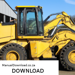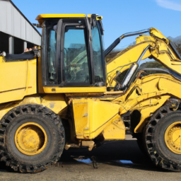
Adjusting the gear ratio on a JCB 406 or 409 Wheel Loading Shovel is a complex process that involves several steps and requires specialized tools and knowledge. click here for more details on the download manual…..
How to operate your JCB Compact Wheel Loader For more information please follow the link below: https://www.jcb.com/en-gb/products/wheel-loaders Get to know your compact …
2000 JCB 409B wheel loader for sale at auction | bidding closes May 7, 2019 View details and pictures — and place your bid at …
Here’s a detailed breakdown of the tools needed and the process involved:
### Tools Required:
– **Torque Wrench**:
– Used to apply a specific amount of torque to fasteners, ensuring they are tightened to the manufacturer’s specifications.
– **Socket Set**:
– A variety of sockets (including deep sockets) to fit different bolt sizes on the wheel loader. Ensures that you can access and remove the necessary components.
– **Wrenches**:
– Adjustable and fixed wrenches to handle various nuts and bolts that may not be accessible with sockets.
– **Pliers**:
– For gripping, twisting, and cutting any wiring or small components as needed during adjustment.
– **Screwdrivers**:
– Both flathead and Phillips to remove or adjust any covers or components that may obstruct access to the gear components.
– **Jack and Stands**:
– To safely lift and secure the wheel loader before beginning work on the undercarriage.
– **Oil Drain Pan**:
– For catching any fluids that may need to be drained during the adjustment process.
– **Measuring Tools**:
– Calipers or a micrometer to measure gear components for precision adjustments.
– **Service Manual**:
– The vehicle’s specific manual provides diagrams and specifications for gear ratios and adjustment procedures.
### Adjustment Process:
– **Safety First**:
– Engage the parking brake and ensure the machine is on a flat surface. Use wheel chocks for additional safety. Wear protective gear including gloves and safety glasses.
– **Prepare the Machine**:
– Use a jack to lift the front of the loader. Secure it with jack stands to prevent it from falling during the adjustment.
– **Drain Fluids**:
– If necessary, drain the transmission or differential fluid into an oil drain pan to prevent spills and make it easier to access the components.
– **Remove Covers**:
– Use screwdrivers and wrenches to remove any covers or shields that protect the gear assembly. This may include side panels or undercarriage covers.
– **Inspect current Gear Ratio**:
– Before making adjustments, measure the current gear ratio by checking the size of the gear teeth and their arrangement. compare these measurements with those provided in the service manual.
– **Adjust Gear Components**:
– Depending on the design, you might need to replace gears or adjust the alignment of the existing gears. This could involve loosening bolts with a torque wrench or socket and repositioning gears according to the desired ratio.
– **Reassemble Components**:
– Once adjustments are made, carefully reassemble any removed components. Use the torque wrench to ensure bolts are tightened to the manufacturer’s specifications.
– **Refill Fluids**:
– Refill the transmission or differential with the appropriate type and amount of fluid, as specified in the service manual.
– **Test the Adjustment**:
– Start the machine and conduct a test run. Pay attention to how the machine operates under load to ensure the new gear ratio is functioning as intended.
– **Final Inspection**:
– After testing, inspect all components for any signs of leaks or abnormal wear. Ensure all tools are removed from the work area and that the machine is in a safe, operable condition.
### Conclusion:
Adjusting the gear ratio on a JCB 406 or 409 Wheel Loading Shovel requires careful attention to detail, the right tools, and a thorough understanding of the machinery. always refer to the manufacturer’s service manual for specific instructions and safety precautions. If uncertain, it’s advisable to consult with a professional technician.
The emission control valve is a critical component of a vehicle’s emission control system, which is designed to reduce the release of harmful pollutants into the atmosphere. This valve plays a significant role in managing the flow of gases and vapors from the fuel system and the engine, ensuring that emissions comply with regulatory standards.
Typically found in systems such as the Evaporative Emission Control System (EVAP), the emission control valve helps prevent the escape of fuel vapors from the fuel tank into the atmosphere. It operates by controlling the flow of these vapors to the engine, where they can be burned during the combustion process instead of being released into the environment. This not only helps reduce hydrocarbon emissions but also improves fuel efficiency.
The emission control valve can be electronically or mechanically operated. In modern vehicles, it is often controlled by the engine control unit (ECU), which monitors various parameters such as engine temperature and pressure to optimize performance. When the engine is running, the valve opens and closes at specific intervals, allowing for the effective recycling of fuel vapors and maintaining optimal air-fuel ratios.
Failure of the emission control valve can lead to increased emissions, reduced engine performance, and can trigger warning lights on the dashboard. Regular maintenance and timely replacement of a faulty valve are essential for ensuring compliance with environmental regulations and for the overall health of the vehicle’s engine.