Download 2005 Mercedes-Benz G-Class G400 Cabrio (W463) OEM Download Service & Repair Manual Software –

service
Repairing the shift interlock on a Mercedes-Benz G-Class G400 Cabrio (W463) involves several steps that require careful attention to detail. click here for more details on the download manual…..


    Is it a bad idea to buy a used Mercedes G W463? 5 reasons to buy and not to buy Mercedes G-Klasse W463.

    Fuse box location and diagrams: Mercedes-Benz G-Class (W463) See more on our website: https://fuse-box.info/mercedes-benz/mercedes-benz-g-class-w463-fuses-and-relay Fuse box diagram …

The shift interlock system is designed to prevent the driver from shifting out of park without pressing the brake pedal. If this system malfunctions, it can prevent the vehicle from starting or shifting gears properly. Below is a detailed guide on how to repair the shift interlock system.

### Tools and Materials Needed
1. **Tools:**
– Screwdrivers (Phillips and flathead)
– Torx screwdriver set
– Socket set (including extensions)
– Pliers
trim removal tools
– Multimeter (for testing electrical components)

2. **Materials:**
– Replacement parts (if needed, such as the interlock solenoid)
– Electrical connectors (if damaged)
– Lubricant (for moving parts)

### Step-by-Step Repair Process

#### 1. Safety Precautions
– **Disconnect the Battery:** Before starting any work, disconnect the negative terminal of the battery to prevent electrical shorts or accidental airbag deployment.

#### 2. Access the Shift Interlock
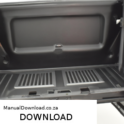
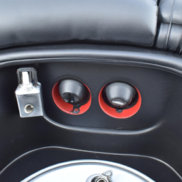
– **Remove the Center Console:**
– Use trim removal tools to carefully pry up the center console trim surrounding the gear shifter. Be cautious to avoid damaging clips.
– Remove screws or bolts holding the center console in place using the appropriate screwdriver or socket. Keep track of all screws and components removed.
– Gently lift the center console to expose the shifter assembly and wiring underneath.

#### 3. Inspect the Shift Interlock Mechanism
– **Locate the Shift Interlock Solenoid:**
– The shift interlock solenoid is typically mounted near the gear shifter assembly. Look for a small cylindrical component connected to the shifter mechanism.

– **Check for Damage:**
– Inspect the solenoid for any visible signs of damage or wear. Look for corrosion, broken wires, or mechanical obstruction.

– **Test the Solenoid:**
– Using a multimeter, check the solenoid for continuity. If there is no continuity, the solenoid may need to be replaced.

#### 4. Repair or Replace Components
– **Repairing the Shift Interlock:**
– If the solenoid is operational but not functioning due to obstruction, clean any debris or lubrication that may be affecting its operation.
– Ensure that the shift interlock lever is moving freely and not obstructed by other components.

– **Replacing the Solenoid:**
– If the solenoid is defective, carefully disconnect the wiring harness by releasing any clips or connectors.
– Remove the solenoid from its mounting bracket, noting how it is installed for proper reassembly.
– Install the new solenoid by reversing the removal steps and reconnecting the wiring harness securely.

#### 5. Reassemble the Center Console
– **Reinstall the Center Console:**
– Carefully position the center console back into place, ensuring that all clips and mounts are aligned correctly.
– Secure the center console with screws or bolts removed earlier.
– Replace any detailed steps, you can successfully diagnose and repair the shift interlock system, ensuring your vehicle operates safely and efficiently. If you encounter significant issues or are unsure about specific components, it’s advisable to consult a professional mechanic or refer to the vehicle’s service manual for further guidance.
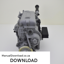
The Mass Airflow Sensor (MAF) is a critical component in an internal combustion engine’s air intake system. Its primary function is to measure the amount of air entering the engine, which is essential for optimizing the air-fuel mixture. By providing accurate airflow data to the Engine Control Unit (ECU), the MAF sensor helps ensure that the engine operates efficiently and effectively, balancing performance, fuel economy, and emissions.

Typically located between the air filter and the intake manifold, the MAF sensor can utilize various technologies, such as hot wire, hot film, or vane types. The hot wire MAF, for instance, consists of a thin wire heated by an electrical current. As air flows over the wire, it cools down; the ECU then calculates the airflow based on the amount of current needed to maintain the wire’s temperature. This measurement is crucial because the engine relies on precise air intake data to adjust the fuel injection accordingly.

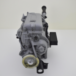
A malfunctioning MAF sensor can lead to various issues, including poor engine performance, rough idling, increased emissions, and reduced fuel efficiency. Common symptoms of MAF sensor problems may include check engine lights, stalling, or hesitation during acceleration. Regular maintenance and inspection of this component are vital for maintaining an engine’s overall health and performance.

Download 1991 Mercedes-Benz G-Class G290GD (W460/W461) OEM Download Service & Repair Manual Software –

book store
Replacing a serpentine belt on a Mercedes-Benz G-Class G290GD (W460/W461) can be done with some basic tools and a little patience. click here for more details on the download manual…..


    2013 Mercedes Benz G Class – G 63 AMG WDCYC7DF2DX210284 Although every reasonable effort has been made to ensure the accuracy of the information contained in …

Here’s a step-by-step guide to help you through the process:

### Tools and Materials Needed:
– New serpentine belt (make sure it’s the right size for your model)
– Socket wrench set
– Ratchet and socket (typically 10mm or 13mm)
– A belt tensioner tool (or a long wrench)
– Pliers (optional)
– A flashlight (for better visibility)
– Safety gloves and goggles (for protection)

### Step-by-Step Instructions:

1. **Safety First**:
– Park the vehicle on a flat surface and turn off the engine.
– Engage the parking brake to prevent any movement.
– If the engine is hot, allow it to cool down before starting.

2. **Locate the Serpentine Belt**:
– Open the hood and locate the serpentine belt. It’s a long rubber belt that wraps around several pulleys, including the alternator, power steering pump, and air conditioning compressor.

3. **Check the Belt Routing**:
– Before removing the belt, take a picture of how it’s routed around the pulleys. this will help you install the new belt correctly.

4. **Release Tension on the Belt**:
– Locate the belt tensioner, which is a spring-loaded pulley that keeps the belt tight. Use a belt tensioner tool or a long wrench to rotate the tensioner in the direction indicated (usually clockwise or counterclockwise). this will relieve tension on the belt.
– While holding the tensioner, slide the belt off one of the pulleys (ideally the easiest one to access).

5. **Remove the old Belt**:
– Once the tension is released and the belt is off a pulley, carefully remove the belt from the remaining pulleys.

6. **Compare the New Belt**:
– Take the new serpentine belt and compare it to the old one to ensure they are the same length and width.

7. **Install the New Belt**:
– Refer to the picture you took earlier and start routing the new belt around the pulleys. Make sure it sits in the grooves of each pulley correctly.
– Once you have the belt in place, it’s time to reapply tension. Again, use the tensioner tool to rotate the tensioner and slip the belt over the last pulley.

8. **Check the Installation**:
– After the belt is installed, double-check that it’s properly seated on all pulleys. It should not be twisted or misaligned.

9. **Test the Tension**:
– Release the tensioner slowly and ensure that the belt is tight and secure. You should not be able to easily pull it off the pulleys.

10. **Final Check**:
– Make sure all tools are removed from the engine bay.
– Close the hooddownload Mercedes Benz G Class G290GD W460 W461 OEM workshop manual and start the engine. Listen for any unusual noises. The belt should run smoothly without slipping or squeaking.

11. **Dispose of the old Belt**:
– Dispose of the old serpentine belt responsibly.

### Tips:
– If you’re unsure about any step, consult the vehicle’s owner manual or a repair guide specific to the G-Class.
– If you encounter any difficulties, don’t hesitate to ask a more experienced friend or a professional for help.

By following these steps, you should be able to replace the serpentine belt on your Mercedes-Benz G-Class successfully!
Cruise control is an electronic system in vehicles designed to automatically control the speed of the car, allowing for a more relaxed driving experience, particularly during long highway journeys. this system enables the driver to set a desired speed, which the vehicle will maintain without the need for the driver to continuously press the accelerator pedal. this is especially useful for maintaining a steady speed on long stretches of road, thereby reducing fatigue and improving fuel efficiency.

The basic components of cruise control include a speed sensor, an actuator, and a control module. when a driver activates cruise control, the system takes over the throttle control of the vehicle. The speed sensor monitors the current speed of the car, while the actuator adjusts the throttle position to maintain the set speed, compensating for changes in road incline and other factors.

Modern vehicles often come equipped with advanced features such as adaptive cruise control (ACC), which uses radar and cameras to monitor traffic conditions. this allows the system to automatically adjust the vehicle’s speed to maintain a safe following distance from the car ahead, enhancing safety and convenience. Some high-end systems even include stop-and-go functionality, enabling the vehicle to come to a complete stop and resume speed in heavy traffic.

Overall, cruise control is an essential component that enhances driving comfort, efficiency, and safety, making it a popular feature in contemporary automobiles.

Download Mercedes 600 SL 1993 Service Manual –

discount
Here’s a detailed guide to replacing the transmission filter on a Mercedes 600 SL, focusing on the tools and steps involved in the process: – **Tools Required**: – **Socket Set**: A complete socket set (including metric sizes) is necessary for removing various bolts and components attached to the transmission pan. click here for more details on the download manual…..


    Removing a huge dent from a Mercedes Benz back bumper. #mercedes #mercedesbenz

    Is The R230 SL THE WORST SL? Let’s Find Out! Check us out on Facebook and Instagram @dcmotorwerks www.dcmotorwerks.com https://goo.gl/maps/L73nR4dQErpBtPj3A …

Here’s a detailed guide to replacing the transmission filter on a Mercedes 600 SL, focusing on the tools and steps involved in the process:

– **Tools Required**:
– **Socket Set**: A complete socket set (including metric sizes) is necessary for removing various bolts and components attached to the transmission pan.
– **Torque Wrench**: Important for ensuring bolts are tightened to the manufacturer’s specifications after the replacement.
– **Flathead and Phillips Screwdrivers**: Used for any clips or fasteners that may need to be removed.
– **Pliers**: Helpful for removing clips or hoses.
– **Transmission Jack or Floor Jack**: To safely support the vehicle during the process, especially when removing the transmission pan.
– **Oil Drain Pan**: To catch the old transmission fluid that will spill out when the pan is removed.
– **Funnel**: For refilling new transmission fluid once the filter has been replaced.
– **Rags or Shop Towels**: For cleaning up any spills and wiping down components.
– **New Transmission Filter**: Ensure you have the correct filter for your specific model.
– **New Transmission Fluid**: Use the recommended type and quantity as specified in the owner’s manual.
– **New gasket or Sealant**: For resealing the transmission pan, if applicable.

– **Preparation**:
– **Safety First**: Park the vehicle on a flat surface, engage the parking brake, and turn off the ignition. If necessary, disconnect the battery to prevent any electrical issues.
– **Lift the Vehicle**: Use a floor jack to raise the front of the vehicle and place it securely on jack stands. Ensure the vehicle is stable before starting work.

– **Draining the Transmission Fluid**:
– **Position the Drain Pan**: Place the oil drain pan underneath the transmission pan to catch the fluid.
– **Remove the Drain Plug**: If equipped, carefully remove the drain plug and allow the fluid to drain completely.

– **Removing the Transmission Pan**:
– **Unbolt the Transmission Pan**: Using the socket set, remove the bolts securing the transmission pan. Some models may have additional screws or clips, so check carefully.
– **Carefully Lower the Pan**: Once all bolts are removed, gently pry the pan away if it’s stuck. Be cautious as some fluid may still be in the pan.

– **Replacing the Transmission Filter**:
– **Remove the Old Filter**: Locate the transmission filter, which is usually secured with screws or clips. Remove these using the appropriate screwdriver or socket.
– **Install the New Filter**: Position the new filter in place and secure it with the screws or clips.

– **Cleaning the Transmission Pan**:
– **Clean the Pan**: Wipe down the inside of the transmission pan with a rag to remove old fluid and debris. Ensure the magnet (if present) is cleaned as well.
– **Inspect the gasket Surface**: Check the surface for old gasket material. Use a scraper if necessary to ensure a clean surface for the new gasket.

– **Reinstalling the Transmission Pan**:
– **Apply New gasket or Sealant**: If using a gasket, place it on the pan. If using sealant, apply it evenly around the pan’s edge.
– **Reattach the Pan**: Carefully lift the pan back into placedownload Mercedes 600 SL workshop manual and secure it with the bolts. Use the torque wrench to tighten the bolts to the specified torque settings.

– **Refilling the Transmission Fluid**:
– **Locate the Dipstick Tube**: Find the transmission dipstick tube, typically located near the engine.
– **Add New Transmission Fluid**: Using a funnel, pour the new transmission fluid into the dipstick tube. Check the owner’s manual for the correct type and amount of fluid.

– **Final Steps**:
– **Check Fluid Level**: Start the engine and allow it to reach operating temperature. Cycle through the gears while holding the brake pedal. Check the fluid level using the dipstick, adding more fluid if necessary.
– **Inspect for Leaks**: Look under the vehicle for any signs of leaking fluid. If no leaks are present, lower the vehicle back to the ground.
– **Reconnect the Battery**: If you disconnected it earlier, reconnect the battery.

– **Test Drive**: Take the vehicle for a short test drive to ensure smooth shifting and that no warning lights appear on the dashboard.

By following these steps and using the tools listed, you should be able to successfully replace the transmission filter on your Mercedes 600 SL. Always refer to the vehicle’s service manual for specific instructions and torque specifications.
A wiper blade is a crucial component of a vehicle’s windshield wiper system, designed to ensure optimal visibility for the driver by clearing rain, snow, dirt, and debris from the windshield. Typically made from a flexible rubber material, the blade is attached to a metal or plastic frame that allows it to pivot and conform to the curvature of the windshield. Wiper blades operate through a mechanism connected to the vehicle’s electrical system, which activates them when needed, usually in response to rain or other visibility-reducing conditions.

Wiper blades come in various sizes and types, including conventional, beam, and hybrid designs. Conventional wiper blades feature a series of articulated joints that allow for flexibility but can be less aerodynamic. Beam blades, on the other hand, have a smooth, curved design that provides uniform pressure across the entire blade length, resulting in a more effective wipe and reduced wind lift at high speeds. Hybrid blades combine the features of both conventional and beam designs, offering the benefits of improved performance and aesthetics.

Regular maintenance and timely replacement of wiper blades are essential for safety. Worn or damaged blades can lead to streaks, reduced visibility, and even scratching of the windshield. Most manufacturers recommend replacing wiper blades every six months to a year, depending on usage and environmental conditions. Properly functioning wiper blades are vital for safe driving, particularly in adverse weather conditions.

Download MERCEDES BENZ 2001 SLK-Class SLK230 KOMPRESSOR SLK320 OWNERS USER OPERATOR Manual –

online
Replacing the shift solenoid on a Mercedes-Benz SLK230 Kompressor or SLK320 involves several steps. click here for more details on the download manual…..


    1999 Mercedes-Benz SLK Review – Is the SLK230 n MX5 beater? An overview of the R170 Geoff Buys Cars reviews the R170 shape Mercedes-Benz SLK, and asks all of the important questions that no other motoring …

    How to replace and find ECU in 2001 mercedes benz slk 230 Please subscribe and thank you for watching. If you would like to make a lot of passive income sign up to Robinhood with this link.

The shift solenoid is typically part of the transmission control system and may be housed within the transmission valve body. Below is a detailed guide to help you through the process. Make sure to wear safety gear and work in a well-ventilated area.

### Tools and Materials Needed:
1. **Tools:**
– Socket set (including a 10mm and 13mm socket)
– Ratchet and extensions
torque wrench
– Screwdrivers (flathead and Phillips)
– Pliers
– Transmission fluid pump (if needed)
– Oil catch pan
– Electrical connector release tool (if applicable)

2. **Materials:**
– Replacement shift solenoid (specific to SLK230 or SLK320)
– New transmission fluid (check the owner’s manual for specific type)
– Gasket or sealant (if required)
– Clean rags
– Safety gloves and goggles

### Steps for Replacement:

#### 1. Prepare the Vehicle
– **Park on a Level Surface:** Ensure the vehicle is on a flat surface and the parking brake is engaged.
– **Disconnect the Battery:** Open the hood, and using a socket wrench, disconnect the negative terminal of the battery to prevent electrical shorts.

#### 2. Drain the Transmission Fluid
– **Locate the Drain Plug:** Underneath the vehicle, find the transmission oil pan. There should be a drain plug at the bottom.
– **Position Oil Catch Pan:** place the oil catch pan under the drain plug.
– **Remove the Drain Plug:** Use the appropriate socket to remove the drain plug and allow the fluid to drain completely.

#### 3. Remove the Transmission Pan
– **Remove Bolts:** Use a socket wrench to remove the bolts securing the transmission pan. Keep the bolts in a safe place for reinstallation.
– **Gently Pry the Pan Loose:** Use a flathead screwdriver to carefully pry the transmission pan away from the transmission. Be cautious to avoid damaging the gasket.
– **Inspect the Gasket:** If the gasket is reusable, clean it. If damaged, replace it.

#### 4. Access the Shift Solenoid
– **Locate the Valve Body:** Once the transmission pan is removed, you will see the valve body. The shift solenoid is typically mounted on the valve body.
– **Remove Electrical Connections:** If there are any electrical connectors attached to the shift solenoid, carefully disconnect them. Use an electrical connector release tool if necessary.
– **Remove Solenoid Bolts:** Use the appropriate socket to remove the bolts securing the shift solenoid in place. Carefully note the position of any components as you remove them.

#### 5. replace the Shift Solenoid
– **Install New Solenoid:** Take the new shift solenoid and install it in the same position as the old one. Secure it with the bolts you previously removed, and tighten them to the manufacturer’s specifications using a torque wrench.
– **Reconnect Electrical Connectors:** Reattach any electrical connectors to the new solenoid, ensuring they are firmly connected.

#### 6. Reinstall the Transmission Pan
– **Clean the Surfaces:** Ensure that the mating surfaces of the transmission and the pan are clean.
– **Install Gasket:** If using a new gasket, place it onto the transmission pan.
– **Reattach the Pan:** Align the pan with the transmission and install the bolts. Tighten them in a crisscross pattern to ensure even pressure, following the manufacturer’s torque specifications.

#### 7. Refill Transmission Fluid
– **Locate the Fill Plug:** If applicable, locate the transmission fluid fill plug (may be on the side or top of the transmission).
– **Use a Pump:** If necessary, use a transmission fluid pump to refill the fluid through the fill plug. Ensure you add the correct typedownload MERCEDES BENZ SLK Class SLK230 KOMPRESSOR SLK320 workshop manual 
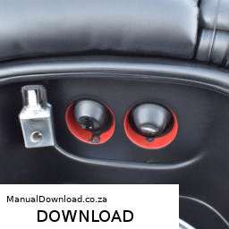
and amount of fluid as specified in your owner’s manual.
– **Check Fluid Level:** After filling, check the fluid level per the manufacturer’s instructions (typically involves running the engine and cycling through the gears).

#### 8. Reconnect the Battery
– **Reconnect Negative Terminal:** Once everything is reassembled, reconnect the negative battery terminal.

#### 9. Test Drive
– **Start the Engine:** Start the vehicle and let it idle for a few minutes.
– **Check for Leaks:** While the vehicle is running, check under the car for any signs of transmission fluid leaks.
– **Test Drive:** Take the car for a short test drive, paying attention to how it shifts. Ensure there are no warning lights on the dashboard related to transmission issues.

### Conclusion
Replacing the shift solenoid on a Mercedes-Benz SLK230 Kompressor or SLK320 requires careful attention to detail. Always refer to the vehicle’s service manual for specific torque specifications and any additional steps unique to your model year. If at any point you feel uncomfortable with the process, consult a professional mechanic.
The dipstick tube is a crucial component in an internal combustion engine, primarily used to measure the engine oil level. Typically made from metal or durable plastic, this tube serves as a conduit for the dipstick, a long, slender rod that is inserted into the tube for checking oil levels. The dipstick tube is usually located near the engine block, making it easily accessible for routine maintenance.

Functionally, the dipstick tube plays a vital role in ensuring the engine operates efficiently. The dipstick itself is marked with measurements that indicate the minimum and maximum oil levels, allowing vehicle owners or mechanics to quickly assess whether the engine has sufficient oil. regular checks are essential, as low oil levels can lead to inadequate lubrication, increasing friction and wear on engine components, potentially resulting in severe engine damage.

In addition to its primary function of oil level measurement, the dipstick tube can also serve as a guide for the dipstick to ensure it remains properly positioned. A well-maintained dipstick tube helps prevent oil leaks, which could occur if the tube becomes damaged or corroded. Overall, the dipstick tube is a small yet essential component that plays a significant role in engine maintenance and longevity, emphasizing the importance of regular oil checks in vehicle upkeep.

Download 2011 Mercedes-Benz C-Class C63 Owners Manual –

sale
Adjusting the gear selector cable on a Mercedes-Benz C-Class C63 is a precise task that requires attention to detail. click here for more details on the download manual…..


    Weistec supercharged W204 C63 fly by Weistec supercharged W204 Mercedes Benz C63 AMG M156 engine driven by IG: Peetsah63 Built by Mercedes service of …

    MERCEDES BENZ C63 AMG BUYERS GUIDE : DO NOT BUY Without watching this! A review of ALL the common problems with the Mercedes C63 AMG to make sure YOU buy the best car possible. Follow the …

Here’s a reverse order explanation of the process:

### Step 5: Test the Adjustment
– After securing all components, start the vehicle and test the gear selector. Shift through all gears to ensure smooth engagement and proper alignment. Check that the vehicle shifts correctly into each gear and that no warning lights appear on the dashboard.

### Step 4: Secure the Cable
– Once the adjustment is satisfactory, ensure all retaining clips and fasteners are securely in place to prevent the cable from moving out of position. Double-check that the cable is not pinched or obstructed by other components.

### Step 3: Fine-Tune the Adjustment
– With the cable loosely attached, fine-tune the adjustment by moving the cable slightly until you achieve the desired tension. This may involve pushing or pulling the cable gently while ensuring that the gear selector is in the correct position.

### Step 2: Initial Cable Attachment
– Attach the gear selector cable to the transmission and the gear selector lever, making sure the connection points are clean and free from debris. Ensure that the cable is seated properly in its mounting points.

### Step 1: Access the Gear Selector Cable
– Begin by safely raising the vehicle and securing it on Jack stands. Remove any necessary panels or covers to gain access to the gear selector cable. This may involve removing the center console or other components depending on the specific model.

### safety Precautions:
– Always wear safety gear, including gloves and safety glasses.
– Ensure the vehicle is on a flat surfacedownload Mercedes Benz C Class C63 workshop manual and secured to prevent movement.
– Disconnect the battery before starting to prevent electrical issues.

This reverse order approach should help you understand the steps involved in adjusting the gear selector cable for a Mercedes-Benz C-Class C63. Always refer to the vehicle’s service manual for specific details and torque specifications.
A pedal pad is an essential component of a vehicle that serves both functional and aesthetic purposes. Typically made from rubber or a composite material, pedal pads are designed to cover the surface of a car’s accelerator, brake, and clutch pedals. Their primary function is to provide traction and grip for the driver’s feet, ensuring that they can operate the pedals safely and effectively, especially in varying weather conditions. The textured surface of a pedal pad helps prevent slipping, which is crucial during sudden stops or when rapid acceleration is required.

In addition to their functional benefits, pedal pads also contribute to the overall look of the vehicle’s interior. They are available in various designs, colors, and materials, allowing drivers to customize their cars according to personal style preferences. Over time, pedal pads can wear out due to constant use, exposure to dirt, and the elements. As a result, they may need to be replaced periodically to maintain both safety and aesthetics.

Moreover, pedal pads can also help protect the underlying metal or plastic components of the pedals from wear and corrosion, extending their lifespan. In performance vehicles, specialized pedal pads designed for enhanced grip and responsiveness can significantly improve driving experience. Thus, pedal pads are a crucial aspect of automotive design that combines safety, functionality, and style.

Download 2011 Mercedes-Benz R-Class (W251) OEM Service & Repair Manual Software –

repair manual
Replacing the engine mount on a Mercedes Benz R Class W251 involves several steps. click here for more details on the download manual…..


    2007 Mercedes R350 Transmission RUNS AND DRIVES 251TYPE – mbiparts.com Used OEM Mercedes Part… … Buy parts for 2007 Mercedes R350! Call us at 1-916-638-6748 for a free quote! http://mbiparts.com 2007 Mercedes R350 …

    2007 Mercedes R350 Headlight / Head lamp RH GOOD SHAPE 251TYPE – mbiparts.com Used OEM Merced… … Buy parts for 2007 Mercedes R350! Call us at 1-916-638-6748 for a free quote! http://mbiparts.com 2007 Mercedes R350 …

Below is a reverse order of the process to provide you with a clear Understanding of how to complete the replacement.

### 8. reinstall Engine Covers and Components
– **Reattach any covers or components** that were removed during the process, such as the air intake or engine cover.
– **Reconnect any electrical connectors** that were unplugged.

### 7. Lower the Engine
– **Carefully lower the engine** back into position using the engine hoist or jack.
– **Align the engine mount** with the mounting bracket on the chassis.

### 6. Tighten Engine Mount Bolts
– **Securely tighten the engine mount bolts** to the manufacturer’s specified torque settings. Ensure that the mount is properly seated.

### 5. Install New Engine Mounts
– **Position the new engine mount** onto the bracket and align the holes.
– **Insert the mounting bolts** into the engine mount and hand-tighten them for now.

### 4. Remove the Old Engine Mount
– **Unscrew the bolts** securing the old engine mount to the engine and chassis.
– **Carefully slide out the old engine mount** from its position.

### 3. Prepare the Work Area
– **Disconnect the battery** to prevent any electrical shorts.
– **Lift the vehicle** using a jack and secure it with jack stands for safety.
– **Remove any necessary components** obstructing access to the engine mount, such as air intake parts or other ancillary components.

### 2. support the Engine
– **Use an engine hoist or jack** to support the weight of the engine before removing the mounts.
– Ensure that the engine is securely supported to prevent it from dropping.

### 1. Gather Tools and Parts
– **Collect necessary tools**: socket set, wrenches, torque wrench, engine hoist or jack, and safety equipment (gloves, goggles).
– **Acquire the correct replacement engine mounts** (OEM parts recommended).

### Note:
– Always consult the vehicle’s service manual for specific torque specificationsdownload Mercedes Benz R Class W251 OEM workshop manual and additional steps that may be necessary for your specific model.
– It’s crucial to follow safety precautions when working on vehicles, especially when lifting and supporting heavy components.

This reverse-order approach should help you visualize the overall process of replacing the engine mount on a Mercedes Benz R Class W251.
The horn relay is a crucial component in a vehicle’s electrical system, primarily responsible for controlling the operation of the car’s horn. It acts as an intermediary between the horn switch, typically located on the steering wheel, and the horn itself. When the driver presses the horn button, a low-current signal is sent from the switch to the relay. The relay is designed to handle a much larger current needed to activate the horn, which would be too much for the horn switch to manage directly.

The horn relay consists of an electromagnetic coil and a set of contacts. When the switch is activated, the coil energizes, creating a magnetic field that pulls the contacts together, allowing a high-current flow from the battery to the horn. This process not only protects the horn switch from high current but also ensures that the horn can operate efficiently and loudly when needed.

In addition to its primary function, the horn relay can also act as a safeguard against electrical faults. If there is a short circuit or an overload, the relay can help prevent damage to the vehicle’s wiring by breaking the circuit. This component is typically located in the fuse box or near the horn itself, and while it can last for years, it may occasionally need replacement if the horn fails to operate properly. Overall, the horn relay is an essential part of a vehicle’s safety and communication system, allowing drivers to signal their presence to others on the road.

Download 2013 Mercedes-Benz CLA250 (C117) 4MATIC OEM Download Service & Repair Manual Software –

australia
Replacing the upper control arm on a Mercedes-Benz CLA250 C117 4MATIC requires a good understanding of the vehicle’s suspension components and a careful approach to ensure safety and proper functionality. click here for more details on the download manual…..


    HIDDEN COMPARTMENTS AND CUPHOLDERS – Mercedes-Benz CLA Hidden compartments and cupholders locations are located through various places with in your vehicle. This particular video …

    🚗 🚕 2014 Mercedes-Benz CLA250 Tire Size 🔴 2014 Mercedes-Benz CLA250 Tire Size ______ Subscribe for More Rideshare Info Here: …

Here’s a detailed step-by-step guide to help you through the process, including descriptions of every component involved.

### Tools and Materials Needed:

1. **Tools:**
– Socket set (including 10mm, 13mm, 15mm, 17mm, and larger sockets)
– Wrench set (ratcheting preferred)
– Torque wrench
– Ball joint separator tool or pickle fork
– Rubber mallet
– Jack stands
– Floor jack
– Screwdrivers (flathead and Phillips)
– Pry bar
– Pliers
– Safety goggles and gloves

2. **Materials:**
– New upper control arm (OEM recommended)
– New rubber bushings (if not included with the control arm)
– New cotter pins (if applicable)
– Grease (if required for bushings)
– Loctite (thread locking compound, optional)

### Steps for Upper Control Arm Replacement:

#### 1. **Preparation:**
– Park the vehicle on a flat surface, engage the parking brake, and wear safety goggles and gloves.
– Gather all tools and parts needed for the replacement.

#### 2. **Lifting the Vehicle:**
– Use a floor jack to lift the front of the vehicle.
secure the vehicle with jack stands to ensure it is stable and safe to work under.

#### 3. **Remove the Wheel:**
– Using a lug wrench, loosen and remove the lug nuts on the front wheel where the control arm is being replaced.
– Remove the wheel and set it aside.

#### 4. **Accessing the Upper Control Arm:**
– Locate the upper control arm, which is mounted to the chassis and also connects to the steering knuckle.
– You will see the upper control arm has two mounting points: one at the chassis (typically a bolt) and another at the steering knuckle (a ball joint).

#### 5. **Removing the Upper Control Arm:**
– **Disconnect from Steering Knuckle:**
– Remove the cotter pin (if applicable) and the nut securing the ball joint to the steering knuckle using the appropriate socket.
– Use a ball joint separator tool or a pickle fork to separate the ball joint from the steering knuckle. Be cautious to avoid damaging the knuckle.

– **Remove Control Arm Bolts:**
– Locate and remove the bolts securing the upper control arm to the chassis. These may require a 10mm, 13mm, or larger socket.
– Support the control arm with one hand while removing the bolts to prevent it from falling.

#### 6. **Installing the New Upper Control Arm:**
– Position the new upper control arm in place, aligning it with the bolt holes on the chassis and the steering knuckle.
– Insert the bolts securing the upper control arm to the chassis and hand-tighten them initially.

– **Reconnect Ball Joint:**
– Align the ball joint with the steering knuckle and insert it.
secure it with the nut and tighten it to the manufacturer’s specifications using a torque wrench. Insert a new cotter pin if applicable.

#### 7. **Finalizing Installation:**
– Once all bolts are tightened, check that everything is secure.
– If the control arm has bushings, ensure they are properly seated and lubricated as necessary.

#### 8. **Reinstalling the Wheel:**
– Place the wheel back onto the hubdownload Mercedes Benz CLA250 C117 4MATIC OEM workshop manual and hand-tighten the lug nuts.
– Lower the vehicle from the jack stands and onto the ground.

#### 9. **Torque Wheel Lug Nuts:**
– Use a torque wrench to tighten the lug nuts to the manufacturer’s specified torque settings, ensuring they are properly secured.

#### 10. **Check Alignment:**
– After replacing suspension components like the upper control arm, it’s important to have the vehicle’s wheel alignment checked and adjusted if necessary. This ensures proper handling and tire wear.

### final Notes:
– Always refer to the specific service manual for your Mercedes-Benz CLA250 C117 4MATIC for exact torque specifications and any unique procedures that may be required.
– If you are unsure or uncomfortable with any step in this process, it may be best to consult a professional mechanic.
The High beam switch is a crucial component in a vehicle’s lighting system, responsible for controlling the operation of the High beam headlights. Positioned typically on the steering column or as a part of the headlight control system, this switch allows the driver to toggle between low and High beam settings. The primary function of High beams is to provide increased illumination for the road ahead, particularly in rural or poorly lit areas, enhancing visibility during nighttime driving.

When activated, High beams produce a more intense and focused beam of light, which can illuminate a greater distance compared to low beams. However, the use of High beams is regulated by traffic laws, as they can cause glare for oncoming drivers. The High beam switch usually allows for a momentary activation, enabling drivers to flash their High beams to signal to other road users, such as alerting oncoming traffic or indicating to a driver that they can proceed.

Modern vehicles may feature automatic High beam systems that utilize sensors to detect oncoming headlights or tail lights, automatically switching between High and low beams for optimal safety and convenience. Overall, the High beam switch plays a vital role in enhancing nighttime driving safety, allowing drivers to adapt their visibility to different driving conditions.

Download 2016 Mercedes-Benz C63 S AMG Coupe (C205) OEM Download Service & Repair Manual Software –

discount
Replacing the transmission fluid sensor on a Mercedes-Benz C63 S AMG Coupe (C205) involves several steps and requires specific tools and components. click here for more details on the download manual…..


    What goes wrong with a USED Mercedes-AMG C63 S? Have peace of mind when getting a used car. Buy a Vehicle History Check now! https://bit.ly/4b94XPc This week we do a deep …

    Mercedes 2014-2019 Tip Start Remote Starter (Non Keyless Go) Now Available! Our new remote starter for non Keyless Go: 2014-2015 ML 2016-2019 GLE 2014-2015 GL 2016-2019 GLS …

Below is a detailed guide on how to perform this replacement, including descriptions of the necessary tools and components.

### Tools and Equipment Needed:

1. **OBD-II Scanner**: To check for any fault codes before and after the replacement.
2. **Socket Set**: Metric sockets (10mm, 13mm, etc.) for removing bolts.
3. **Torque Wrench**: To ensure bolts are tightened to factory specifications.
4. **Screwdriver Set**: Flathead and Phillips for any clips or covers.
5. **Pliers**: For hose clamps or electrical connectors.
6. **Transmission Fluid**: OEM recommended fluid for your model.
7. **Oil Drain Pan**: To catch any fluid that spills during the process.
8. **Rags or Shop Towels**: For cleaning up any spills.
9. **Safety Glasses and Gloves**: To protect your eyes and hands during the procedure.

### Components Required:

1. **Transmission Fluid Sensor (OEM part)**: ensure you have the correct part specific to your C63 S AMG model.
2. **Transmission Fluid**: ensure you’re using the correct type recommended by Mercedes-Benz.
3. **Gasket or Sealing Ring**: If applicable, some sensors may require a new seal to prevent leaks.

### Replacement Procedure:

#### Step 1: Safety First
– **Disconnect the Battery**: Before starting, disconnect the negative terminal of the battery to avoid any electrical shorts or issues.

#### Step 2: Prepare the Vehicle
– **Lift the Vehicle**: Use a hydraulic jack to lift the front of the vehicle and secure it on jack stands. ensure it is stable before working underneath.
– **Drain Transmission Fluid**: Place an oil drain pan under the transmission pan. Remove the transmission pan drain plug (if equipped) or remove the pan to drain the fluid completely. Make sure you have enough containers to collect all the fluid.

#### Step 3: Locate the Transmission Fluid Sensor
– The transmission fluid sensor is typically located on the side of the transmission or near the transmission pan. Refer to your vehicle’s service manual for the exact location, as it may vary.

#### Step 4: Remove the Old Sensor
– **Disconnect Electrical Connector**: Locate the electrical connector for the sensor. Press the tab and gently pull it off to disconnect.
– **Remove mounting Bolts**: Using the appropriate socket, remove the bolts securing the sensor to the transmission. Be cautious as some fluid may still leak out.
– **Carefully Pull Out the Sensor**: Once the bolts are removed, gently pull the sensor out of its housing. You may need to wiggle it slightly to free it.

#### Step 5: Install the New Sensor
– **Prepare the New Sensor**: If your new sensor came with a new sealing ring or gasket, ensure that it is installed correctly.
– **Insert the New Sensor**: Align the new sensor with the mounting hole and insert it into place.
– **Secure with Bolts**: Replace the mounting bolts and tighten them to the manufacturer’s specifications using a torque wrench.

#### Step 6: Reconnect Electrical Connector
– **Reconnect the Sensor**: Push the electrical connector back onto the new sensor until you hear a click, indicating it is securely connected.

#### Step 7: Refill Transmission Fluid
– **Replace the Transmission Pan**: If you removed the pan, reinstall it with a new gasket (if needed)download Mercedes Benz C63 S AMG Coupe C205 OEM workshop manual and tighten the bolts to specification.
– **Refill Transmission Fluid**: Use the dipstick or fill port to add the new transmission fluid. Check the level according to the manufacturer’s specifications.

#### Step 8: Test the System
– **Reconnect the Battery**: Reattach the negative terminal of the battery.
– **Start the Engine**: Allow it to idle for a few minutes and then shift through all gears with your foot on the brake to circulate the fluid.
– **Check for Leaks**: Inspect the sensor area and the transmission pan for any leaks.
– **Use an OBD-II Scanner**: Check for any fault codes related to the transmission and clear them if necessary.

#### Step 9: Lower the Vehicle
– Once everything is checked and looks good, lower the vehicle carefully from the jack stands and remove the jack.

### Conclusion
Replacing the transmission fluid sensor on a Mercedes-Benz C63 S AMG Coupe involves careful attention to detail and adherence to safety protocols. It’s essential to use the right parts and tools, and ensure everything is reassembled correctly to avoid future issues. Always refer to the Mercedes-Benz service manual for specific details related to your vehicle model. If you’re unsure about any step, consider consulting with a professional mechanic.
The oil drain gasket, also known as the oil pan gasket or oil drain plug gasket, is a crucial component in an automobile’s lubrication system. It serves as a seal between the oil pan and the engine block, preventing oil leaks from occurring at the drain plug area. typically made from materials such as rubber, silicone, or cork, the oil drain gasket is designed to withstand high temperatures and the corrosive nature of engine oil.

When an engine operates, it generates a significant amount of heat, which can cause materials to expand and contract. The oil drain gasket must maintain a tight seal despite these changes to ensure that oil remains within the engine and does not leak onto the ground or into other engine components. A compromised gasket can lead to various issues, including reduced oil levels, which can result in engine wear or even catastrophic failure if not addressed promptly.

Regularly checking the condition of the oil drain gasket is essential, especially during oil changes. Signs of wear, such as cracks, tears, or hardening, indicate that it may need replacement. Additionally, improper installation can lead to leaks; therefore, it is crucial to ensure that the gasket is installed correctly and that the oil drain plug is tightened to the manufacturer’s specifications. Overall, the oil drain gasket plays a significant role in the overall health and efficiency of an engine.

Download 1998 Mercedes-Benz G-Class G300GD Kurz (W460/461) OEM Download Service & Repair Manual Software –

get
Replacing the spark plugs on a Mercedes-Benz G-Class G300GD Kurz W460/461 involves several steps. click here for more details on the download manual…..


    Umbau Teil 6 – W463 Bodykit auf W463A G63 AMG Look – Conversion Heute Teil 6 – Umbau W463 Bodykit auf W463A G63 Look Today part 6 – conversion W463 body kit to W463A G63 look …

    1991 Mercedes Benz 300GE 4×4 in the Canary Islands For more information visit www.CanaryIslandRover.com Classic 4×4 ready to take you to the ends of the Earth and back. 175k kms …

Below is a reverse order guide for the process:

### 9. Reconnect the Battery
– Reconnect the negative terminal of the battery to restore power to the vehicle.

### 8. Reassemble Engine Components
– If any engine covers or components were removed for access, reinstall them.
– Ensure all screws and bolts are tightened to the manufacturer’s specifications.

### 7. Install New Spark Plugs
– Thread the new spark plugs into the spark plug holes by hand to avoid cross-threading.
– Use a torque wrench to tighten the spark plugs to the specified torque (usually around 20 Nm, but check the manual for your model).

### 6. Connect Spark plug Wires or Coils
– Reattach the spark plug wires or coils to the new spark plugs.
– Ensure they are secured properly to prevent any misfiring.

### 5. Remove Old Spark Plugs
– Use a spark plug socket attached to a ratchet to carefully unscrew the old spark plugs.
– Inspect the old plugs for wear and signs of damage.

### 4. Prepare New Spark Plugs
– Check the gap on the new spark plugs with a gap gauge and adjust if necessary according to the manufacturer’s specifications.
– Apply a small amount of anti-seize compound to the threads of the new spark plugs (optional).

### 3. Gain access to Spark Plugs
– Depending on your engine configuration, you may need to remove components such as the engine cover, air intake, or other obstructions to access the spark plugs.

### 2. Gather tools and Materials
– You will need the following tools:
– Ratchet and socket set (specific size for spark plugs)
– Torque wrench
– Spark plug gap gauge
– Anti-seize compound (optional)
– Pliers (for wire removal if necessary)
– Obtain the correct OEM spark plugs for your G300GD.

### 1. Safety Precautions
– Ensure the engine is cool before starting the replacement.
– Disconnect the negative terminal of the battery to prevent any electrical issues.

By following these steps in reverse order, you can effectively replace the spark plugs on your Mercedes-Benz G-Class G300GD Kurz W460/461. Always refer to the vehicle’s service manual for specific instructionsdownload Mercedes Benz G Class G300GD Kurz W460 461 OEM workshop manual and torque specifications.
The fog light switch is a critical component in a vehicle’s lighting system, designed to control the operation of fog lights. Fog lights are specialized auxiliary lights that enhance visibility in adverse weather conditions, such as fog, rain, or snow, where standard headlights may struggle to illuminate the road effectively. The fog light switch is typically located on the vehicle’s dashboard, often integrated into the headlight control panel or as a standalone switch.

This component allows the driver to activate or deactivate the fog lights with ease. when engaged, fog lights produce a low, wide beam of light that is aimed at the road just in front of the vehicle, minimizing the amount of light that is reflected off moisture droplets in the air. This helps to reduce glare and improve visibility for the driver, allowing for safer navigation in challenging conditions.

The fog light switch may come in various designs, including a pull switch, toggle switch, or a button, depending on the make and model of the vehicle. Some modern vehicles feature advanced controls that allow for automatic fog light activation based on environmental conditions. Additionally, the switch often includes indicator lights to inform the driver when the fog lights are in use. Proper use of fog lights, as controlled by the switch, is essential for safe driving in low-visibility conditions, ensuring that the driver can see and be seen by others on the road.

Download 2015 Mercedes-Benz E-Class (S212) OEM Download Service & Repair Manual Software –

do your own repairs
Replacing the shock absorbers on a Mercedes-Benz E-Class S212 involves several steps and requires specific tools and components. click here for more details on the download manual…..


    Mercedes e350 front shock replacement with Bilstein struts STEP by STEP DIY for 2010-2016 E-Class… In this video Mike Icee will replace the front strut shocks and SPRINGS on a Mercedes W212 E350 e-class. These front bilstein …

    How to Replace Front Brakes 09-16 Mercedes-Benz E350 Buy Now! New Brake Pads from 1AAuto.com https://trq.video/ia-1ABPS02934 Brake pads wear out over time, much like tires, and …

Below is a detailed guide to help you through the process. Please ensure you have proper safety measures in place, including wearing safety glasses and gloves, and working on a flat surface.

### Components Required

1. **New Shock Absorbers**: OEM parts are recommended for compatibility.
2. **Mounting Hardware**: New bolts or nuts if the old ones show wear.
3. **Spring Compressors**: These tools are essential for safely compressing the coil springs.
4. **Tools**:
– Socket wrench set
– Torque wrench
– Pry bar
– Screwdrivers (flathead and Phillips)
– Pliers
– Hammer
– Jack and jack stands
– Wheel chocks

### Preparation Steps

1. **Gather Tools and Parts**: Ensure you have all the necessary tools and new shock absorbers ready.

2. **Safety First**: Park the vehicle on a level surface. Engage the parking brake and place wheel chocks behind the rear wheels.

3. **Loosen Lug Nuts**: If you are replacing front shock absorbers, loosen the lug nuts on the front wheels using a socket wrench, but do not remove them completely yet.

### Removal of Old Shock Absorbers

#### Front Shock Absorbers

1. **Lift the Vehicle**: Use a jack to lift the front of the vehicle, then secure it with jack stands. Remove the front wheels by fully removing the lug nuts.

2. **Access the Shock Absorber**: The shock absorber is located behind the wheel well. you may need to remove the wheel arch liner or other components obstructing access.

3. **Remove the Shock Absorber Bottom Bolt**: Locate the lower bolt securing the shock absorber to the control arm. Use a socket wrench to remove this bolt. you may need to hold the shock absorber in place with a pry bar if it rotates.

4. **Remove the Upper Mounting Nut**: open the hood to access the shock absorber’s upper mounting point. Remove the nut securing the shock to the strut tower using a socket wrench. There could be a plastic cover you need to remove first.

5. **Remove the Shock Absorber**: Gently pull the shock absorber down and out from the strut assembly.

6. **Use Spring Compressors**: If you are also replacing the coil spring, use spring compressors to safely compress the spring before removing it.

#### Rear Shock Absorbers

1. **Lift the Rear of the Vehicle**: Use the jack to lift the rear of the car and secure it with jack stands. Remove the rear wheels.

2. **Remove the Lower Shock Bolt**: Similar to the front, locate the lower bolt securing the shock to the rear axle and remove it.

3. **Remove the Upper Mounting Nut**: Access the upper mounting point, which may be accessible from the trunk or under the vehicle, and remove the nut.

4. **Remove the Shock Absorber**: Pull the shock absorber down and out of its mounting points.

### installation of New Shock Absorbers

#### For Front Shock Absorbers

1. **Install the New Shock Absorber**: Position the new shock absorber in place, aligning it with the upper mount and the lower control arm.

2. **Secure the Upper Mount**: Use the previously removed nut to secure the upper end of the shock absorber to the strut tower. Use a torque wrench to tighten it to the manufacturer’s specifications (consult the service manual for the correct torque value).

3. **Secure the Lower Mount**: Insert the lower boltdownload Mercedes Benz E Class S212 OEM workshop manual and tighten it to the specified torque.

4. **Reinstall Wheel Arch Liner**: If removed, reinstall the wheel arch liner.

#### For Rear Shock Absorbers

1. **Position the New Shock Absorber**: Insert the new shock absorber into the upper and lower mounts.

2. **Secure the Upper Mount**: Tighten the upper mounting nut using a torque wrench.

3. **Secure the Lower Mount**: Insert and tighten the lower bolt.

### Reassembly

1. **Reinstall the Wheels**: Place the wheels back on and hand-tighten the lug nuts.

2. **Lower the Vehicle**: Carefully remove the jack stands and lower the vehicle back to the ground using the jack.

3. **Tighten Lug Nuts**: Use a torque wrench to tighten the lug nuts to the specified torque.

4. **Final Checks**: Ensure everything is secure, and check for proper operation of the new shock absorbers by gently bouncing the vehicle.

5. **Test Drive**: Take the car for a test drive to ensure that the new shock absorbers are functioning correctly.

### Conclusion

Replacing the shock absorbers on a Mercedes-Benz E-Class S212 can enhance ride comfort and handling. Always consult the vehicle’s service manual for specific torque specifications and procedures. If you are unsure about any steps, consider seeking professional assistance.
A rearview camera is an advanced safety feature commonly integrated into modern vehicles, designed to enhance visibility and assist drivers when reversing. Positioned at the rear of the vehicle, typically near the license plate, this camera captures a wide-angle view of the area directly behind the car. The images captured by the camera are transmitted to a display screen located on the dashboard or rearview mirror, providing real-time video feed to the driver.

The primary purpose of a rearview camera is to help prevent accidents and improve safety, particularly in urban environments where obstacles like pedestrians, children, and other vehicles may be difficult to see. Many rearview camera systems also include additional features such as grid lines, which help drivers gauge distances and angles when maneuvering in tight spaces. Some advanced systems even utilize sensors that can detect objects behind the vehicle and provide audio or visual alerts to warn the driver of potential hazards.

In addition to enhancing safety, rearview cameras are often part of a larger suite of driver assistance technologies, contributing to the overall functionality of systems such as parking aids and collision avoidance systems. As regulations in many regions mandate the installation of rearview cameras in new vehicles, they have become an essential component for improving roadway safety and reducing the likelihood of accidents during reversing maneuvers.