Download 2003 Mercedes-Benz C-Class C200 Kompressor T-Modell (W203) OEM Download Service & Repair Manual Software –

book store
Repairing the shift interlock on a Mercedes Benz C-Class C200 Kompressor T Modell W203 can be a bit technical, but I’ll break it down into simple steps. click here for more details on the download manual…..


    Mercedes Benz W203 Secret Function

    Mercedes C63 AMG BURNOUT & BLOWS engine. YouTube hashtags and shorts YES GBL SQUAD! Don’t forget to subscribe and follow my other social media accounts!

The shift interlock is a safety feature that prevents you from shifting out of “Park” unless the brake pedal is pressed. If it’s not working correctly, you might have trouble shifting gears. Here’s how to approach the repair:

### Tools and materials Needed:
– Screwdrivers (Phillips and flathead)
– Socket set or wrenches
– Replacement parts (if needed)
– Safety gloves
– Flashlight (for better visibility)

### Step-by-Step Guide:

1. **Safety First**:
– Ensure the car is parked on a level surface and the engine is off.
– Engage the parking brake.
– Disconnect the car battery (remove the negative terminal) to prevent any electrical issues.

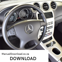
2. **Locate the Shift Interlock Mechanism**:
– The shift interlock mechanism is usually located around the gear shifter. You may need to remove the shifter cover to access it.
– Use a flathead screwdriver to gently pry up any trim pieces around the shifter. Be careful not to damage them.

3. **Remove the Gear Shifter Assembly**:
depending on the model, you might need to remove screws or bolts holding the shifter assembly in place. Use the appropriate socket or screwdriver to do this.
– Once screws are removed, lift the shifter assembly carefully out of the console.

4. **Inspect the Interlock Mechanism**:
– Look for any visible signs of damage or wear in the interlock mechanism. Sometimes, dirt or debris can cause it to malfunction.
– Check the wiring connections to make sure there are no loose or damaged wires.

5. **Cleaning**:
– If you find any dirt or debris, use a clean cloth to wipe the mechanism. You can use a small brush to reach tight spots.
– Make sure the area around the interlock is clean and free of obstructions.

6. **Testing the Mechanism**:
– Before reassembling everything, you can manually test the interlock mechanism. Press the brake pedal and see if you can shift out of “Park.” If it works, the issue may have been dirt or a loose connection.

7. **Reassemble the Gear Shifter**:
– If everything looks good and works well, carefully place the shifter assembly back into position.
– Replace and tighten any screws or bolts you removed earlier.

8. **Reinstall the Trim**:
– Snap or screw the trim pieces back into place around the shifter.

9. **Reconnect the Battery**:
– Reconnect the negative terminal of the battery.

10. **Test the Shifter**:
– Start the cardownload Mercedes Benz C Class C200 Kompressor T Modell W203 OEM workshop manual 
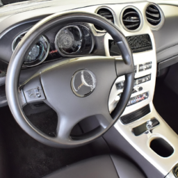
and test the shifter again. Make sure you can shift smoothly from “Park” to “Drive” or “Reverse” when the brake pedal is pressed.

### Additional Tips:
– If cleaning and inspecting don’t resolve the issue, you may need to replace the shift interlock solenoid or the entire shifter assembly. Consult your vehicle’s manual for specific part numbers and procedures.
– If you’re unsure at any step, it’s always best to consult a professional mechanic.

By following these steps, you should be able to address the shift interlock issue in your Mercedes Benz C-Class. Good luck with your repair!
An alarm system in a car is a sophisticated security device designed to deter theft and protect the vehicle and its contents. It typically consists of a series of sensors, an audible alarm, and a control unit that monitors the car for unauthorized access or suspicious activity. The primary function of an alarm system is to detect potential threats, such as attempted break-ins or tampering with the vehicle.

Most modern car alarm systems feature a combination of different sensors, including door sensors, motion detectors, and impact sensors. Door sensors are triggered when a door is opened without the proper key or remote, while motion detectors can sense movement within the cabin. Impact sensors respond to vibrations or shocks, such as someone attempting to break a window or tamper with the car’s exterior.

When the alarm system is triggered, it emits a loud siren or beep, alerting the owner and potentially scaring off thieves. Many systems also integrate with remote keyless entry, allowing the owner to arm or disarm the alarm from a distance. Some advanced alarm systems include GPS tracking, enabling owners to locate their vehicle in the event of theft.

Furthermore, modern car alarm systems can be connected to a smartphone app, providing real-time notifications and control over the alarm status. Overall, a car alarm system is an essential component of automotive security, enhancing the protection of both the vehicle and its occupants.

Download 2005 Mercedes-Benz SLK-Class (R171) OEM Download Service & Repair Manual Software –

book shop
Certainly! click here for more details on the download manual…..


    HIAUTO Wheel Bearings Inner diameter 45mm Wheel Bearings Kit Premium Quality guarantee of functio… HIAUTO Wheel …

    Buying a used Mercedes SLK R171 – 2004-2011, Review with Common Issues https://differentcarreview.com/ Buying a used Mercedes-Benz SLK R171 – produced from 2004 to 2011 What is the best engine, …

Here’s a detailed guide on how to replace the shock mounts on a Mercedes Benz SLK Class R171 OEM, outlined with bullet points for clarity:

### Tools and Materials Needed

– **Jack and Jack Stands**
– A hydraulic jack to lift the vehicle safely.
– Jack stands to secure the vehicle in place.

– **Lug Wrench**
– A tool for loosening and tightening the lug nuts on the wheels.

– **Socket Set**
– A set of sockets (both metric and standard) and a ratchet to remove bolts. Common sizes may include 10mm, 13mm, and 17mm.

– **Torque Wrench**
– To ensure bolts are tightened to the manufacturer’s specifications.

– **Pry Bar**
– Useful for providing leverage to remove stubborn components.

– **Spring Compressors**
– Essential for safely compressing the coil spring to prevent injury while removing the strut assembly.

– **Penetrating Oil**
– To lubricate rusted or stuck bolts for easier removal.

– **Replacement Shock Mounts**
– OEM parts are recommended for proper fit and performance.

### Procedure

– **Preparation**
– Park the vehicle on a level surface and engage the parking brake.
– Gather all tools and materials needed for the job.

– **Lifting the Vehicle**
– Use the lug wrench to loosen the lug nuts on the front wheels (do Not remove them completely).
– Position the hydraulic jack under the vehicle’s designated lift points and raise it high enough to place jack stands securely.

– **Removing the Wheels**
– Once the vehicle is securely raised, remove the lug nuts completely and take off the front wheels.

– **Accessing the Strut Assembly**
– Locate the strut assembly, which is connected to the lower control arm and the upper strut mount.
– Spray penetrating oil on the bolts connected to the strut mount for easier removal.

– **Removing the Strut Assembly**
– Using the appropriate socket, remove the bolts that secure the strut to the steering knuckle (lower connection).
– Remove any additional components (like sway bar links) that may obstruct access to the strut assembly.
– If necessary, use a pry bar to gently separate the strut from the steering knuckle.

– **Compressing the Coil Spring**
install spring compressors onto the coil spring of the strut assembly.
– Gradually tighten the compressors evenly to compress the spring enough to relieve pressure on the strut mount.

– **Removing the Old Shock Mount**
– Once the spring is compressed, remove the top nut securing the strut mount to the strut (this may be a large nut requiring a socket).
– Take off the old shock mount and inspect for wear or damage.

– **Installing the New Shock Mount**
– Place the new OEM shock mount onto the strut.
– Reattach the top nutdownload Mercedes Benz SLK Class R171 OEM workshop manual and tighten it to the manufacturer’s specifications using a torque wrench.

– **Reassembling the Strut Assembly**
– Carefully release the tension on the spring compressors, allowing the coil spring to seat onto the new mount securely.
– Reinstall the strut assembly back into the vehicle by reversing the removal steps.

– **Reattaching Components**
– Reattach any components you removed, such as sway bar links and bolts connecting the strut to the steering knuckle.
– Ensure all bolts are tightened to the appropriate torque specifications.

– **Reinstalling the Wheels**
– Place the wheels back onto the hub and hand-tighten the lug nuts.
– Lower the vehicle off the jack stands using the hydraulic jack.

– **Final Checks**
– Once the vehicle is back on the ground, use the lug wrench to tighten the lug nuts in a star pattern to ensure even seating.
– Perform a final inspection of the strut assembly and surrounding components to ensure everything is securely in place.

– **Test Drive**
– Take the vehicle for a short test drive to ensure proper handling and that there are no unusual noises.

### Conclusion
– Regularly check the shock mounts and suspension components for wear and tear to maintain a smooth driving experience. Following this procedure will help ensure a successful shock mount replacement on your Mercedes Benz SLK Class R171.
The valve cover bolt is a crucial component in an internal combustion engine, specifically designed to secure the valve cover to the engine cylinder head. The valve cover, also known as the rocker cover, serves as a protective shield for the engine’s valvetrain components, including the camshaft, rocker arms, and valves. The primary function of the valve cover is to prevent dirt, debris, and contaminants from entering the engine, while also containing oil that lubricates these moving parts.

Valve cover bolts are typically made of high-strength materials, such as steel or aluminum, to withstand the engine’s harsh operating conditions, including temperature fluctuations and vibrations. They often feature a hexagonal or socket head design, which allows for easy installation and removal with standard tools. The bolts are usually accompanied by washers or gaskets to ensure a tight seal, preventing oil leaks that could lead to engine damage or performance issues.

Over time, valve cover bolts can become corroded or stripped, especially if they are frequently removed for maintenance or repairs. In such cases, it is essential to replace them to maintain the integrity of the valve cover and ensure the engine operates efficiently. Proper torque specifications are critical when installing valve cover bolts, as overtightening can cause warping of the valve cover or damage to the engine components.

Download 1992 Mercedes-Benz S-Class Coupe (C126) OEM Download Service & Repair Manual Software –

book store
Checking the wheel alignment on a Mercedes-Benz S-Class Coupe (C126) can be a bit technical, but I’ll break it down into simple steps for you. click here for more details on the download manual…..


    Mercedes Benz W126 SEC 560 / V8 / OZ MITO 2

    Mercedes Automatic Window Reset – Restore Functionality! After disconnecting the battery in a Mercedes, you may lose the auto up comfort feature for your windows. In this video, we show …

Wheel alignment refers to how the wheels are positioned on the vehicle. Proper alignment ensures that your car drives straight, handles correctly, and wears tires evenly.

### What You’ll Need:
– A flat, level surface (like a garage floor)
– A measuring tape
– A spirit level (optional, but helpful)
– A piece of string or a ruler

### Steps to Check Wheel Alignment:

1. **Park on a Level Surface:**
– Make sure your car is parked on a flat, level surface. This is important for an accurate measurement.

2. **Check Tire Pressure:**
– Ensure all tires are properly inflated to the manufacturer’s recommended pressure. You can find this information on a sticker inside the driver’s door or in the owner’s manual.

3. **Inspect Tires:**
look for any uneven wear on the tires. If one side is more worn than the other, it could indicate alignment issues.

4. **Measure the Front and Rear Wheel Distances:**
– Use your measuring tape to measure the distance between the front tires at the front (from the outer edges of the tires) and then again at the rear (from the outer edges of the tires).
– Note down both measurements. Ideally, the distance at the front should be slightly less than at the rear. This is called “toe-in.”

5. **Check for Toe-In:**
– If the front measurement is larger than the rear measurement, your wheels may be “toe-out,” which is generally not ideal. If the front is smaller, then you have “toe-in,” which is usually what you want.

6. **Check for Camber:**
– Camber refers to the angle of the wheels when viewed from the front. You can visually inspect this by looking at the top of the tires. If the top of the tire leans inwards, you have negative camber; if it leans outwards, that’s positive camber.
– A small spirit level can be used to check the vertical alignment of the wheels.

7. **Check for Caster:**
– Caster is the angle of the steering axis when viewed from the side. This is a bit harder to check without special tools, but you can look for any signs that the steering feels off-center or the car pulls to one side.

8. **Test Drive:**
– Take the car for a short test drive. Pay attention to how the car download Mercedes Benz S Class Coupe C126 OEM workshop manualhandles. If it pulls to one side, drifts, or feels unstable, it may need professional adjustment.

### Conclusion:
If you notice any significant misalignment in measurements or during your test drive, it’s best to have a professional mechanic check the alignment. Adjusting wheel alignment requires special equipment and expertise, especially on a luxury car like the Mercedes-Benz S-Class. Regular checks can help extend the life of your tires and improve your driving experience!
The transmission dipstick is a vital component in an automobile’s transmission system, primarily found in automatic vehicles. It serves a crucial role in monitoring the transmission fluid level and quality, which are essential for the smooth operation of the transmission. Typically, the dipstick is a long, slender tube with a handle that extends into the transmission housing. At the end of the dipstick, there is a flat or pointed end that can be inserted into the transmission to gauge fluid levels.

Checking the transmission fluid level with the dipstick is a straightforward process. The vehicle should be parked on a level surface, and the engine usually needs to be running or at operating temperature to get an accurate reading. By pulling out the dipstick and wiping it clean, the operator can then reinsert it to see where the fluid level falls on the marked scale—often indicating “Full,” “Add,” or “Low.”

In addition to measuring fluid levels, the dipstick also allows users to assess the condition of the transmission fluid. Healthy fluid is typically bright red and clear, while dark, brownish, or burnt-smelling fluid may indicate a problem, such as overheating or contamination. Regularly checking the transmission fluid using the dipstick can help prevent transmission failure, ensuring the vehicle operates efficiently and prolonging its lifespan.

Download 1977-1981 MERCEDEZ BENZ W123 Service Repair Manual –

service manual
Exhaust manifold repair on a Mercedes-Benz W123 requires careful attention to detail and the right tools. click here for more details on the download manual…..


    Mercedes-Benz W123 upgrade

    W123 300DT Cheap Fix #2: Automatic Transmission Shift Problems Cost $0 Jerking Shifts are very annoying. Don’t let anyone sell you a new transmission. It might be something simple. Link to resources to …

Here’s a detailed breakdown of the process, including the necessary tools and steps:

– **Tools and Equipment Needed:**
– **Socket Set**: A comprehensive metric socket set (8mm to 17mm) for removing bolts and nuts.
– **Torque Wrench**: To ensure proper torque settings when reassembling.
– **Ratchet and Extensions**: For reaching difficult bolts, especially in tight spaces.
– **Pliers**: Needle-nose and regular pliers for handling small components and hoses.
– **Flathead and Phillips Screwdrivers**: For removing any screws or clips.
– **Wrench Set**: Open-end and box-end wrenches for various fasteners.
– **Scraper or Wire Brush**: For cleaning surfaces of the manifold and cylinder head.
– **Gasket Scraper or Razor Blade**: To remove old gasket material from surfaces without damaging them.
– **New Exhaust Manifold Gasket**: Ensure you have an OEM replacement gasket for a proper seal.
– **High-Temperature RTV Silicone (optional)**: For additional sealing if needed.
– **Safety Gear**: Gloves, goggles, and a dust mask to protect against debris and fumes.

– **Preparation:**
– **Disconnect the Battery**: Always disconnect the negative terminal to prevent electrical shorts.
– **Raise the Vehicle**: Use jack stands to safely elevate the car for better access to the exhaust components.
– **Remove Engine Cover**: If applicable, take off the Engine cover to access the exhaust manifold.

– **Removing the Exhaust Manifold:**
– **Disconnect Exhaust System**: Loosen and detach the exhaust pipe from the manifold. This may require cutting or unbolting the connection.
– **Remove Heat Shields**: If present, take off any heat shields that protect the manifold.
– **Detach Air Intake Components**: Remove any air intake tubing or components obstructing access to the manifold.
– **Unbolt the Manifold**: Using the socket set, carefully remove all bolts securing the manifold to the cylinder head. Keep track of the order and location of each bolt.
– **Lift off the Manifold**: Once all bolts are removed, carefully lift the manifold off the engine. Be cautious of any remaining connections or sensors.

– **Inspecting the Exhaust Manifold:**
– **Check for Cracks or Damage**: Inspect the manifold for any signs of cracks, warping, or damage. If damaged, consider replacing the manifold.
– **Clean Surfaces**: Use a scraper or Wire brush to clean the mating surfaces on both the manifold and the engine. Remove all old gasket material to ensure a proper seal.

– **Installing the New Gasket:**
– **Position the New Gasket**: Place the new exhaust manifold gasket onto the cylinder head, ensuring it aligns properly with the bolt holes and exhaust ports.

– **Reinstalling the Exhaust Manifold:**
– **Position the Manifold**: Carefully place the exhaust manifold back onto the cylinder head, ensuring the gasket stays in place.
– **Hand-Tighten Bolts**: Start by hand-tightening the bolts to hold the manifold in position; do not fully tighten yet.
– **Torque to Specification**: Use a torque wrench to tighten the bolts in a crisscross pattern to the manufacturer’s specified torque settings. This ensures even pressure on the gasket.

– **Reconnecting Components:**
– **Reattach Exhaust System**: Securely reconnect the exhaust pipe to the manifolddownload MERCEDEZ BENZ W123 workshop manual and tighten the bolts.
– **Reconnect Air Intake Components**: reinstall any air intake components or tubing that were removed earlier.
– **Reattach Heat Shields**: If applicable, reinstall any heat shields removed during disassembly.

– **Final Checks:**
– **Inspect for Loose Connections**: Double-check all connections, ensuring everything is securely fastened.
– **Reconnect the Battery**: Reconnect the negative battery terminal.
– **Start the Engine**: Start the Engine and listen for any leaks or unusual sounds. Look for any exhaust leaks around the manifold.

– **Post-Repair Inspection:**
– **Check for Exhaust Leaks**: After a short drive, recheck for any exhaust leaks or loose connections.
– **Monitor Engine Performance**: Keep an eye on the engine’s performance, ensuring it runs smoothly without any check Engine lights.

By following these steps and using the appropriate tools, you should be able to successfully repair the exhaust manifold on a Mercedes-Benz W123. Always refer to specific vehicle service manuals for any unique procedures or specifications related to your model.
A boost controller is an essential component in turbocharged and supercharged engines, designed to regulate the amount of air pressure, or boost, delivered to the engine’s intake. The primary function of the boost controller is to optimize Engine performance by managing the turbocharger’s or supercharger’s output, ensuring that the Engine operates efficiently and safely under varying conditions.

There are two main types of boost controllers: manual and electronic. Manual boost controllers typically consist of adjustable valves that allow the driver to set the desired boost level manually. These controllers are often simpler and less expensive but can require more hands-on adjustments and monitoring. On the other hand, electronic boost controllers utilize advanced sensors and microprocessors to automatically adjust the boost pressure based on real-time Engine parameters, such as RPM, throttle position, and intake air temperature. This allows for more precise control and often results in improved performance and reliability.

Boost controllers play a crucial role in preventing Engine knock, which can occur when the air-fuel mixture ignites prematurely due to excessive pressure. By managing boost levels, these devices help maintain the engine’s longevity while maximizing power output. Enthusiasts and tuners often use boost controllers to fine-tune their vehicles for specific performance goals, whether for daily driving or competitive racing. Overall, a well-tuned boost controller can significantly enhance a vehicle’s performance and driving experience.

Download 2010 Mercedes-Benz ML-Class (W164) OEM Download Service & Repair Manual Software –

owners manual
Replacing the tie rod end on a Mercedes Benz ML Class W164 involves several steps and requires specific tools. click here for more details on the download manual…..


    How to Change Language on Mercedes Dash W164 ML350 X164 GL350 and others W164 ML350 Language Change How-to using the confusing steering wheel buttons.

    MERCEDES W164 ML350 550 320 63 AMG 4MATIC REAR DIFFERENTIAL OIL FLUID HOW TO SERVICE CHANGE REPLA… TORQUE SPECS ON PLUGS IS 30NM. REPLACE THESE EVERY 40000 MILES OR YOU WILL END UP DESTROYING THE …

Below are detailed descriptions of the tools and steps you need to follow for a successful replacement.

### Tools Required:

– **Jack and Jack Stands**
– A hydraulic floor jack to lift the vehicle and jack stands to secure it safely.

– **Lug Wrench**
– Used to remove the wheel nuts. Make sure it fits the size of the wheel lugs.

– **Socket Set**
– A metric socket set (usually 10mm to 21mm) for removing bolts and nuts associated with the tie rod end.

– **Wrench Set**
– A set of metric wrenches for loosening and tightening various bolts.

– **Tie Rod End Puller Tool**
– A specialized tool that helps separate the tie rod end from the steering knuckle without damaging the components.

– **Torque Wrench**
– To ensure that the bolts are tightened to the manufacturer’s specifications.

– **Pry Bar**
– To help leverage parts apart if they are stuck.

– **Grease Gun with Grease**
– To lubricate the new tie rod end, if it has a grease fitting.

– **Safety Goggles and Gloves**
– For personal protection during the replacement process.

### Step-by-Step Procedure:

– **Preparation**
– Park the vehicle on a flat, level surface. Ensure the parking brake is engaged to prevent any movement during the procedure.

– **Lift the Vehicle**
– Use the jack to lift the front of the vehicle and secure it with jack stands. Always double-check that the vehicle is stable before working underneath.

– **Remove the Wheel**
– Use the lug wrench to remove the wheel on the side where the tie rod end will be replaced. This will provide better access to the suspension components.

– **Locate the Tie Rod End**
– Identify the tie rod end, which connects the steering rack to the steering knuckle. It typically looks like a ball joint at the end of a rod.

– **Remove the Cotter Pin**
– If applicable, remove the cotter pin that secures the castle nut on the tie rod end using pliers.

– **Loosen the Castle Nut**
– Use the appropriate socket or wrench to loosen and remove the castle nut holding the tie rod end to the steering knuckle.

– **Separate the Tie Rod End**
– Use the tie rod end puller tool to carefully separate the tie rod end from the steering knuckle. Place the puller tool around the tie rod end and apply pressure to push it out without damaging the surrounding components.

– **Remove the Tie Rod End from the Steering Rack**
– If necessary, loosen the lock nut on the inner tie rod end using a wrench. Then, twist the tie rod end to unscrew it from the steering rack.

– **Install the New Tie Rod End**
– Screw the new tie rod end into the steering rack, ensuring it is threaded properly. Tighten the lock nut to secure it in place.

– **Reattach the Tie Rod End to the Steering Knuckle**
position the new tie rod end into the steering knuckledownload Mercedes Benz ML Class W164 OEM workshop manual and replace the castle nut. Tighten it securely and insert a new cotter pin if necessary.

– **Reattach the Wheel**
– Place the wheel back onto the hub and hand-tighten the lug nuts. Lower the vehicle back to the ground.

– **Torque the Lug Nuts**
– Use a torque wrench to tighten the lug nuts to the manufacturer’s specifications.

– **Check Alignment**
– After replacing the tie rod end, it’s advisable to have the vehicle’s alignment checked to ensure that the steering is accurate and to avoid uneven tire wear.

– **Test Drive**
– Take the vehicle for a short test drive to ensure everything is functioning correctly and there are no unusual noises or handling issues.

### final Notes:

– Always consult the vehicle’s service manual for specific torque specifications and additional guidance.
– If you are unsure about any part of this process, consider seeking help from a professional mechanic.
The wheel cylinder is a crucial component of a vehicle’s drum brake system, playing a vital role in the overall braking performance and safety. Typically found in vehicles with drum brakes, the wheel cylinder is a hydraulic component that converts hydraulic pressure from the brake master cylinder into mechanical force to actuate the brake shoes.

When the driver presses the brake pedal, hydraulic fluid is pushed from the master cylinder into the wheel cylinder. This fluid enters the cylinder through an inlet port and exerts pressure on the pistons housed within the cylinder. As the pistons move outward, they push the brake shoes against the inner surface of the brake drum. This contact creates friction, which slows down or stops the rotation of the wheel, effectively bringing the vehicle to a halt.

Wheel cylinders typically consist of a cylindrical housing that contains one or two pistons, along with rubber seals to prevent fluid leakage. Over time, due to exposure to heat, moisture, and other environmental factors, the seals can deteriorate, leading to fluid leaks and reduced braking efficiency. This can result in uneven braking or complete brake failure, making regular inspections and timely replacements essential for vehicle safety.

In summary, the wheel cylinder is a pivotal component in the drum brake system, responsible for translating hydraulic action into mechanical force to apply the brakes effectively, thereby ensuring safe vehicle operation.

Download 2006 Mercedes-Benz R-Class R350 (W251) OEM Download Service & Repair Manual Software –

service
Replacing the shock mounts on a Mercedes-Benz R-Class R350 (W251) involves several steps and requires specific tools and components. click here for more details on the download manual…..


    2007 Mercedes R350 Headlight / Head lamp RH GOOD SHAPE 251TYPE – mbiparts.com Used OEM Merced… … Buy parts for 2007 Mercedes R350! Call us at 1-916-638-6748 for a free quote! http://mbiparts.com 2007 Mercedes R350 …

    2007 Mercedes R350 Engine / Motor RUNS AND DRIVES 251TYPE – mbiparts.com Used OEM Mercedes P… … Buy parts for 2007 Mercedes R350! Call us at 1-916-638-6748 for a free quote! http://mbiparts.com 2007 Mercedes R350 Engine …

Below is a detailed guide to performing this task.

### Tools and Materials Required

1. **Tools:**
– Socket set (metric)
– Wrenches (metric)
– Torque wrench
– Floor jack
– Jack stands
– Suspension spring compressor (if necessary)
– Impact wrench (optional but recommended)
screwdrivers (flat and Phillips)
– Pliers
– Hammer
– Rubber mallet
– Safety goggles and gloves

2. **Materials:**
– New shock mounts (OEM or aftermarket)
– New shock absorbers (if replacing)
– New hardware (if necessary)
– Grease (optional, for mounting surfaces)

### Components of the Shock Mount

– **Shock Absorber:** The part that dampens the impact of the road and controls the rebound of the suspension.
– **Shock Mount (Upper):** The component that connects the shock absorber to the vehicle’s body, often including a rubber bushing to absorb vibrations.
– **Nut/Bolt Assembly:** Fasteners that secure the shock mount to the body and the shock absorber.
– **Dust Boot:** A protective cover that prevents dirt and debris from entering the shock absorber.
– **Spring Seat:** sometimes integrated with the shock mount, it holds the coil spring in place.

### Steps for Shock Mount Replacement

1. **Safety First:**
– Ensure the vehicle is on a flat surface.
– Wear safety goggles and gloves.

2. **Lift the Vehicle:**
– Use a floor jack to lift the vehicle at the designated lifting points.
– Secure the vehicle with jack stands to ensure stability.

3. **Remove the Wheel:**
– Use a socket wrench to remove the lug nuts and take off the wheel. This will give you access to the shock assembly.

4. **Inspect Shock Absorbers:**
– Check for any signs of leakage or damage. If the shock absorbers are worn, consider replacing them at this time.

5. **Remove Shock Absorber:**
– Locate the bolts securing the shock absorber at the bottom (usually at the lower control arm) and the top (attached to the body).
– Use an impact wrench or socket wrench to remove these bolts. It may require holding the shock shaft with a wrench to prevent it from spinning.
– Carefully pull the shock absorber out from the bottom.

6. **Remove Old Shock Mount:**
– At the top of the shock absorber, the shock mount is typically secured with a nut. Use the appropriate socket to remove this nut.
– Once the nut is removed, separate the shock mount from the shock absorber. You may need to tap it gently with a hammer or use a rubber mallet If it’s stuck.

7. **Install New Shock Mount:**
– Take the new shock mount and position it onto the top of the new or existing shock absorber.
– Secure it with the nut, making sure it’s tight but do not overtighten at this stage.

8. **Reinstall Shock Absorber:**
– Insert the shock absorber back into its mounting position. Line up the bottom of the shock with the control arm and secure it with the bolts.
– Torque the bolts to the manufacturer’s specifications (check the repair manual for specifics).

9. **Reattach the Wheel:**
– Place the wheel back ondownload Mercedes Benz R Class R350 W251 OEM workshop manual and hand-tighten the lug nuts.
– Lower the vehicle back to the ground using the floor jack and then fully tighten the lug nuts in a criss-cross pattern.

10. **Test the Installation:**
– Before driving, press down on the vehicle to ensure the suspension compresses and rebounds appropriately.
– Check for any unusual noises or movements.

11. **Repeat for Other Side (if necessary):**
If you are replacing the shock mounts on both sides, repeat the above steps for the other side.

### Important Tips

– Always refer to the vehicle’s service manual for specific torque specifications and detailed diagrams.
If the vehicle has a self-leveling suspension, ensure you understand the system before proceeding with the replacement.
– Consider replacing the shock absorbers If you notice any signs of wear or If the vehicle has high mileage.

### Conclusion

Replacing the shock mounts on a Mercedes-Benz R-Class R350 (W251) can significantly improve ride quality and handling. Always take the necessary precautions and, If unsure, consult a professional mechanic to perform the replacement for you.
The steering box, also known as the steering gear, is a crucial component of a vehicle’s steering system. It is responsible for translating the rotational motion of the steering wheel into the lateral movement of the vehicle’s wheels. Essentially, it serves as the intermediary that allows the driver to control the direction of the vehicle effectively.

There are several types of steering boxes, including recirculating ball, rack and pinion, and worm gear systems. Each type has its own mechanism for achieving this motion, but they all share the common purpose of enabling precise steering control. The recirculating ball steering box uses a series of ball bearings to reduce friction and improve steering feel, making it common in older vehicles and trucks. On the other hand, the rack and pinion system, which has become more prevalent in modern vehicles, utilizes a gear mechanism that translates the rotary motion of the steering wheel into the linear motion needed to turn the wheels.

The steering box is typically mounted to the vehicle’s chassis and is connected to the steering column, which transmits the driver’s input. It also connects to the tie rods that link to the wheels, allowing for direct control over the vehicle’s direction. Proper functioning of the steering box is essential for safe driving, as any wear or malfunction can lead to poor steering response, reduced handling, and even loss of control of the vehicle. Regular maintenance and inspection are vital to ensure its longevity and reliability, contributing significantly to overall driving safety and comfort.

Download 2017 Mercedes-Benz E-Class E220d T-Modell (S213) All-Terrain OEM Download Service & Repair Manual Software –

repair
Replacing the struts on a Mercedes Benz E-Class E220d T Modell S213 All Terrain can seem daunting, especially if you have little mechanical experience. click here for more details on the download manual…..


    Start of production of the new Mercedes-Benz E-Class 2024 in plant Sindelfingen Start of production of the new 2024 Mercedes-Benz E-Class in plant Sindelfingen #E200, #E300, #E400, #E300e, #E400d Salon …

    Mercedes E 220 d All Terrain – Off-Road Drive 2017 Mercedes-Benz E 220 d All Terrain – Off-Road Drive. Color: Designo Hyacinth Red Metallic. Whether on rough tracks, …

However, I’ll break down the process into simple steps to help you understand what’s involved. Please remember that working on your vehicle can be dangerous, and if you’re not comfortable doing it yourself, it’s always best to consult a professional mechanic.

### Tools and Materials Needed:
– New struts (OEM recommended)
– Jack and jack stands
lug wrench
– Socket set
– Wrench set
– Torque wrench
– Screwdriver
– Spring compressor (if necessary)
– Safety goggles and gloves

### Step-by-Step Guide:

#### 1. **Preparation:**
– **Safety First:** Wear safety goggles and gloves to protect yourself.
– **Gather Tools:** Make sure you have all your tools and new struts ready.

#### 2. **Lift the Vehicle:**
– **Park on a Level Surface:** Ensure the car is parked on a flat, stable surface.
– **Loosen lug Nuts:** Before lifting the vehicle, use the lug wrench to slightly loosen the lug nuts on the wheel where you’ll be replacing the strut.
– **Jack Up the Vehicle:** Use a jack to lift the front or rear of the vehicle, depending on which strut you’re replacing. Make sure to place the jack stands securely under the frame to support the car.
– **Remove the Wheel:** Once the car is securely lifted and supported, remove the lug nuts completely and take off the wheel.

#### 3. **Remove the Old Strut:**
– **Locate the Strut:** The strut is typically located behind the wheel assembly. You may need to remove some components (like the brake line or sway bar link) to access it.
– **Unbolt the Strut:** Using the socket and wrench, remove the bolts that hold the strut to the steering knuckle and any bolts at the top of the strut (usually under the hood).
– **Carefully Remove the Strut:** Once all bolts are removed, carefully slide the strut out of its housing. If it’s stuck, gently wiggle it free.

#### 4. **Install the New Strut:**
– **Position the New Strut:** Place the new strut in the same position as the old one. It should slide into the housing easily.
– **Secure the Strut:** Reattach the bolts to the steering knuckle and tighten them securely. Then, tighten the bolts at the top of the strut.
– **Reattach Components:** If you removed any components (like brake lines or sway bar links), reattach them now.

#### 5. **Reinstall the Wheel:**
– **Put the Wheel Back On:** Place the wheel back onto the hub and hand-tighten the lug nuts.
– **Lower the Vehicle:** Carefully remove the jack stands and lower the vehicle back to the ground.

#### 6. **Tighten lug Nuts:**
– **Final Tightening:** Once the vehicle is on the ground, use the torque wrench to tighten the lug nuts to the manufacturer’s specifications. This ensures they are securely fastened.

#### 7. **Repeat as Necessary:**
– If you’re replacing multiple struts, repeat the above steps for each strut.

#### 8. **Test Drive:**
– **Check Your Work:** Once everything is back together, take the car for a short test drive to ensure everything feels right. Pay attention to any unusual noises or download Mercedes Benz E Class E220d T Modell S213 All Terrain OEM workshop manualhandling issues.

### Important Tips:
– **Consult Your Manual:** Always refer to your vehicle’s service manual for specific details and torque specifications.
– **Take Your Time:** Don’t rush through the process. If you Feel uncertain at any point, it’s wise to seek help from a professional.
– **Safety First:** Always ensure the vehicle is securely supported before working under it.

By following these steps, you should have a clearer understanding of how to replace the struts on your Mercedes Benz E-Class E220d T Modell S213 All Terrain. good luck, and stay safe!
The seat cushion is a fundamental component of automotive seating systems, playing a vital role in both comfort and safety for vehicle occupants. Positioned at the base of the seat, it serves as the primary support for the driver and passengers, influencing the overall driving experience. Typically made from various materials such as foam, gel, or air, the seat cushion is designed to absorb shock and provide a comfortable seating surface that contours to the body shape, distributing weight evenly.

One of the key functions of the seat cushion is to enhance comfort during long drives by reducing pressure points, which can lead to fatigue and discomfort. Manufacturers often employ advanced foam technologies, such as memory foam or high-resilience foam, to improve the cushioning effect and ensure longevity. Additionally, some premium vehicles feature heated or cooled seat cushions, enhancing passenger comfort in different weather conditions.

From a safety perspective, the seat cushion also plays a role in crash protection. It is engineered to work in conjunction with the seat frame and restraint systems, helping to keep occupants securely in place during an impact. Furthermore, in modern vehicles, seat cushions may integrate additional features like lumbar support and adjustable settings, allowing for personalized comfort and improved ergonomics. Overall, the seat cushion is a critical element that combines functionality, safety, and comfort, making it indispensable in the design of automotive interiors.

Download 2008 Mercedes-Benz CLK-Class CLK350 Cabrio (A209) OEM Download Service & Repair Manual Software –

discount
Replacing the clutch release bearing in a Mercedes-Benz CLK350 Cabrio (A209) involves several steps and components. click here for more details on the download manual…..


    Crucial Maintenance & upgrade: Mercedes CLK500 W209 First Must do Maintenance & upgrade: CLK500 W209 Sports Brake Package. 5 projects in 2 hours. Rotors, pads, Bleeding and …

    Avoid These Costly Problems – Mercedes CLK – C and E-Class… Avoid These Costly Problems – Mercedes CLK – C-class and E-class…If you have decided to buy a Mercedes CLK, C-class or an …

This is a detailed guide to help you understand the process, but please note that working on your vehicle can be complex, and if you’re not confident in your mechanical skills, it’s best to consult a professional mechanic.

### Required Tools and Equipment
1. **Basic Hand Tools**:
– Ratchet and socket set (including extensions)
– Wrenches (metric sizes)
– Screwdrivers (flat and Phillips)
– Pliers
2. **Special Tools**:
– Clutch alignment tool (specific to the clutch kit)
– Torque wrench
3. **Lifting Equipment**:
– Car jack and jack stands or a hydraulic lift
4. **Brake cleaner**: To clean any components during the process
5. **New Clutch Release Bearing**: Ensure it’s OEM or a quality aftermarket part
6. **New Clutch Kit (optional but recommended)**: includes the clutch disc, pressure plate, and release bearing
7. **Gasket Maker/Sealant**: If needed for reassembly

### Safety Precautions
– Always work in a well-ventilated area.
– Wear safety goggles and gloves.
– Ensure the vehicle is securely lifted and supported before working underneath it.

### Step-by-Step Guide

#### 1. Preparation
– **Disconnect the Battery**: Start by disconnecting the negative terminal of the battery to ensure safety.
– **Lift the Vehicle**: Use a car jack to lift the front of the vehicle and secure it on jack stands.

#### 2. Remove the Transmission
1. **Remove the Driveshaft**: Depending on whether your vehicle has a manual or automatic transmission, you may need to remove the driveshaft. This usually involves removing bolts at the differential and sliding the driveshaft out.
2. **Disconnect Transmission Linkages**: Remove any linkages or cables connected to the transmission.
3. **Unbolt the Transmission**: Locate the transmission mounting bolts and remove them. These may be located on both the Engine side and the transmission cross-member.
4. **Support the Transmission**: Use a transmission jack to support the weight of the transmission.
5. **Remove the Transmission**: Carefully slide the transmission out of the Engine bay. Be cautious of any wires or hoses that may be attached.

#### 3. Access the Clutch Assembly
1. **Remove the Clutch Fork**: The clutch fork is usually held in place by a retaining clip or bolt. Remove it to gain access to the release bearing.
2. **Remove the Pressure Plate and Clutch Disc**: Unbolt the pressure plate from the flywheel. There are usually several bolts that need to be removed in a crisscross pattern to relieve tension evenly. Once unbolted, the pressure plate can be removed, followed by the clutch disc.

#### 4. Replace the Clutch Release Bearing
1. **Remove the Old Bearing**: The release bearing is typically mounted on the clutch fork. Slide it off and inspect for any wear or damage.
2. **Install the New Bearing**: Place the new release bearing onto the clutch fork, ensuring it is seated properly.

#### 5. Reassemble the Clutch Assembly
1. **Install the Clutch Disc**: Position the new clutch disc onto the flywheel. Make sure it is aligned properly. You can use a clutch alignment tool to help with this.
2. **Install the Pressure Plate**: Place the pressure plate over the clutch discdownload Mercedes Benz CLK Class CLK350 Cabrio A209 OEM workshop manual and bolt it back to the flywheel in a crisscross pattern to ensure even clamping force. Refer to your service manual for the specific torque specifications.
3. **Reinstall the Clutch Fork**: Attach the clutch fork back to its original position.

#### 6. Reinstall the Transmission
1. **Position the Transmission**: Carefully slide the transmission back into place, ensuring it aligns with the Engine and input shaft.
2. **Reattach Transmission Linkages**: Reconnect any linkages or cables that were disconnected.
3. **Secure the Transmission**: Bolt the transmission back into place securely.
4. **Reinstall the Driveshaft**: If you removed the driveshaft, reinstall it by sliding it back into place and securing it with bolts.

#### 7. Final Steps
1. **Reconnect the Battery**: Once everything is reassembled, reconnect the negative terminal of the battery.
2. **Test the Clutch**: Before taking the car for a drive, test the clutch operation by pressing the pedal and ensuring it feels normal.
3. **Check for Leaks**: After starting the vehicle, check for any fluid leaks underneath.

### Conclusion
Replacing the clutch release bearing on a Mercedes-Benz CLK350 Cabrio is a labor-intensive process that requires a good understanding of vehicle mechanics. Always consult the service manual specific to your vehicle for torque specifications and additional details. If you’re unsure at any point, it’s wise to seek the help of a professional mechanic to avoid any potential damage to your vehicle.
A strut mount is a crucial component of a vehicle’s suspension system, serving as a connection point between the vehicle’s body and its strut assembly. The strut itself is an integral part of the suspension system, providing support, stability, and handling characteristics while absorbing shocks from road imperfections. The strut mount plays a vital role in this system by anchoring the strut to the vehicle’s chassis, ensuring that the strut can effectively manage the forces generated during driving.

Typically located at the top of the strut, the strut mount is designed to accommodate vertical and lateral loads, allowing for smooth movement of the strut during compression and rebound. It often features a rubber or polyurethane bushing that acts as a damping material, helping to isolate vibrations and noise from the road, which contributes to a more comfortable ride for passengers. Additionally, the strut mount may include a bearing that allows for the rotation of the strut during steering, enhancing the vehicle’s maneuverability.

Over time, strut mounts can wear out due to exposure to road conditions, corrosion, and the stresses of driving. Symptoms of a failing strut mount include clunking noises, uneven tire wear, and poor handling. Regular inspection and timely replacement of strut mounts are essential for maintaining the overall performance and safety of the vehicle’s suspension system.

Download 2008 Mercedes-Benz S-Class S420 (W221) OEM Download Service & Repair Manual Software –

books
Replacing the gearbox synchronizer in a Mercedes-Benz S-Class S420 W221 is a complex procedure that typically requires mechanical experience, specialized tools, and a good understanding of automotive systems. click here for more details on the download manual…..


    Check Coolant Level on Mercedes #mercedes #cclass #eclass #sclass #ml #shorts #viral #fyp #coola…

    Fix your Mercedes ABC – don’t do coilovers. Premium Mercedes S and SL models have the most advanced factory suspension ever offered called ABC (Active Body Control).

However, I can break it down into simpler terms for better understanding. Please note that if you’re not comfortable with such procedures, it’s always best to consult a professional mechanic. Here’s a simplified guide on what the process generally involves:

### Tools and Materials Needed:
1. **Basic hand Tools**: Wrenches, sockets, screwdrivers, etc.
2. **Gearbox Oil**: To refill the gearbox after replacement.
3. **Replacement Synchronizer**: Make sure it’s the correct part for the S420 W221.
4. **Torque Wrench**: For properly tightening bolts.
5. **Shop Manual**: For specific torque settings and step-by-step guidance.

### Steps to Replace the Gearbox Synchronizer:

1. **Safety First**:
– Ensure the car is parked on a flat surface.
– Disconnect the battery to prevent any electrical issues.
– Use wheel chocks to prevent the vehicle from rolling.

2. **Remove the Transmission**:
– **Lift the Vehicle**: Use a jack to lift the car and secure it on jack stands.
– **Remove the Driveshaft**: Locate the driveshaft connected to the gearbox and unbolt it.
– **Disconnect Linkages**: Unclip and disconnect any shift linkages or electrical connectors attached to the transmission.
– **Unbolt the Transmission**: Remove the bolts securing the transmission to the engine. you may need to support the transmission with a jack.

3. **Access the Gearbox**:
– Once the transmission is removed, place it on a sturdy work surface. Make sure you have good lighting.
– **Remove the transmission Case**: Unbolt the case to gain access to the internal components.

4. **Locate the Synchronizer**:
– Inside the gearbox, you’ll find the gears and synchronizers. The synchronizer is usually located between the gearset and the input shaft.
– Carefully take note of how the parts are arranged as you will need to reassemble them in the same order.

5. **Replace the Synchronizer**:
– Remove the old synchronizer by carefully prying it out. Be gentle to avoid damaging other components.
– Clean the area where the new synchronizer will be installed.
– Install the new synchronizer by pressing it into place. Make sure it fits snugly and is aligned properly.

6. **Reassemble the Gearbox**:
– Once the new synchronizer is in place, reattach the transmission case.
– Ensure all internal components are correctly positioned and that there are no leftover parts.

7. **Reinstall the Transmission**:
– Lift the transmission back into placedownload Mercedes Benz S Class S420 W221 OEM workshop manual and secure it with bolts.
– Reconnect the driveshaft and any linkages or electrical connectors that were previously disconnected.

8. **Refill Gearbox Oil**:
– Locate the fill plug on the transmission and refill it with the appropriate gearbox oil. Consult your shop manual for the correct type and amount.

9. **Reconnect the Battery**:
– Once everything is reassembled, reconnect the battery.

10. **Test Drive**:
– Start the engine and take the car for a test drive. Pay attention to the shifting; it should be smooth without any grinding or unusual noises.

### Final Notes:
– This is a high-level overview, and you may encounter specific challenges depending on the condition of your vehicle.
– Make sure to follow any specific torque settings and procedures outlined in the service manual for your S-Class.
– If at any point you feel unsure, it’s best to consult with or hire a professional mechanic to ensure the job is done safely and correctly.

Remember, working on a vehicle can be dangerous if not done properly, so always prioritize safety.
A vacuum pump is a vital component in many automotive systems, particularly in vehicles equipped with internal combustion engines. Its primary function is to create a vacuum, or negative pressure, which is essential for various operations within the vehicle. One of the most common applications of a vacuum pump is in the brake booster system. In this context, the vacuum pump generates a vacuum that assists in amplifying the force applied to the brake pedal, making it easier for the driver to engage the brakes effectively. This is especially important in vehicles with turbocharged engines, which may not generate sufficient manifold vacuum at low engine speeds.

In addition to brake assist, vacuum pumps can also be used for other functions, such as operating the HVAC system’s controls, engaging certain engine components, and managing emissions systems. They can be driven mechanically via the engine or can be electric, providing flexibility in design and integration. The efficiency and reliability of a vacuum pump are crucial for maintaining optimal vehicle performance and safety. Over time, vacuum pumps can wear out or develop leaks, leading to a drop in performance or functional failures. Regular maintenance and checks can help ensure that the vacuum pump operates effectively, contributing to the overall efficiency and safety of the vehicle.

Download 1985 Mercedes 190D Service Repair Manual 85 –

books
The Check Engine Light (CEL) on a 1985 Mercedes 190D can be a signal of various issues within the vehicle’s engine or emissions system. click here for more details on the download manual…..


    mercedes 190d problem

    190e m111 kompressor engine swap wiring w201 190e kompressor swaped m111 Instagram tag komprezor190.

To understand why the light is on and how to diagnose the problem, follow these steps, which include detailed descriptions of the components involved.

### tools and Equipment Needed:
1. **OBD-I Scanner**: Since the 1985 190D uses an early On-Board Diagnostics system (OBD-I), it’s essential to have a compatible scanner or a multimeter for some tests.
2. **Basic Hand Tools**: Wrenches, screwdrivers, pliers, etc., for inspecting and replacing components.
3. **Repair Manual**: A service manual specific to the 190D for reference on specifications and procedures.

### Step-by-Step Diagnosis

1. **Visual Inspection**:
– **Dashboard Indicator**: The Check Engine Light should be illuminated on the dashboard. This is usually located on the left side of the dashboard panel.
– **Wiring and Connectors**: Inspect the wiring harness and connectors under the hood for signs of wear, fraying, or corrosion. Ensure all connections are secure.

2. **Retrieve Diagnostic Codes**:
– **Location of Diagnostic Port**: The diagnostic port on the 190D is usually found under the dashboard near the driver’s seat. Look for a rectangular connector.
– **Connecting the Scanner**: connect your OBD-I scanner to the diagnostic port. Turn the ignition key to the “on” position without starting the engine.
– **Reading Codes**: Follow the scanner instructions to retrieve any stored trouble codes. Write down these codes for further investigation.

3. **Check Engine Components**:
– **Fuel System**:
– Inspect the fuel filter and fuel lines for clogs or leaks.
– Examine the fuel injectors for proper operation. A clogged injector can lead to poor engine performance, triggering the CEL.
– **Air Intake System**:
– Inspect the air filter. If it is clogged, replace it as restricted airflow can cause performance issues.
– Check the intake hoses for cracks or leaks that may allow unmetered air into the engine.
– **Exhaust System**:
– Examine the catalytic converter. A failing or clogged catalytic converter can trigger the CEL.
– Look for exhaust leaks, which can affect emissions readings.
– **Ignition System**:
– Check the condition of the spark plugs and wires. Worn or damaged spark plugs can lead to misfires and trigger the CEL.
– Inspect the ignition coil for proper function.
– **Sensors**:
– **Mass Air Flow (MAF) Sensor**: Located in the air intake path, it measures the amount of air entering the engine.
– **Throttle Position Sensor (TPS)**: Mounted on the throttle body, it monitors the position of the throttle plate.
– **Oxygen Sensors**: Located in the exhaust system, they monitor the level of oxygen in the exhaust gases.

4. **Perform Tests**:
– **Multimeter Checks**: Use a multimeter to check for proper voltagedownload Mercedes 190D 85 workshop manual and resistance in critical components like the MAF, TPS, and oxygen sensors.
– **Vacuum Leaks**: perform a vacuum leak test using a smoke machine or by spraying carburetor cleaner around the intake manifold and vacuum lines while the engine is running.

5. **Clear Codes and Test Drive**:
– If you have resolved the issue or replaced faulty components, use the OBD-I scanner to clear the trouble codes.
– Take the vehicle for a test drive to see if the Check Engine Light reappears. Monitor the performance and listen for unusual sounds.

6. **Professional Help**:
– If you cannot diagnose or resolve the issue on your own, consider taking the vehicle to a certified Mercedes-Benz mechanic who has the proper diagnostic tools and expertise.

### Conclusion

By following these steps, you can systematically diagnose and address the reason behind the Check Engine Light on your 1985 Mercedes 190D. Regular maintenance and inspections can help prevent issues and keep your vehicle running smoothly. Always refer to the vehicle’s service manual for specific details regarding components and systems.
The intake manifold gasket is a critical component in an internal combustion engine, serving as the seal between the intake manifold and the engine block or cylinder head. Its primary function is to prevent air and fuel mixture from leaking out of the intake system, ensuring that the engine receives the correct air-fuel ratio for optimal performance. Typically made from rubber, silicone, or composite materials, the gasket is designed to withstand high temperatures and pressures within the engine.

The intake manifold is responsible for directing the air-fuel mixture from the throttle body to the individual cylinders. A properly functioning intake manifold gasket is essential for maintaining engine efficiency and performance. If the gasket deteriorates or fails, it can lead to several problems, including vacuum leaks, which can cause rough idling, decreased fuel efficiency, and increased emissions. Symptoms of a faulty intake manifold gasket may also include engine misfires, poor acceleration, and a noticeable drop in power.

Replacement of the intake manifold gasket usually requires disassembling parts of the engine, making it a labor-intensive process. Regular maintenance and inspections can help identify potential issues before they escalate, ensuring the longevity and reliability of the engine. Overall, the intake manifold gasket plays a vital role in the overall performance and efficiency of an engine, making it an essential component for vehicle operation.