Download DATSUN PICKUP 250 Series Service Repair Manual –

workshop
Replacing the planetary gear in the gearbox of a Datsun Pickup 250 can seem daunting, but with careful steps and some basic tools, you can tackle this project. click here for more details on the download manual…..


    SYMPTOMS OF A BAD ECM (ENGINE CONTROL MODULE) In this video, you will learn 4 symptoms of a bad or failing engine control module. Watching this video will help you diagnose to …

    1992 Nissan Datsun Pickup AX For Sale | Northeast Auto Imports 1992 Nissan Datsun Pickup AX For Sale | Northeast Auto Imports 1992 Nissan Datsun Pickup AX review …

Here’s a straightforward guide to help you through the process:

### Tools and materials Needed:
– Socket set and wrenches
– Screwdrivers (flathead and Phillips)
– Pliers
– Torque wrench
– Replacement planetary gear set
– Gasket sealant or new gasket (if needed)
– Oil for the gearbox (check your vehicle’s manual for specifications)
– Clean rags
– Drain pan

### Safety Precautions:
1. **Work in a well-ventilated area** to avoid inhaling fumes.
2. **Wear safety glasses and gloves** to protect yourself.
3. **Ensure the vehicle is securely lifted** on jack stands if you’re working underneath it.

### Step-by-Step Guide:

#### 1. **Preparation:**
– **Disconnect the Battery:** Start by disconnecting the negative terminal of the battery to prevent any electrical issues.
– **Gather Your Tools:** Have all your tools and replacement parts ready.

#### 2. **Drain the Gearbox Oil:**
– Place a drain pan under the gearbox.
– Remove the drain plug (usually at the bottom of the gearbox) and let the oil completely drain out.

#### 3. **Remove the Gearbox:**
– **Disconnect the Gear Shifter:** Depending on the design, you may need to remove the gear shifter or linkage to access the gearbox.
– **Unbolt the Gearbox:** Locate the bolts holding the gearbox to the engine and remove them. There may also be bolts securing it to the frame or crossmember.
– **Support the Gearbox:** Use a jack to support the gearbox as you remove it.
– Carefully slide the gearbox out from the vehicle.

#### 4. **Disassemble the Gearbox:**
– **Remove the Cover:** Use the appropriate screwdriver or socket to remove the bolts holding the gearbox cover. Be cautious as there may be springs or components under pressure.
– **Take Note of Assembly:** As you remove parts, take pictures or notes to Remember how everything fits together.
– **Remove the Planetary Gear Set:** Locate the planetary gear set within the gearbox. Carefully remove it, noting how it is positioned.

#### 5. **Install the New Planetary Gear Set:**
– Place the new planetary gear set into the gearbox in the same position as the old one.
– Make sure it rotates freely and is seated properly.

#### 6. **Reassemble the Gearbox:**
– Reattach the gearbox cover, ensuring any gaskets are in good condition or replaced.
– Tighten the bolts securely but be careful not to overtighten, as this could damage the cover.

#### 7. **Reinstall the Gearbox:**
– Carefully lift the gearbox back into position under the vehicle.
– Reattach any bolts, ensuring everything is aligned properly and secured.
– Reconnect the gear shifter or linkage as necessary.

#### 8. **Refill Gearbox Oil:**
– Replace the drain plug and refill the gearbox with the appropriate oil. Check your vehicle’s manual for the correct typedownload DATSUN PICKUP 250 workshop manual and amount.

#### 9. **Reconnect the Battery:**
– Reconnect the negative terminal of the battery.

#### 10. **Test Drive:**
– Start the vehicle and let it idle for a few minutes. Check for any leaks around the gearbox.
– Take the vehicle for a short test drive to ensure everything is functioning properly.

### Final Tips:
– **Take Your Time:** Don’t rush through the process. Ensure each step is done correctly.
– **Consult a Manual:** If you have access to a service manual for your Datsun Pickup 250, it can provide specific torque specifications and additional details about your gearbox.
– **Ask for Help:** If you feel unsure at any stage, consider asking a friend with more mechanical experience for assistance.

By following these steps, you should be able to replace the planetary gear in your Datsun Pickup 250’s gearbox with confidence!
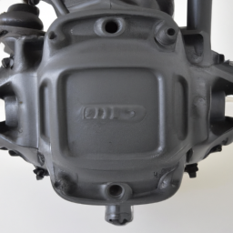
The dipstick tube is a crucial component of an internal combustion engine’s lubrication system, serving as a guide for the dipstick, which is used to check the engine oil level. Typically constructed from metal or durable plastic, the dipstick tube is a vertical or angled tube that extends from the oil pan to the engine’s top. Its primary function is to provide a pathway for the dipstick to slide in and out, allowing for easy access to the oil reservoir.

The dipstick itself is marked with graduated measurements, indicating the oil level within the engine. When the engine is off and allowed to settle, the dipstick is removed from the tube, wiped clean, and then reinserted to obtain an accurate reading of the oil level. Proper oil levels are essential for maintaining engine health, as insufficient oil can lead to inadequate lubrication, increased friction, overheating, and potential engine damage.

In addition to facilitating oil level readings, the dipstick tube can also play a role in the overall design and efficiency of the engine. Its placement and design can affect oil circulation and ensure that the dipstick remains securely in place during operation. Furthermore, some dipstick tubes are designed to minimize the risk of oil leaks, ensuring that the engine remains clean and free of contaminants. Regular checks using the dipstick and tube are vital for vehicle maintenance, promoting longevity and performance.

Download 2001 Mercedes-Benz C-Class C200 Kompressor T-Modell (W203) OEM Download Service & Repair Manual Software –

book shop
Replacing the blower motor on a Mercedes-Benz C-Class C200 Kompressor T Modell W203 can be a detailed process. click here for more details on the download manual…..


    MERCEDES-BENZ C 300 – ADDING COOLANT – WHERE TO How to add coolant in a Mercedes-Benz C 300 is essential for your mechanic to know. Do not add coolant to your own car instead …

    How to change front wheel bearing on MERCEDES-BENZ W203 C-Class [TUTORIAL AUTODOC] How to change front wheel bearing / hub bearing / wheel bearing kit on MERCEDES-BENZ C240 2 (W203) 2.6 Saloon …

Below are the steps outlined in reverse order to help you understand the procedure clearly.

### 8. Reassemble the Dashboard and Components
– **Reconnect Battery**: Reconnect the negative terminal of the battery.
– **Reattach Dashboard**: If you removed any parts of the dashboard, reattach them, ensuring all screws and clips are securely fastened.
– **Replace Trim Panels**: Reinstall any trim panels or covers that were removed during the process.

### 7. Final Checks
– **Test the Blower Motor**: Before reassembling everything, turn on the vehicle and check that the blower motor operates correctly at all speed settings.
– **Check for Leaks**: Look for any signs of air leaks or unusual noises that may indicate improper installation.

### 6. Reinstall the New Blower Motor
– **Position the New Motor**: Insert the new blower motor into the housing, ensuring it is seated properly.
– **Secure with Screws**: Using the screws you removed earlier, securely attach the blower motor to the housing.

### 5. Disconnect the Old Blower Motor
– **Unplug Electrical Connector**: Carefully disconnect the electrical connector from the old blower motor.
– **Remove the Old Motor**: Unscrew and remove the old blower motor from its housing.

### 4. Access the Blower Motor
– **Remove the Glove Compartment**: Open the glove compartment and remove any screws or clips to take it out, giving you access to the blower motor housing.
– **Remove Any Obstructing Panels**: Depending on the model, you may need to take off other panels or components to reach the blower motor.

### 3. Prepare the work Area
– **Gather Tools and Parts**: Collect necessary tools such as screwdrivers, wrenches, and the new blower motor.
– **Disconnect Battery**: Always start by disconnecting the negative terminal of the battery to avoid electrical issues.

### 2. Safety Precautions
– **Wear Safety Gear**: Use gloves and safety glasses to protect yourself during the replacement process.
– **Ensure a Safe Environment**: work in a well-ventilated area, preferably on a flat surface.

### 1. Gather Information
– **Get the Right Replacement Part**: Ensure you have the correct OEM blower motor for the W203 model. It’s important to check compatibility before beginning the replacement.

By following these steps in reverse order, you can effectively undersdownload Mercedes Benz C Class C200 Kompressor T Modell W203 OEM workshop manualtand the process of replacing the blower motor in a Mercedes-Benz C-Class C200 Kompressor T Modell W203. Always consult the vehicle’s service manual for specific details and torque specifications.
A shift boot is an essential component found in vehicles equipped with manual or automatic transmissions. It serves several important purposes, both functional and aesthetic. Primarily, the shift boot is a protective cover that surrounds the gear shifter or gear lever. Its primary function is to conceal the internal mechanisms of the transmission, preventing dirt, dust, and debris from entering the shifting assembly. This protection helps to ensure smooth operation and longevity of the transmission components.

Typically made from flexible materials such as leather, vinyl, or rubber, the shift boot can come in various styles and designs to complement the interior of the vehicle. The material choice often reflects the overall design and luxury level of the car, with higher-end models featuring leather boots that enhance the tactile experience of shifting gears.

In addition to its protective role, the shift boot contributes to the overall aesthetic of the vehicle’s interior. It can come in different colors, patterns, and stitching styles, allowing for customization and personalization. A well-designed shift boot can enhance the look of the center console and contribute to a cohesive design within the cockpit.

Furthermore, the shift boot often incorporates a ring or trim piece that secures it to the base of the shift lever, ensuring that it stays in place during operation. In some vehicles, it may also include a mechanism to dampen vibrations, providing a more comfortable driving experience. Overall, the shift boot is a small yet significant component that plays a vital role in both functionality and style within a vehicle’s interior.

Download 2013 Hyundai i40 (VF) OEM Download Service & Repair Manual Software –

online
Performing a wheel alignment check on a Hyundai i40 VF OEM involves a series of steps and the use of specific tools. click here for more details on the download manual…..


    Replacing Radiator Cap – Bad Cap Signs & Symptoms & How Radiator Caps Really Work When should I replace my radiator cap? What does the radiator cap really do anyway? These are common questions technicians …

    Dont make this mistake when you grease you caliper sliding pins | typical mechanic TIP Due to factors beyond the control of RB The Mechanic, it cannot guarantee against unauthorized modifications of this information.

Below are the detailed descriptions of the tools needed and the procedure for checking wheel alignment:

### Tools Required

– **Wheel Alignment Machine**:
– A specialized machine that uses lasers or cameras to measure the angles of the wheels relative to the vehicle’s centerline and each other. It provides precise data on camber, caster, and toe angles.

– **Digital Camber Gauge**:
– A handheld device used to measure the camber angle of each wheel. It can be attached to the wheel rim to provide accurate readings.

– **Toe Plates**:
– Flat metal plates that are placed against the front tires to measure the toe angles. They help in determining the difference between the front and rear measurement of the wheels.

– **Tape Measure or Ruler**:
– A standard measuring tool to check the distance between the front and rear edges of the front tires, which helps in calculating the toe angle.

– **Wheel Chocks**:
– Devices used to prevent the vehicle from rolling when it is lifted or stationary during the alignment check.

– **Jack and Jack Stands**:
– A hydraulic or mechanical jack to raise the vehicle safely, along with jack stands to support it securely while you work.

– **Tire Pressure Gauge**:
– A tool to check the tire pressure, which should be at the manufacturer’s recommended level before starting the alignment check.

– **Alignment Specifications**:
– Reference data that contains the specific alignment angles recommended by Hyundai for the i40 VF model. This can usually be found in the vehicle’s service manual.

### Procedure

– **Preparation**:
– Park the vehicle on a flat, level surface to ensure accurate measurements.
– Ensure that the tires are properly inflated to the recommended pressure.
– Check the suspension components for wear or damage, as this can affect alignment.

– **Initial Measurements**:
– Use the digital camber gauge to measure the camber angle of each wheel. Record the readings for comparison with OEM specifications.
– Check toe angles using toe plates. Place the plates against the front tires and measure the distance between the front and rear edges of the tires.

– **Use the Wheel Alignment Machine**:
– Drive the vehicle onto the alignment machine according to the manufacturer’s instructions. Ensure it is centered and the wheels are straight.
– Follow the machine’s calibration process to ensure it is set up correctly.
– Take the readings from the machine, which will display camber, caster, and toe angles.

– **Compare to Specifications**:
– Compare all measurements (camber, caster, toe) to Hyundai’s OEM specifications for the i40 VF.
– Identify any discrepancies in angle measurements.

– **Adjustments**:
– If any angles are out of specification, adjust the tie rods for toe alignment, and use camber bolts or adjusters for camberdownload Hyundai i40 VF OEM workshop manual and caster adjustments as needed.
– Follow the vehicle’s service manual for the proper adjustment procedures.

– **Final Checks**:
– Once adjustments are made, recheck the alignment using the wheel alignment machine to ensure that all angles are now within specifications.
– Conduct a final verification with the digital camber gauge and toe plates to confirm accuracy.

– **Test Drive**:
– After completing the alignment, take the vehicle for a test drive to ensure that it drives straight and doesn’t pull to one side.
– Recheck tire pressure and overall vehicle handling.

– **Documentation**:
– Record all measurements before and after the alignment for future reference and to track any changes.

By following these steps and utilizing the specified tools, you can effectively check and adjust the wheel alignment on a Hyundai i40 VF OEM.
A fender is an essential component of a vehicle’s body structure, primarily designed to protect the wheel wells and the surrounding areas from debris, dirt, and moisture. Located over each wheel, fenders play a crucial role in controlling the aerodynamics of the vehicle, as well as enhancing its aesthetic appeal. Typically constructed from materials such as steel, aluminum, or various types of plastic composites, fenders can vary significantly in design depending on the make and model of the vehicle.

Fenders serve several functions beyond mere protection. They help to minimize the amount of mud, water, and other materials that can be thrown up by the tires, which not only keeps the vehicle cleaner but also reduces the risk of damage to other components. Additionally, fenders contribute to the overall safety of the car by absorbing minor impacts and preventing debris from entering the cabin area during driving.

In modern automotive design, fenders are often integrated with other components such as headlights, turn signals, and side markers, creating a cohesive look that enhances the vehicle’s overall design. Custom fenders are also popular among car enthusiasts, allowing for personalization and improved performance, especially in off-road or racing scenarios. Overall, the fender is a vital component that balances functionality and style, contributing to both the performance and appearance of the vehicle.

Download 2005 LASABRE Service and Repair Manual –

workshop manual
Replacing a gearbox seal on a Buick LeSabre involves several steps and requires specific tools and components. click here for more details on the download manual…..


    Top 5 Problems Buick LeSabre Sedan 8th Generation 2000-05 For More Info visit us at: http://1aau.to/h/cvV/ These are the top 5 problems with the Buick LeSabre! If you already own a LeSabre …

    2002 Buick LeSabre 3.8 V6 with Flowmaster Delta Flow 40 series Muffler clone I asked my muffler shop for a flowmaster delta flow 40 series, and they reccomended me this one which is apparently the exact …

Below is a detailed guide to help you through the process. Please ensure that you have the necessary skills and tools before attempting this repair.

### Tools and Materials Needed:

1. **Tools:**
– Socket set (metric and standard)
wrench set
– Screwdrivers (flathead and Phillips)
– Torque wrench
– Pliers
– Oil filter wrench (if necessary)
– Seal puller (optional, but helpful)
– Jack and jack stands or ramps
– Drain pan

2. **Materials:**
– Replacement gearbox seal (specific to your vehicle model)
– Transmission fluid (type specified in your vehicle manual)
– RTV silicone gasket maker (if required)
– Clean rags or shop towels
– Brake cleaner or degreaser

### Steps for Gearbox Seal Replacement:

#### 1. Preparation:
– **Safety First:** Park the vehicle on a level surface, engage the parking brake, and disconnect the battery to avoid any electrical shorts.
– **Raise the Vehicle:** Use a jack to lift the front of the vehicle and secure it on jack stands or ramps for better access to the transmission.

#### 2. Drain the Transmission Fluid:
– Place a drain pan under the transmission pan.
– Remove the transmission pan bolts using the socket set and carefully lower the pan to allow the fluid to drain completely. If you have an automatic transmission, you may need to remove the filter too, which is typically located at the bottom of the pan.

#### 3. Locate the Gearbox Seal:
– Identify the location of the gearbox seal. This is usually on the output shaft where the driveshaft connects to the transmission (or on the input shaft if replacing the front seal).

#### 4. Remove the Driveshaft (if necessary):
– If replacing the output shaft seal, you may need to remove the driveshaft:
– Mark the position of the driveshaft to ensure proper reinstallation.
– Unbolt the U-joint from the rear axle and slide the driveshaft out of the transmission.

#### 5. Remove the Old Gearbox Seal:
– Use a seal puller or carefully pry out the old seal with a flathead screwdriver. Be cautious not to damage the surrounding area.
– Clean the area where the seal was seated using a rag and brake cleaner to remove any debris or old sealant.

#### 6. Install the New Gearbox Seal:
– Before installation, lightly lubricate the new seal’s outer edge with fresh transmission fluid. This helps it seat properly and prevents damage.
– Carefully press the new seal into place using a seal installer tool or a socket that matches the diameter of the seal. Ensure it is seated evenly and flush with the transmission case.

#### 7. Reassemble the Components:
– **Reinstall the Driveshaft:** Align it according to your earlier markings and reattach the U-joint. tighten the bolts to the manufacturer’s specifications.
– If you removed the transmission pan, clean the mating surfacedownload LASABRE workshop manual and install a new gasket or apply RTV silicone if required. Reattach the pan and tighten the bolts in a crisscross pattern to ensure even pressure.

#### 8. Refill the Transmission Fluid:
– Locate the transmission dipstick tube or fill plug. Using a funnel, refill the transmission with the correct type and amount of transmission fluid. Check the owner’s manual for specifications.

#### 9. Check for Leaks:
– Reconnect the battery and start the vehicle. Allow it to run for a few minutes and check for leaks around the new seal and pan.
– Check the transmission fluid level with the dipstick and add more fluid if necessary.

#### 10. Lower the Vehicle:
– Once everything is checked and there are no leaks, carefully lower the vehicle back to the ground.

### Conclusion:
Replacing the gearbox seal on a Buick LeSabre requires careful attention to detail and following the steps correctly. If you’re unsure about any part of the process, it may be beneficial to consult a professional mechanic. Always refer to the vehicle’s service manual for specific torque specifications and procedures.
An amplifier in the context of automotive audio systems is a crucial component that enhances the sound quality and volume of audio signals in a vehicle. It serves as a power booster for the audio system, taking a low-level audio signal from sources like a car radio, smartphone, or other media devices and amplifying it to a level where it can drive speakers effectively. This is particularly important in modern vehicles, where factory-installed audio systems may not deliver the desired sound quality or volume.

The amplifier operates by increasing the amplitude of the audio signal without significantly altering its original characteristics, ensuring that the sound remains clear and true to the source. It typically features multiple channels, allowing it to power multiple speakers, such as woofers, tweeters, and subwoofers, each tailored to reproduce different frequency ranges. High-quality amplifiers can provide cleaner, more dynamic sound and reduce distortion, which is crucial for an enjoyable listening experience, especially at higher volumes.

Additionally, many amplifiers come with built-in features such as crossovers, which help direct specific frequencies to the appropriate speakers, enhancing overall sound performance. The installation of an aftermarket amplifier can transform a standard audio system into a powerful sound environment, appealing to audiophiles and casual listeners alike. Overall, amplifiers play a vital role in delivering a rich and immersive audio experience in vehicles.

Download MITSUBISHI Lancer EVO 8 Workshop Repair Manual –

online
Replacing the leaf springs on a Mitsubishi Lancer EVO 8 involves several steps and requires specific tools and components. click here for more details on the download manual…..


    Mitsubishi Lancer Carburetor Cleaning Mitsubishi Lancer Carburetor Cleaning model 2000 Cold start Problems How to Repair Fuel Bangladesh * Bhutan * Brunei …

    Evo 7 + Tomei exhaust + Boost = Perfection #evo#turbo#boost#exhaust#sendit#jdm#mitsubishi#racecar…

While the Lancer EVO 8 is primarily known for its independent suspension system, it may have a leaf spring arrangement in certain configurations or aftermarket setups. Below is a detailed breakdown of how to perform a leaf spring replacement.

### Tools and Materials Needed:

1. **Tools:**
– Jack and jack stands
– Wrench set (metric, including ratcheting wrenches)
– Socket set (metric)
– Torque wrench
– Pry bar
– Hammer
– Spring compressor (if needed)
– Cutting tool (if bolts are rusted)
– Penetrating oil (e.g., WD-40)

2. **Replacement Parts:**
– New leaf springs (specific to the Lancer EVO 8)
– Bushings (if not included with the new springs)
– U-bolts (if needed)
– Spring pads (if needed)
– Lubricant for bushings

### Step-by-Step Leaf Spring Replacement Process:

#### 1. Preparation:
– **Safety First:** Ensure the vehicle is parked on a flat surface. Engage the parking brake, and wear safety glasses and gloves.
– **Gather Tools:** Collect all the tools and replacement parts needed for the job.

#### 2. Lifting the Vehicle:
– **Loosen Lug Nuts:** Before lifting the car, slightly loosen the lug nuts on the rear wheels using a wrench.
– **Jack Up the Vehicle:** Use a hydraulic jack to lift the rear of the vehicle. Position jack stands under the vehicle’s jacking points to secure it safely. Ensure the car is stable before proceeding.

#### 3. Remove the Rear Wheels:
– **Remove Lug Nuts:** Remove the lug nuts completely and take off the rear wheels to access the leaf springs.

#### 4. Inspect the Leaf Springs:
– **Assessment:** Before removing the old springs, inspect them for visible signs of wear, cracks, or damage.

#### 5. Disconnect the Leaf Springs:
– **Remove U-Bolts:** Use a socket to remove the nuts from the U-bolts securing the leaf springs to the axle. If the bolts are rusted, apply penetrating oil and allow it to soak before attempting removal.
– **Detach the Shackles:** Locate the shackle that connects the rear end of the leaf spring to the frame. Remove the bolts using the appropriate wrench or socket. This may require some force; a pry bar can help if the bolts are stuck.
– **Remove the Leaf Springs:** Once all connections are removed, carefully lower the leaf spring from its mounting points. Be cautious of any remaining tension.

#### 6. Install New Leaf Springs:
– **Position the New Leaf Spring:** Align the new leaf spring in the same orientation as the old one. Start by securing the front eye of the spring to the frame.
– **Attach the Shackles:** Install the shackle and bolt it to the rear of the leaf spring. Ensure that the shackle is oriented properly.
– **Secure the U-Bolts:** Position the U-bolts over the axle and through the leaf spring. Tighten the nuts But do not fully torque them yet.

#### 7. Final Assembly:
– **Torque Specifications:** Refer to the vehicle’s service manual for the proper torque specificationsdownload MITSUBISHI Lancer EVO 8 workshop manual and tighten the U-bolt nuts and shackle bolts accordingly using a torque wrench.
– **Reinstall the Wheels:** Place the rear wheels back on the hub and hand-tighten the lug nuts.

#### 8. Lower the Vehicle:
– **Remove Jack Stands:** Carefully lower the vehicle back to the ground using the hydraulic jack.
– **Tighten Lug Nuts:** Once the vehicle is on the ground, use a torque wrench to tighten the lug nuts to the manufacturer’s specifications.

#### 9. Testing:
– **Check Suspension:** Before driving, check the leaf springs, bushings, and connections to ensure everything is secure.
– **Test Drive:** Take the vehicle for a short test drive to make sure the suspension is functioning correctly.

### Additional Tips:

– **Alignment:** Consider having a wheel alignment performed after replacing the leaf springs to ensure proper handling and tire wear.
– **Replacement Parts:** Always use high-quality parts designed for the Mitsubishi Lancer EVO 8 for safety and performance.
– **Consult the Manual:** Refer to the vehicle’s service manual for specific details regarding torque specifications and procedures.

This guide is a general overview and may not cover every detail specific to your situation. Always refer to the specific service manual for your Mitsubishi Lancer EVO 8 for the most accurate and detailed instructions.
The windshield, also known as the windscreen in some regions, is a critical component of a vehicle that serves multiple essential functions. Typically made from laminated safety glass, the windshield is designed to provide visibility for the driver and passengers while also protecting them from external elements like wind, rain, debris, and insects. It plays a vital role in ensuring a clear line of sight, which is crucial for safe driving.

One of the primary features of modern windshields is their ability to resist shattering. The laminated construction consists of two layers of glass with a layer of polyvinyl butyral (PVB) sandwiched in between. This design not only enhances safety by preventing shards from flying into the cabin during an accident But also helps maintain the structural integrity of the vehicle in case of a rollover. Furthermore, the windshield contributes to the vehicle’s overall aerodynamics, which can improve fuel efficiency.

Beyond safety and visibility, windshields are often equipped with advanced technologies, such as heating elements, rain sensors, and heads-up displays (HUDs) that project vital information onto the glass. Proper installation and maintenance of the windshield are crucial, as any damage or improper fit can compromise its protective capabilities. Regular checks for chips and cracks, along with timely repairs or replacements, are essential for ensuring that the windshield continues to provide the necessary protection and visibility for safe driving.

Download 1992 Volkswagen Passat Service & Repair Manual Software –

discount
Replacing the transmission solenoid pack on a Volkswagen Passat can be a complex task, but with some careful steps, it’s manageable. click here for more details on the download manual…..


    5 FEATURES A 20 YEAR OLD PASSAT HAS THAT STILL AREN'T STANDARD ON MODERN CARS! 5 Features/Options a 20 year old VW Passat B5.5 has that still aren’t standard on modern cars. 1. Rain Sensor 2. Cruise Control 3.

    Top 5 Problems Volkswagen Passat Sedan 1st Generation (North America) 2012-19 These are the top 5 problems with the 1st generation Volkswagen Passat, available in North America as model years 2012 to …

Here’s a straightforward guide to help you understand the process, even if you have little mechanical experience.

### What You’ll Need
– Replacement solenoid pack (specific to your Passat model)
– Basic hand tools (socket set, screwdrivers)
– Torque wrench
– Oil catch pan
– New transmission fluid (if needed)
– Safety glasses and gloves
– Rags or paper towels

### Steps to Replace the Transmission Solenoid Pack

#### 1. **Safety First**
– **Park the Car**: Ensure the vehicle is parked on a flat surface.
– **Disconnect the Battery**: this prevents electrical shocks and accidental shorts. You can do this by removing the negative terminal from the battery.

#### 2. **Drain the Transmission Fluid**
– **Locate the Drain Plug**: Underneath the car, find the transmission oil pan. There should be a drain plug at the bottom.
– **Place the Oil Catch Pan**: Position your oil catch pan under the drain plug.
– **Remove the Drain Plug**: Use a socket wrench to unscrew the drain plug and let the fluid drain completely. this could take a few minutes.

#### 3. **Remove the Transmission Oil Pan**
– **Remove Bolts**: using a socket wrench, unscrew the bolts holding the transmission oil pan in place. Keep track of where each bolt goes, as they may be different lengths.
– **Carefully Lift the Pan**: Once all bolts are removed, gently lift the oil pan from the transmission. You may need to gently tap it if it’s stuck due to old sealant. Be careful, as some fluid may still be in the pan.

#### 4. **Access the Solenoid Pack**
– **Locate the Solenoid Pack**: The solenoid pack is usually attached to the valve body inside the transmission. You will see electrical connectors and possibly some other components.
– **Disconnect Wiring**: Carefully disconnect any electrical connectors attached to the solenoid pack. Take pictures if needed to remember how to reconnect them later.
– **Remove the Solenoid Pack**: Unscrew any bolts holding the solenoid pack in place. Gently lift it out of the transmission.

#### 5. **Install the New Solenoid Pack**
– **Position the New Solenoid Pack**: Place the new solenoid pack in the same position as the old one.
– **Reattach Bolts**: Secure it with the bolts you removed earlier. Make sure they are snug but do not overtighten.
– **Reconnect Wiring**: Plug the electrical connectors back into the new solenoid pack.

#### 6. **Reinstall the Transmission Oil Pan**
– **Clean the Gasket Surface**: Before reinstalling the oil pan, clean the surface to ensure a good seal.
– **Apply New Gasket Material**: If your oil pan uses a gasket, make sure to install a new one or apply gasket sealant as required.
– **Attach the Oil Pan**: Align the oil pan and secure it with the bolts. Tighten them in a crisscross pattern to ensure even pressure.

#### 7. **Refill Transmission Fluid**
– **Replace the Drain Plug**: After securing the pan, reattach the drain plug securely.
– **Add New Fluid**: Locate the transmission fluid dipstick (usually near the back of the engine). Use a funnel to add new transmission fluid through the dipstick tube. Consult your owner’s manual for the correct typedownload Volkswagen Passat workshop manual and amount of fluid.

#### 8. **Reconnect the Battery**
– Reattach the negative terminal to the battery.

#### 9. **Test Drive the Vehicle**
– Start the car and let it idle for a few minutes. Shift through all the gears while stationary to ensure everything is working correctly.
– Take the car for a short test drive, paying attention to how the transmission shifts.

### Final Notes
– **Check for Leaks**: After your test drive, check under the car for any signs of leaking fluid.
– **Dispose of Old Fluid Properly**: Take the old transmission fluid to a recycling center or an auto parts store that accepts used oil.

If at any point this process feels overwhelming or if you encounter problems, it’s wise to consult a professional mechanic. Good luck with your repair!
A muffler is a crucial component of a vehicle’s exhaust system, designed primarily to reduce the noise produced by the engine’s exhaust gases. It plays a vital role in ensuring that vehicles operate within legal noise limits and provides a more pleasant driving experience. The muffler achieves this by utilizing a series of chambers and perforated tubes that dissipate sound waves generated during the combustion process.

When exhaust gases exit the engine, they are under high pressure and can create loud noises. The muffler’s design allows these gases to pass through various chambers, where the sound waves are reflected and canceled out, thereby lowering the overall noise level. The specific construction of a muffler can vary widely, with different designs such as chambered, straight-through, and turbo mufflers, each offering unique sound characteristics and performance benefits.

In addition to noise reduction, the muffler also contributes to the overall efficiency of the exhaust system. By managing the flow of exhaust gases, it can help improve engine performance, fuel economy, and emissions control. A well-functioning muffler is essential for maintaining a vehicle’s compliance with environmental regulations.

Over time, mufflers can suffer from corrosion, damage, or blockage due to exposure to heat and moisture. Regular inspection and maintenance are important to ensure that the muffler continues to perform effectively, contributing to both the vehicle’s performance and the comfort of its occupants.

Download Chrysler Town & Country 1998 1999 Workshop Service Manual –

service
Performing a CV (constant velocity) joint replacement on a Chrysler Town & Country is a detailed process that involves several steps. click here for more details on the download manual…..


    2011-2016 Chrysler Town & Country – Factory Radio Upgrade Options – Easy Plug & Play Inst… PRODUCT LINKS: 430 RBZ …

    Chrysler 62TE Transmission: Common Problems and Specs https://amzn.to/43i0HtT – All-in-One OBDII Car Scanner The Chrysler 62TE is a 6 speed automatic transmission. It was produced in …

Here is a reverse order explanation of the procedure:

### 8. **Reassemble Components**
– Reinstall any components that were removed or displaced during the process, such as the wheel, brake caliper, and rotor.
– Tighten the lug nuts in a crisscross pattern to ensure even pressure.

### 7. **Lower the Vehicle**
– Carefully lower the vehicle back to the ground using a jack.
– Remove the jack stands.

### 6. **Reattach the axle Shaft**
– Insert the new CV joint or axle shaft into the transmission or differential. Ensure that it’s securely seated.
– If applicable, reattach the retaining clip.

### 5. **Install the CV Joint**
slide the new CV joint onto the axle shaft, ensuring that it is properly aligned.
– Secure the joint with the appropriate retaining clips or bolts as needed.

### 4. **Remove the Old CV Joint**
Disconnect the axle shaft from the wheel hub by removing the axle nut and any other fasteners.
– Carefully slide the axle shaft out of the hub assembly.

### 3. **Disconnect Suspension Components**
– If necessary, Disconnect any suspension components that obstruct the removal of the axle, such as the lower control arm or tie rod end.
– Use appropriate tools to remove bolts and fasteners.

### 2. **Prepare the Vehicle**
– Park the vehicle on a level surface and engage the parking brake.
– Raise the front of the vehicle using a jack and secure it with jack stands.
– Remove the wheel on the side where the CV joint is being replaced.

### 1. **Gather Tools and Parts**
– Collect all necessary tools (like a socket set, wrenches, pry bar,download Chrysler Town Country workshop manual and a hammer) and the replacement CV joint/axle shaft.
– Ensure you have safety equipment, including gloves and goggles.

### Notes:
– Always consult the vehicle’s service manual for specific torque specifications and detailed instructions.
– If you are uncomfortable performing this repair, it is recommended to seek professional assistance.

This reverse outline provides a general framework for the CV joint replacement process. Each vehicle may have specific steps or additional components that need attention, so it’s important to refer to a detailed service manual for your specific model year.
A wiper blade is a crucial component of a vehicle’s windshield wiper system, designed to maintain visibility by clearing rain, snow, dirt, and other debris from the windshield. Typically made of a flexible rubber material, the blade is mounted on a metal or plastic frame that allows it to flex and conform to the curvature of the windshield. The wiper blade moves back and forth across the glass, powered by an electric motor or a mechanical linkage connected to the vehicle’s wiper switch.

Wiper blades come in various designs, including conventional blades, beam blades, and hybrid models. Conventional blades feature a simple structure with a metal frame, while beam blades have a more streamlined design that eliminates the need for a separate frame, providing better contact with the windshield and improved performance in adverse weather conditions. Hybrid models combine features from both types, offering the benefits of a beam design with the traditional wiper blade’s structure.

Regular maintenance and timely replacement of wiper blades are essential for optimal performance. Over time, the rubber can wear out, leading to streaking, skipping, or ineffective wiping. most experts recommend replacing wiper blades every six months to a year, depending on driving conditions and usage. In addition, the use of windshield washer fluid complements the wiper blades by helping to remove stubborn grime and ensuring clear visibility while driving. Overall, wiper blades play a vital role in ensuring safety and comfort during inclement weather, making them an indispensable feature of modern vehicles.

Download 1992 Mercedes-Benz G-Class G290GD (W460/W461) OEM Download Service & Repair Manual Software –

bookshop
Repairing the suspension crossmember on a Mercedes Benz G-Class G290GD (W460/W461) involves several steps. click here for more details on the download manual…..


    W202 mercedes kompresör tamiri için bize ulaşın

    Mercedes G-Class Three Lock Differentials Demonstration | Mercedes Lounge Mercedes G-Class Three Lock Differentials Demonstration. What is a three lock differential? This video was filmed at the G-Class …

Below is a reverse order guide to help you understand the process. Please note that this is a general overview and may require specific details depending on the condition of your vehicle and the extent of the damage.

### 7. Reinstallation and Final Checks
– **Reinstall Components**: Reattach any components you removed earlier, such as the exhaust system and any plastic covers.
– **Lower the Vehicle**: Carefully lower the vehicle back to the ground.
– **Torque Specifications**: Ensure all bolts and nuts are torqued to the manufacturer’s specifications.
– **Inspect for Leaks**: Check for any fluid leaks or abnormal sounds upon testing.

### 6. Finishing Touches
– **Clean Up**: clean the area around the crossmember and remove any tools or debris from the workspace.
– **Test Drive**: Take the vehicle for a short test drive to ensure everything is functioning correctly.

### 5. Welding and Painting
– **Weld the New Crossmember**: If a new crossmember has been installed, carefully weld it in place, ensuring that it is aligned correctly.
– **Paint for Protection**: Apply rust-resistant paint to any exposed metal to prevent corrosion.

### 4. Installation of New Crossmember
– **Position the Crossmember**: Place the new or repaired crossmember in position, ensuring it aligns with the frame and suspension components.
– **Secure the Crossmember**: Use bolts and washers to secure the crossmember to the vehicle’s frame.

### 3. Removal of Old Crossmember
– **Remove Fasteners**: Unbolt the old crossmember from the frame. This usually involves removing several bolts and possibly some brackets.
– **Detach Suspension Components**: Disconnect any suspension components that are attached to the crossmember, such as control arms or shock absorbers.

### 2. Preparation Before Repair
– **Safety Precautions**: Wear safety gear, including gloves and goggles. Ensure the vehicle is on a level surface and securely supported with jack stands.
– **Gather Tools and Parts**: Collect all necessary tools, including wrenches, sockets, and possibly a cutting tool if the old crossmember needs to be cut out. Have the replacement crossmemberdownload Mercedes Benz G Class G290GD W460 W461 OEM workshop manual and any other parts ready.

### 1. Initial Diagnosis and Assessment
– **Inspect the Crossmember**: Start by carefully inspecting the crossmember for damage, rust, or any other issues that may require repair or replacement.
– **Decide on Repair vs. Replacement**: Determine whether the crossmember can be repaired or if it needs to be replaced entirely.

### Important Notes:
– **Consult Repair Manuals**: Refer to the vehicle’s service manual for specific torque specifications and any special instructions pertaining to your model.
– **Professional Help**: If unsure about any step, consider seeking help from a professional mechanic, especially for welding and structural repairs.

This reverse order guide should help you understand the process of repairing or replacing the suspension crossmember on a Mercedes Benz G-Class G290GD. Always prioritize safety and accuracy in every step.
The cigarette lighter, often referred to as a power outlet or accessory socket in modern vehicles, is a component originally designed for igniting cigarettes. It consists of a cylindrical metal socket that connects to the vehicle’s electrical system. When the lighter is pressed in, an internal heating element is activated, causing it to heat up to a red-hot temperature. This feature allowed users to light a cigarette by removing the heated lighter from its socket and using it to ignite tobacco.

Over time, the function of the cigarette lighter has evolved significantly. While it still retains its original purpose, many cars now include it as a 12-volt power outlet, enabling users to power various electronic devices. This is particularly useful for charging smartphones, powering GPS devices, and operating other accessories like dash cams or portable air compressors. The socket typically uses a standardized design, making it compatible with a wide range of adaptors and chargers.

Despite its name, the cigarette lighter is seldom used for smoking purposes today, as health awareness and regulations around tobacco use have increased. Nevertheless, it remains a staple in vehicle design, reflecting the broader trend of integrating convenience and technology into automotive interiors. Its functionality and ease of use make it an essential component for modern drivers, offering a practical solution for maintaining connectivity on the go.

Download 2000 Mercedes-Benz C-Class 200 (W202) OEM Service & Repair Manual Software –

repairs
Shifting drum repair on a Mercedes Benz C Class 200 W202 involves several steps and requires specific tools and materials. click here for more details on the download manual…..


    W202 mercedes kompresör tamiri için bize ulaşın

    Mercedes W202 C Klasse Benziner in Betrieb. Fahrt W202 C180 durch den Frühling.

Below is a detailed guide to help you through the process:

– **Tools Required:**
– **Socket Set:** A complete metric socket set (including 10mm, 13mm, and 17mm sockets) will help in removing bolts and nuts.
– **Torque Wrench:** Ensures that bolts are tightened to the manufacturer’s specifications.
– **Screwdrivers:** A flathead and Phillips screwdriver for various screws and clips.
– **Pliers:** Needle-nose pliers are useful for manipulating small parts and clips.
– **Brake Tool:** If you have drum brakes, a brake tool might be necessary for adjusting the brake shoes.
– **Hammer:** A rubber mallet can assist in loosening stubborn parts without causing damage.
– **Pry Bar:** Useful for removing the drum if it’s stuck.
– **Jack and Jack Stands:** For safely lifting and supporting the vehicle.
– **Brake Cleaner:** To clean components as needed.
– **Shop Towels:** For wiping down parts and cleaning up.
– **Replacement Parts:** Ensure you have the correct OEM parts for the shifting drum and any associated hardware.

– **Safety Precautions:**
– **Wear Safety Gear:** always wear safety glasses and gloves to protect against debris and sharp edges.
– **Ensure Stability:** Make sure the vehicle is on a flat surface and securely supported by jack stands before starting any work.

– **Preparation:**
– **Disconnect the Battery:** To prevent any electrical issues, disconnect the negative terminal of the battery.
– **Remove the Wheel:** Use a jack to lift the vehicle and remove the wheel to access the brake assembly.

– **Accessing the Drum:**
– **Remove the Brake Drum:** If applicable, unbolt and slide off the brake drum. If it’s stuck, gently tap it with a rubber mallet.
– **Inspect Components:** Check the brake shoes, springs, and other components for wear or damage.

– **Removing the Shifting Drum:**
– **Locate the Shifting Drum:** Identify the shifting drum, which is typically located near the rear axle.
– **Unbolt the Drum:** Use the appropriate socket size to remove the bolts securing the shifting drum.
– **Disconnect Linkages:** Carefully detach any linkages or cables connected to the drum, taking note of their positions for reinstallation.

– **Replacing or Repairing the Drum:**
– **Inspect the Drum:** Check for wear or damage. If it’s severely worn, replace it with an OEM part.
– **Clean the Area:** Use brake cleaner to remove any debris or contaminants from the area.
– **Install New Drum:** If replacing, position the new shifting drum and secure it with bolts. Ensure it aligns correctly with the other components.

– **Reassembly:**
– **Reconnect Linkages:** Reattach any linkages or cables you previously disconnected, ensuring they are secured properly.
– **Reinstall Brake Drum:** If applicable, reinstall the brake drum, ensuring it spins freely without obstruction.
– **Reattach Wheel:** Mount the wheel back ondownload Mercedes Benz C Class 200 W202 OEM workshop manual and hand-tighten the lug nuts.

– **Final Steps:**
– **Lower Vehicle:** Carefully lower the vehicle back to the ground and remove the jack stands.
– **Reconnect Battery:** Reconnect the negative terminal of the battery.
– **Test Operation:** Before driving, test the operation of the shifting drum by engaging the transmission and ensuring smooth operation.

– **Torque Specifications:**
– **Follow OEM Specs:** Use the torque wrench to tighten all bolts to the manufacturer’s specifications, typically found in the vehicle’s service manual.

– **Road Test:**
– **Check Functionality:** After repairs, take the vehicle for a short test drive to ensure everything operates smoothly.

By following these steps with the appropriate tools and precautions, you should be able to successfully repair or replace the shifting drum on your Mercedes Benz C Class 200 W202. always refer to the vehicle’s service manual for specific details related to your model.
The connecting rod is a crucial component in internal combustion engines, serving as a key link between the piston and the crankshaft. Its primary function is to convert the linear motion of the piston, which is driven by the combustion of fuel and air, into the rotational motion required to turn the crankshaft. This transformation of motion is essential for the engine’s overall operation and power delivery to the vehicle’s drivetrain.

Typically constructed from high-strength materials such as forged steel or aluminum alloys, connecting rods must withstand significant stress and tension during the engine’s operation. They are designed to be lightweight yet robust, ensuring minimal energy loss while providing the necessary strength to handle high temperatures and pressures generated within the engine.

Connecting rods come in various designs, including I-beam and H-beam configurations, each offering different benefits in terms of weight, strength, and performance. The ends of the connecting rod feature bearings: one end connects to the piston via a wrist pin, while the other end connects to the crankshaft. Proper alignment and clearance are critical to prevent excessive wear and ensure smooth operation.

Additionally, modern advancements in manufacturing techniques have led to the development of connecting rods that are optimized for performance and efficiency, often incorporating features such as oil passages for lubrication and cooling. Overall, the connecting rod plays a vital role in the functionality and efficiency of an engine, contributing significantly to the vehicle’s performance and reliability.

Download Jeep CJ-3A 1949-1953 Workshop Service Manual –

fix
Replacing a CV joint on a Jeep CJ-3A involves several steps to ensure that you perform the repair safely and effectively. click here for more details on the download manual…..


    1949 CJ-3A – L134 – Flathead – Freeze / Core Plug Replacement & Cooling System Flush Welcome back to channel! In today’s video, I cover replacing a common freeze plug on the L134 flathead in this ’49 CJ-3A. *If you …

    Comparison of Jeep CJ3A & M38 Walk-Around and Comparison of CJ3A & M38 Jeep Willy’s with ​⁠@therealjeepguy #jeep #thejeepguy #offroad #willysjeep …

The CV (constant velocity) joint is a crucial component that allows the drive shaft to transmit power to the wheels while accommodating the up-and-down motion of the suspension and allowing for steering. Here’s a detailed guide on how to perform a CV joint replacement:

### Tools and Materials Needed:

1. **Tools:**
– Socket set (including deep sockets)
– Wrench set
– Torque wrench
– Pliers
– Screwdrivers (flathead and Phillips)
– Hammer
– Pry bar
– Jack and jack stands
– CV joint puller (if necessary)

2. **Materials:**
– Replacement CV joint or axle assembly
– New CV joint grease (if applicable)
– New axle nut (if applicable)
– New cotter pins (if applicable)
– Brake cleaner
shop rags or paper towels

### Step-by-Step Guide:

#### 1. Preparation:
– **Safety First:** Park the Jeep on a flat surface, engage the parking brake, and place wheel chocks behind the rear wheels.
– **Gather Tools and Materials:** Ensure you have all the necessary tools and replacement parts before starting.

#### 2. Lift the Jeep:
– Use a jack to lift the front of the Jeep CJ-3A and secure it on jack stands. Make sure it’s stable before proceeding.

#### 3. Remove the Wheel:
– **Loosen Lug Nuts:** Using a socket wrench, slightly loosen the lug nuts on the front wheel where you are replacing the CV joint.
– **Remove Wheel:** Completely remove the lug nuts and take off the wheel.

#### 4. Remove the Brake Caliper (if applicable):
– Depending on your Jeep’s setup, you might need to remove the brake caliper to access the CV joint. If so:
– Remove the bolts holding the caliper in place.
– Carefully hang the caliper using Wire or a bungee cord to prevent stress on the brake line. Do not let it hang by the brake line.

#### 5. Remove the Axle Nut:
– **Access the Axle Nut:** If there’s a dust cover, remove it to access the axle nut.
– **Remove the Nut:** Use a socket wrench to remove the axle nut. If it’s stubborn, a breaker bar may be necessary.

#### 6. Detach the CV Joint from the Wheel Hub:
– **Pry Out the CV Joint:** Use a pry bar to carefully separate the CV joint from the wheel hub. Be cautious not to damage any surrounding components.
– If the joint is stuck, you may need to tap it gently with a hammer, But be careful to avoid damaging the threads or the hub.

#### 7. Remove the CV Joint from the Differential:
– **Access the CV Joint:** If the CV joint connects to the differential, you will need to pull it out.
– **Pull the Joint Out:** Gently pull the CV axle out of the differential. You may need to rotate the axle slightly to ease the removal.

#### 8. compare Old and New CV Joint:
– Before installation, compare the old CV joint with the new one to ensure they are the same size and fit.

#### 9. Install the New CV Joint:
– **Insert the New Joint:** Slide the new CV joint into the differential first. Ensure it is seated properly.
– **Reattach to Wheel Hub:** Align the CV joint with the wheel hub and push it into place. You may need to rotate it slightly to get it fully seated.

#### 10. Replace the Axle Nut:
– Once the CV joint is in place, thread on the new axle nut. Make sure it’s download Jeep CJ 3A workshop manualhand-tightened first.

#### 11. Reinstall the Brake Caliper (if removed):
– Reattach the brake caliper and tighten the bolts securely.

#### 12. Replace the Wheel:
– **Reattach the Wheel:** place the wheel back on and hand-tighten the lug nuts.
lower the Jeep back to the ground.

#### 13. Tighten the Axle Nut and Lug Nuts:
– **Torque the Axle Nut:** Use a torque wrench to tighten the axle nut to the manufacturer’s specifications.
– **Torque the Lug Nuts:** Tighten the lug nuts in a crisscross pattern to ensure even pressure.

#### 14. Test the Repair:
– Before taking the Jeep for a drive, check that everything is secure and properly installed. Test drive the vehicle at low speed to listen for any unusual noises.

### Final Thoughts:
Replacing a CV joint can be a challenging task, especially for those unfamiliar with automotive repairs. If you’re unsure or uncomfortable with any step, consider consulting a professional mechanic. Always refer to the Jeep CJ-3A’s repair manual for specific torque specifications and detailed diagrams for your particular model.
An odometer is a vital instrument found in vehicles that measures the distance traveled by the vehicle over its lifespan. It is an essential component for both drivers and automotive professionals, as it provides crucial information regarding the vehicle’s usage and helps in assessing its overall condition. Traditionally, odometers were mechanical devices consisting of a series of gears and rotating drums that displayed the mileage on a physical dial. However, modern vehicles typically use electronic odometers, which display the distance digitally on the dashboard.

Odometers serve several important functions. For one, they help vehicle owners monitor maintenance schedules; many maintenance tasks are recommended based on mileage, such as oil changes, tire rotations, and other critical services. Furthermore, the odometer reading is a key factor in determining the vehicle’s resale value. A car with lower mileage is often perceived as being in better condition and may command a higher price in the used car market.

In addition to standard distance measurement, some odometers also include trip settings that allow drivers to track the distance of specific journeys separately from the total mileage. This feature can be useful for calculating fuel efficiency or for business purposes, where mileage tracking is essential for expense reimbursement.

Lastly, it is important to note that tampering with odometers, a practice known as “odometer rollback,” is illegal in many jurisdictions, as it misrepresents the vehicle’s true usage and can lead to significant financial and safety implications for future buyers. Overall, the odometer is a fundamental component that plays a crucial role in vehicle maintenance, valuation, and safety.