
Replacing a MacPherson strut on a BMW 518i is a detailed process that requires careful attention to safety and proper procedures. click here for more details on the download manual…..
- bmw e28 518i spark plug
- BMW E34 518i 115 HP – Exhaust Sound Behind the scenes: https://youtu.be/j4FcdKrmv1U Exhaust Sound of my 1994 5 Series BMW E34, M43B18 petrol engine 1.8l …
Below is a guide to perform the replacement in reverse order, which will help illustrate the steps clearly.
### 10. Reassemble the Wheel and Lower the Vehicle
– Place the wheel back onto the hub.
– Hand-tighten the lug nuts, then lower the vehicle to the ground.
– Use a torque wrench to tighten the lug nuts to the manufacturer’s specified torque.
### 9. Reinstall the strut Assembly
– Position the new strut assembly into the strut tower.
– Align the strut base with the control arm and insert the bolts. Tighten them to the specified torque.
### 8. Connect the Brake Line and ABS Sensor
– Reattach the brake line bracket to the strut.
– Ensure the ABS sensor wire is securely connected and mounted.
### 7. Reconnect the Sway Bar Link
– attach the sway bar link to the strut using the bolt and tighten it according to the specifications.
### 6. Install the Top Mount
– Position the strut top mount in the strut tower and insert the bolts.
– Tighten the bolts to the specified torque, ensuring the strut is secured in place.
### 5. Remove the Old strut Assembly
– Carefully lift the strut out of its position, removing any bolts or nuts securing it to the control arm and the strut tower.
### 4. Prepare the New Strut
– If the new strut requires assembly, install the top mount and any additional components.
– Compress the new strut if necessary and ensure the strut is ready for installation.
### 3. Lift the Vehicle
– Use a jack to lift the front of the vehicle and secure it on jack stands. Ensure the vehicle is stable before proceeding.
### 2. Remove the Wheel
– Loosen the lug nuts and remove the front wheel to access the strut.
### 1. Gather Necessary Tools and Materials
– Ensure you have all tools ready: jack, jack stands, torque wrench, socket set, strut spring compressor (if needed), and the new strut assembly.
### Safety Precautions
– Always wear safety glasses and gloves.
– Ensure the vehicle is on a level surface while working.
– If using a spring compressor, follow the manufacturer’s instructions carefully to avoid injury.
By following these steps in reverse order, you can ensure that the replacement of the MacPherson strut on a BMW 518i is completed efficiently and safely. Always consult the vehicle’s service manual for specific torque specifications and any model-specific instructions.
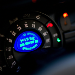
The gear selector, also known as the gear shift or transmission selector, is a crucial component in vehicles equipped with manual or automatic transmissions. Its primary function is to allow the driver to select the appropriate gear ratio for the engine’s power output and the vehicle’s speed, thereby optimizing performance and efficiency. In manual transmissions, the gear selector is often a lever that the driver operates to engage different gears, which requires a combination of clutch operation and shifting. This interaction enables the driver to control the vehicle’s acceleration and deceleration, making it essential for performance driving.
In contrast, automatic transmissions utilize a gear selector that often features a simpler interface, allowing the driver to choose from settings such as “Park,” “Reverse,” “Neutral,” and “Drive.” The automatic transmission system takes over the gear selection process by using hydraulic systems and electronic controls to shift gears based on factors like speed, Engine load, and throttle position.
Modern vehicles may incorporate advanced features in the gear selector, such as push-button or electronic selectors, which enhance convenience and may include safety features to prevent accidental gear engagement. Overall, the gear selector plays a vital role in a vehicle’s drivability, impacting not only performance but also safety and fuel efficiency. Its design and functionality have evolved significantly, reflecting advancements in automotive technology and driver preferences.

 and safety glasses to protect yourself while working.
 and supercharged engines, designed to regulate the amount of boost pressure generated by the forced induction system. The primary function of a boost controller is to manage the pressure of the intake
 and
and 
 and repeat the process until all valves are adjusted.
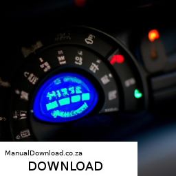
 and let it run for a few minutes. Check for any leaks around the new gasket and listen for any unusual sounds.
 and start the engine. Check for any warning lights on the dashboard related to the clutch system.
 and Install Components
 and fuel mixture entering the engine, thus controlling
 and procedures. If you are not confident in performing these repairs, it is advisable to seek