
Performing engine diagnostics on a BMW 328Ci E46 (produced between 1998 and 2006) can seem daunting if you have little mechanical experience, but it can be broken down into simpler steps. click here for more details on the download manual…..
- BMW 330xi Radiator Upgrade DIY (1999-2006 BMW E46 330i, 330Ci, 325i, 325xi, 325Ci, 328i, 328xi) Notorious for cooling system woes, the BMW E46 is just a few choice upgrades away from good reliability. One of the best things …
- Best first mod for your E46 For POV drive video with all these mods (great sound): https://youtu.be/7N_eKKEVMzg I installed ebay headers and aside from a …
Here’s a straightforward guide to help you understand the process.
### Tools You’ll Need:
1. **OBD-II Scanner**: This device reads diagnostic trouble codes (DTCs) from the car’s computer.
2. **Basic Hand Tools**: Screwdrivers, wrenches, and pliers (for minor repairs).
3. **Notebook and Pen**: To jot down any codes or observations.
### Step-by-Step Guide to Engine Diagnostics
#### 1. **Check Engine Light**
– Before diving into diagnostics, look for the **Check Engine Light** (CEL) on your dashboard. If it’s illuminated, this indicates that there’s an issue that needs to be addressed.
#### 2. **Locate the OBD-II Port**
– The OBD-II port is usually located under the dashboard, near the driver’s side, just above the pedals. It’s a small, rectangular connector.
#### 3. **Connect the OBD-II Scanner**
– Plug the scanner into the OBD-II port. Ensure your vehicle is off when you do this.
– Turn the ignition key to the “ON” position without starting the engine (you may need to press the start button if your model has one).
#### 4. **Read Diagnostic Codes**
– Follow the instructions on your OBD-II scanner to retrieve the codes.
– The scanner will display a series of codes; these are the Diagnostic Trouble Codes (DTCs) that indicate specific issues with the engine or other systems.
#### 5. **Interpret the Codes**
– Once you have the codes, look them up in the scanner’s manual or use online resources to understand what each code means. Common codes might relate to sensors, fuel systems, or ignition problems.
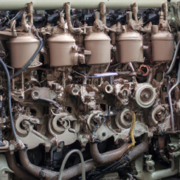
#### 6. **Visual Inspection**
– While you’re at it, perform a basic visual inspection of the engine bay:
– Look for any loose or damaged wires.
– Check for leaks (oil, coolant, etc.).
– Make sure all hoses are connected securely.
– Inspect belts for wear.
#### 7. **Research and Troubleshoot**
– Based on the codes retrieved and your visual inspection, research potential fixes. Forums for BMW enthusiasts can be helpful.
– Many issues can be resolved by replacing faulty sensors, cleaning parts, or tightening connections.
#### 8. **Clear Codes (if applicable)**
– After addressing the issues, you can clear the codes using your scanner. This will reset the CEL.
– Monitor the dashboard for the CEL to see if it returns. If it does, the issue may not have been fully resolved.
#### 9. **Test Drive**
– Take your car for a short drive to see if the CEL comes back on. This will help confirm whether the issue has been fixed.
### When to Seek Professional Help
If you retrieve codes that are complex or if the CEL returns after your efforts, it might be time to consult a professional mechanic. They have more specialized tools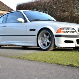 and expertise to diagnose and address serious issues.
### Conclusion
While engine diagnostics on a BMW 328Ci E46 can seem intimidating, following these steps can help you identify and possibly resolve issues. Always prioritize safety, and don’t hesitate to seek professional help if needed.
A fuel injector is a critical component of modern internal combustion engines, playing a vital role in the engine’s performance and efficiency. Its primary function is to deliver the precise amount of fuel into the combustion chamber at the correct time, ensuring optimal combustion. Unlike older carburetor systems, which mix air and fuel mechanically, fuel injectors use electronic controls to achieve a more accurate and efficient fuel-air mixture, enhancing overall engine performance.
Fuel injectors are typically composed of a nozzle, a solenoid or piezoelectric actuator, and a fuel passage. When the engine’s control unit (ECU) signals the injector, the actuator opens the nozzle, allowing fuel to spray into the intake manifold or directly into the combustion chamber, depending on the type of fuel injection system used—either port fuel injection (PFI) or direct fuel injection (DFI). The injector’s design allows for various spray patterns and atomization levels, which are crucial for ensuring complete combustion and minimizing emissions.
The performance of fuel injectors is influenced by several factors, including the fuel type, engine speed, and load conditions. Over time, injectors can become clogged or malfunction, leading to engine misfires, reduced fuel efficiency, and increased emissions. Regular maintenance and cleaning can help ensure injectors function optimally, making them essential for the longevity and efficiency of an engine. In summary, fuel injectors are fundamental components that enable engines to operate efficiently, meet regulatory standards, and provide the performance drivers expect.
 and does not pull to one side.
 and that there are no loose wires.
 and aligning the transmission.
 and the repair looks smooth. If it’s still visible or the
 and feel for any vibrations.
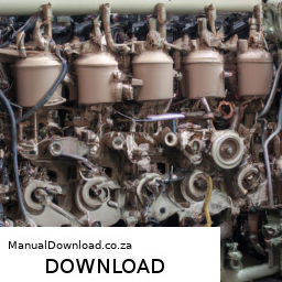
 and bolt it in securely.
 and listen for any unusual noises. Check to make sure the belt is running smoothly without any wobbling.
 and tighten the lug nuts properly.
 and torque specifications tailored to your vehicle.