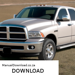
### Strut Mount Replacement on a Dodge Ram 2500 #### Tools and Materials Needed – **Jack and Jack Stands** – A hydraulic floor jack to lift the vehicle safely. click here for more details on the download manual…..
- RAM 2500 Cummins DIESEL vs GAS (6.4 Hemi) | Which Engine Should you Buy? *Diesel Mechanic Explain… I discuss whether a Diesel Engine (6.7 Cummins) or a Gas Engine (6.4 Hemi) is the better choice for you to buy in your pick up …
- RAM 2500 Cummins 6.7L Diesel Engine ** Heavy Mechanic Review** | TOP 3 ISSUES I reviewed a 2023 RAM 2500 Cummins 6.7 Diesel Engine as a heavy duty mechanic. I talk about potential engine issues and …
### Strut Mount Replacement on a Dodge Ram 2500
#### Tools and Materials Needed
– **Jack and Jack Stands**
– A hydraulic floor jack to lift the vehicle safely.
– Jack stands to securely support the vehicle once lifted, ensuring safety during the process.
– **Lug Wrench**
– Used to loosen and remove the lug nuts on the wheels. A cross-pattern wrench or a breaker bar may be helpful for stubborn nuts.
– **Socket Set**
– A metric socket set (typically 10mm to 21mm) for various bolts on the strut assembly. A ratchet and extension will ease access in tight spaces.
– **Torque Wrench**
– Essential for ensuring that all bolts are tightened to the manufacturer’s specifications to avoid any issues after installation.
– **Pry Bar**
– Useful for separating components that might be stuck together, especially under tension.
– **Spring Compressor**
– A tool designed to safely compress the coil spring on the strut assembly, allowing for safe removal and installation. Ensure to follow the manufacturer’s instructions for safe operation.
– **Strut Mounts**
– Replacement strut mounts specific to the Dodge Ram 2500. It’s advisable to purchase high-quality mounts to maintain performance and longevity.
– **Grease or Lubricant**
– To apply on the mounts and bolts for ease of installation and to prevent rust.
– **Safety Gear**
– Safety glasses and gloves to protect yourself from debris and sharp edges.
#### Procedure for Strut Mount Replacement
– **Preparation**
– Park the vehicle on a flat, stable surface. engage the parking brake to prevent movement.
– **Lift the Vehicle**
– Use the jack to lift the front of the vehicle, then place jack stands under the frame to secure it. Ensure the vehicle is stable before proceeding.
– **Remove the Wheel**
– Use the lug wrench to loosen and remove the lug nuts, then take off the wheel to access the strut assembly.
– **Access the Strut Assembly**
– Locate the top and bottom bolts of the strut. The top bolts are typically found under the hood, while the bottom bolts are connected to the lower control arm.
– **Remove the Lower Strut Bolt**
– Use the appropriate socket to remove the lower bolt first. You may need to use a pry bar to help separate the strut from the control arm if it’s stuck.
– **Compress the Coil Spring**
– Carefully place the spring compressors on the coil spring. Ensure they are evenly spaced and tightened according to the compressor’s instructions. This ensures the spring is compressed safely while working on the strut mount.
– **Remove the Upper Strut Mount Bolts**
– Open the hood and locate the top strut mount. Remove the retaining nuts using the socket set, and be cautious as the spring may push the strut upwards once released.
– **Remove the Strut Assembly**
– Once the upper bolts are removed, gently lower the strut assembly from the vehicle. Ensure that the spring is still securely compressed.
– **Replace the Strut Mount**
– Remove the old strut mount from the strut assembly. Clean any debris from the mounting area. Install the new strut mount by aligning it properly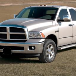 and securing it with the bolts.
– **Reassemble the Strut Assembly**
– Carefully raise the strut assembly back into position. Ensure that the new mount aligns with the holes in the body of the vehicle.
– **Tighten the Upper Bolts**
– Reinstall and tighten the upper strut mount bolts. Follow the manufacturer’s torque specifications closely.
– **Reinstall the Lower Strut Bolt**
– Position the strut into the lower control arm and insert the lower strut bolt, tightening it securely.
– **Remove the Spring Compressor**
– Once everything is secure, carefully remove the spring compressors, ensuring the strut and coil spring are stable.
– **Reinstall the Wheel**
– Place the wheel back onto the hub and hand-tighten the lug nuts. Lower the vehicle back to the ground and then use the torque wrench to tighten the lug nuts to the manufacturer’s specifications.
– **Final Checks**
– Before taking the vehicle for a test drive, double-check all fasteners, ensuring everything is secure. Take a moment to inspect the area for any tools or debris left behind.
– **Test Drive**
– Conduct a short test drive to ensure that everything feels normal and the new strut mounts are functioning correctly.
#### Safety Note
– Always exercise caution when working under a vehicle, and ensure your tools and equipment are in good condition to prevent accidents.
The fuel cap, often referred to as a gas cap, is a critical component of a vehicle’s fuel system. Its primary function is to seal the fuel tank, preventing fuel vapors from escaping into the atmosphere and protecting the tank’s contents from contaminants. Typically made from durable materials such as plastic or metal, the fuel cap is designed to withstand harsh environmental conditions, including extreme temperatures and exposure to fuel.
Fuel caps come in different designs, including screw-on caps, locking caps, and quick-release caps, each serving specific needs. Screw-on caps, which are most common, require the user to twist them to secure or release them from the fuel filler neck. Locking caps provide added security against fuel theft and tampering, while quick-release caps allow for faster refueling, often found in racing applications.
In addition to its sealing function, the fuel cap plays a crucial role in maintaining the vehicle’s fuel system pressure. A properly functioning cap ensures that the tank remains pressurized, which is essential for optimal fuel delivery to the engine. A malfunctioning or loose fuel cap can trigger warning lights on the dashboard and lead to reduced fuel efficiency, increased emissions, and potential engine performance issues. Therefore, regular inspection and maintenance of the fuel cap are vital for the overall health of a vehicle’s fuel system.

 tands to provide safe access to the underside.
 and fluid regularly to keep your car in good condition.
 and well-lit.
 and start the engine. Listen for any unusual noises. The belt should run smoothly without slipping or squeaking.
 and ensure that everything is working as it should.
 and add fluid if necessary.
 and the drain plug is closed.
 and press the clutch pedal to see if any warning lights are still on. If the sensor is functioning properly, the warning lights should go off.
 and torque specifications.