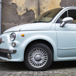
Replacing a coil spring on a Mercedes-Benz S-Class S300SEL W140 involves several steps. click here for more details on the download manual…..
- 1995 mercedes w140 s500 update and whats next
- Mercedes W140 300SE engine wiring harness rebuild
Here is a reverse order guide for the process:
### 7. Reassembly and Final Checks
– **Reinstall Wheels:** Place the wheels back on the vehicle and hand-tighten the lug nuts.
– **Lower the Vehicle:** Use the jack to lower the vehicle back to the ground.
– **Torque Lug Nuts:** Once the vehicle is on the ground, torque the lug nuts to the manufacturer’s specifications.
– **Reconnect Battery:** If you disconnected the battery, reconnect it.
### 6. Install the New coil Spring
– **Position the Spring:** Carefully position the new coil spring into the spring seat, ensuring it is seated properly in both the top and bottom mounts.
– **Compress the Spring:** If necessary, use a spring compressor to safely compress the spring for easier installation.
### 5. Reinstall Suspension Components
– **Attach Shock Absorber:** Reattach the shock absorber to the suspension arm and tighten the bolts to the specified torque.
– **Reattach Control Arms:** Reinstall any control arms or links that were removed during the process.
– **Install Any Additional Components:** Reconnect any other components, such as sway bar links or brackets, that were removed.
### 4. Remove the Old coil Spring
– **Detach Suspension Components:** Unbolt the shock absorber and any other components blocking access to the coil spring.
– **Remove the coil Spring:** Carefully remove the old coil spring from the spring seat. If it’s stuck, ensure all bolts and components are removed before attempting to take it out.
### 3. Prepare the Vehicle
– **Raise the Vehicle:** Use a jack to lift the vehicle and secure it on jack stands.
– **Remove the Wheels:** Take off the wheels to access the suspension components.
### 2. Gather Tools and Safety Equipment
– **Tools Needed:** You will need a jack, jack stands, lug wrench, socket set, wrench set, spring compressor, and safety equipment (gloves, goggles).
– **New coil Spring:** Ensure you have the correct replacement coil spring that meets OEM specifications.
### 1. Safety First
– **Park on a Level Surface:** Ensure the vehicle is parked on a flat, stable surface.
– **Engage the Parking Brake:** To prevent any movement, engage the vehicle’s parking brake.
– **Disconnect Battery (if necessary):** If you will be working near electrical components, consider disconnecting the battery for safety.
By following this reverse order guide, you can systematically approach the coil spring replacement process for a Mercedes-Benz S-Class S300SEL W140. Always refer to the vehicle’s service manual for specific torque specifications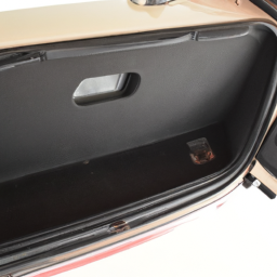 and safety procedures.
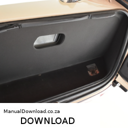
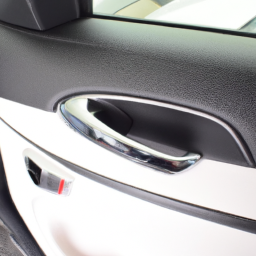
The vanity mirror light is a specialized lighting component commonly found in vehicles, particularly in the sun visors or overhead consoles, designed to illuminate the vanity mirror area for drivers and passengers. This feature is especially popular in vehicles aimed at enhancing comfort and convenience for occupants, allowing for better visibility when applying makeup, grooming, or making adjustments before stepping out of the car.
Typically, the vanity mirror light consists of one or more small light bulbs or LED lights, strategically positioned to provide even lighting without casting harsh shadows. The light is usually activated when the sun visor is flipped down or when the small mirror cover is opened, ensuring that it only illuminates when necessary, thus conserving energy.
In terms of design, vanity mirror lights are often designed to blend seamlessly with the vehicle’s interior aesthetics, offering a subtle yet functional addition. they can also come with additional features such as dimmability or color temperature adjustments, enhancing the user experience.
Moreover, the vanity mirror light plays a significant role in enhancing safety by allowing drivers and passengers to check their appearance without needing to exit the vehicle or rely solely on external lighting conditions. Overall, this unassuming component contributes to the overall functionality and user-friendliness of modern vehicles.
 and amount of
 rand Vitara.
 and procedures.
 and control arms.
 and any guide pins.
 and flywheel. Replace and hand-tighten the bolts that secure it to the flywheel.
 and Lower Hoses:** Reattach the upper and lower radiator hoses, ensuring the clamps are tight.
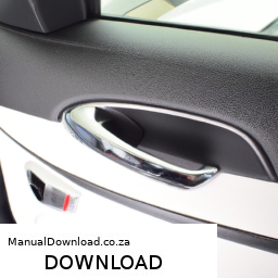
 and cleaner.
 and secure it with the screws or clips that you removed earlier.