Download 2008 Renault Scenic II Service and Repair Manual –

repair manual
Replacing the water pump on a Renault Scenic II can be a challenging task, especially for someone with little mechanical experience. click here for more details on the download manual…..


    Renault Scenic 2 inner CV joint and CV boot replacement In this video we will show how to remove and replace / change the inner CV joint and CV boot on Renault Scenic 2. 2003 Renault …

    Renault Scenic II reset service light, oil change reminder After changing oil & filter and performing maintenance service in your Renault Scenic II, you can reset the service message on the …

However, with some patience and careful attention to detail, it can be done. Here’s a simple step-by-step guide to help you through the process:

### Tools and materials Needed:
1. **Tools:**
socket set (including ratchet and extensions)
– Wrenches
– Screwdrivers (flathead and Phillips)
– Pliers
– Torque wrench
– Prying tool (optional)
– Gasket scraper (optional)

2. **Materials:**
– New water pump
– New timing belt (if necessary)
– New gasket or sealant (if required)
– Coolant (antifreeze)
– Shop towels or rags
– Container for old coolant

### Step-by-Step Guide:

#### 1. **Preparation:**
– **Safety First:** Park the vehicle on a flat surface and engage the handbrake. Wear safety glasses and gloves.
– **Disconnect the Battery:** Open the hood and disconnect the negative terminal of the battery to avoid any electrical issues.

#### 2. **Drain the Coolant:**
– **Locate the Drain Plug:** Find the radiator drain plug at the bottom of the radiator.
– **Drain the Coolant:** Place a container under the radiator and open the drain plug to let the old coolant flow out. Once drained, close the drain plug.

#### 3. **Remove Components to Access the Water Pump:**
– **Remove Engine Covers:** If there are any plastic covers on the engine, remove them using the appropriate tools.
– **Remove the Timing Belt (if necessary):** If your water pump is driven by the timing belt, you will need to remove it. this usually involves:
– Loosening the tensioner pulley and removing the belt.
– **Remove Accessories:** Depending on your model, you may need to remove parts like the alternator or air conditioning compressor to gain access to the water pump.

#### 4. **Remove the Old Water Pump:**
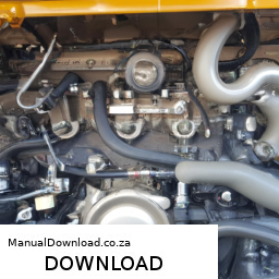
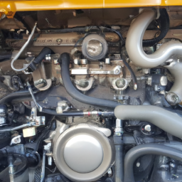
– **Locate the Water Pump:** It is typically located at the front of the engine, connected to the timing belt.
– **Unbolt the Water Pump:** Use your socket set to remove the bolts securing the pump. Keep track of the bolts, as you will need them for the new pump.
– **Remove the Old Pump:** Carefully pull the old pump off. You may need to gently pry it off if it’s stuck.

#### 5. **Install the New Water Pump:**
– **Clean the Surface:** Make sure the area where the new pump will sit is clean. Use a gasket scraper if necessary to remove any old gasket material.
– **Position the New Pump:** Place the new water pump onto the engine, ensuring it aligns correctly with the bolt holes.
– **Bolt it Down:** Hand-tighten the bolts first, then use the torque wrench to tighten them to the manufacturer’s specifications.

#### 6. **Reassemble Remaining Components:**
– **Reinstall the Timing Belt:** If you removed the timing belt, carefully reinstall it, ensuring it is aligned correctly.
– **Reconnect Accessories:** Reattach any components you had to remove, like the alternator or air conditioning compressor.
– **Replace Engine Covers:** Put back any plastic or metal covers you removed earlier.

#### 7. **Refill with Coolant:**
– **Pour in New Coolant:** Use a funnel to pour new coolant into the radiator. Make sure to use the correct type for your vehicle.
– **Bleed the System:** Run the engine with the radiator cap off until it reaches operating temperature, allowing any everything is reassembled, reconnect the battery.

#### 9. **Test the System:**
– **Start the Engine:** Start the car and let it run. Check for leaks around the water pump and ensure that the engine reaches normal operating temperature without overheating.

### Final Tips:
– **Take Your Time:** Don’t rush through the process. Take your time to ensure everything is done correctly.
– **Consult a Manual:** If you have access to a repair manual specific to the Renault Scenic II, it can provide valuable information on torque specifications and other details.
– **Seek Help if Needed:** If at any point you feel unsure, don’t hesitate to ask someone with more mechanical experience for assistance.

By following these steps carefully, you should be able to successfully replace the water pump on a Renault Scenic II. Good luck!
The master cylinder is a crucial component of a vehicle’s hydraulic brake system, responsible for converting the mechanical force applied to the brake pedal into hydraulic pressure. this pressure is then transmitted through brake lines to the wheel cylinders or calipers at each wheel, ultimately activating the braking mechanism. Typically constructed from aluminum or cast iron, the master cylinder houses one or more pistons that move within a cylindrical chamber when the brake pedal is pressed.

When the driver steps on the brake pedal, it pushes a rod connected to the master cylinder’s piston. this action compresses the brake fluid within the cylinder, creating hydraulic pressure. Most modern vehicles are equipped with a dual master cylinder system, which enhances safety by providing a backup in case one circuit fails. Each circuit operates independently, ensuring that at least some braking power remains even if one side of the system develops a leak.

The master cylinder also contains a reservoir for brake fluid, which is crucial for maintaining the proper fluid level and ensuring the system operates effectively. Regular maintenance of the master cylinder, including checking for leaks and ensuring the brake fluid is clean and at the correct level, is essential for safe vehicle operation. A malfunctioning master cylinder can lead to brake failure, making it vital for vehicle safety and performance.

Download Komatsu 107E-1 Series Diesel Engine Complete Workshop Service Repair Manual –

repairs
Replacing the gearbox synchronizer on a Komatsu 107E-1 engine is a complex procedure that requires careful attention to detail and the right tools. click here for more details on the download manual…..


    How to Find Your Komatsu SAA6D107E-1 Serial Number Having trouble finding your Komatsu 107E-1 serial number? Look no further. We know the trouble it can be to find your engine …

    Komatsu excavator fuel injector problem and solutions- black smoke from exhaust system #trending When it comes to a fuel injector problem in a Komatsu excavator, there are a few potential causes and solutions to consider: 1.

Below is a detailed guide on the steps and tools needed for this replacement.

### Tools and Equipment Needed

– **Socket Wrench Set**: A set of sockets in various sizes, including both metric and SAE, will be needed to remove bolts from the gearbox and related components.

– **Torque Wrench**: Essential for ensuring that bolts are tightened to the manufacturer’s specifications, preventing future issues.

– **Pliers and Wire Cutters**: Useful for handling clips, retaining rings, and any wiring that may be in the way.

– **Screwdrivers**: Both flathead and Phillips screwdrivers will be needed for various components and covers.

– **Gear Puller**: This tool aids in the removal of the synchronizer and other tight-fitting components without damaging them.

– **Seal Puller**: If seals need to be replaced, this tool helps to remove old seals without damaging the surrounding components.

– **Cleaning Supplies**: Degreaser, rags, and brushes will be needed to clean the gearbox and surrounding areas before reassembly.

– **Gasket Scraper**: Used to remove old gaskets from the mating surfaces of the gearbox.

– **New Gaskets and Seals**: Ensure you have the correct replacement parts for the gearbox to prevent leaks after reassembly.

– **Lubricant or Grease**: For applying to seals and moving parts during reassembly.

– **Service Manual**: A specific manual for the Komatsu 107E-1 will provide critical torque specifications and detailed diagrams.

### Steps for Gearbox Synchronizer Replacement

– **Preparation**:
– Ensure the engine is turned off and cool. Disconnect the battery to prevent any electrical issues during the process.

– **Access the Gearbox**:
– Remove any protective covers or panels that obstruct access to the gearbox. This may involve unscrewing various bolts and carefully lifting components away.

– **Drain Gearbox Oil**:
place a container beneath the gearbox and remove the drain plug to allow the oil to fully drain. This prevents spills during the replacement process.

– **Remove Gearbox**:
– Unscrew all bolts securing the gearbox to the engine. Support the gearbox with a jack or hoist as you remove the last bolts to prevent it from falling.

– **Disassemble Gearbox**:
– Carefully separate the gearbox casing. Use a gasket scraper to remove any old gaskets. Take note of the arrangement of internal components as you disassemble them.

– **Inspect Components**:
– Inspect all internal components for wear or damage. This includes gears, bearings, and the synchronizer itself. Replace any damaged components.

– **Remove Old Synchronizer**:
– Use a gear puller to carefully extract the old synchronizer from its housing. Be cautious not to damage surrounding components.

– **Install New Synchronizer**:
– Align the new synchronizer in its designated position. Ensure it is seated correctlydownload Komatsu 107E 1 Engine workshop manual and does not bind.

– **Reassemble Gearbox**:
– Carefully reassemble the gearbox in the reverse order of disassembly. Pay attention to the orientation of all components and ensure they are properly aligned.

– **Replace Gaskets and Seals**:
– Apply new gaskets and seals to prevent future leaks. Lubricate seals lightly to ease installation.

– **Reattach Gearbox**:
– Lift the gearbox back into position on the engine. Secure it with the appropriate bolts, tightening them in a crisscross pattern to ensure even pressure.

– **Refill Gearbox Oil**:
– Replace the drain plug and refill the gearbox with the recommended oil type and quantity as specified in the service manual.

– **Reconnect Battery**:
– Reconnect the battery and any electrical connections that were disconnected during the process.

– **Test Operation**:
– Start the engine and test the gearbox operation. Check for any unusual noises and ensure the synchronizer functions correctly.

– **Final Inspection**:
– After testing, inspect the area for any leaks or issues. Tighten any bolts if necessary.

### Conclusion

Replacing the gearbox synchronizer on a Komatsu 107E-1 engine requires meticulous planning and execution. Following these steps carefully and using the right tools will help ensure a successful replacement and optimal performance of the gearbox. Always refer to the service manual for specific instructions and torque specifications tailored to your machine.
The dashboard is a critical component of a vehicle’s interior, serving as the primary interface between the driver and the car’s various systems and controls. Located directly in front of the driver, the dashboard is designed to provide essential information about the vehicle’s performance and operational status. It typically houses a variety of instruments and displays, including the speedometer, tachometer, fuel gauge, temperature gauge, and warning lights. These instruments allow the driver to monitor key aspects of the vehicle, such as speed, engine revolutions, fuel levels, and potential issues that may arise.

In addition to these gauges, the dashboard often features controls for the climate control system, audio system, navigation, and other entertainment features. Many modern dashboards incorporate advanced technology, such as touchscreen interfaces, digital displays, and connectivity options for smartphones. This evolution has enhanced the driver’s experience, allowing for greater convenience and access to information.

Moreover, the design of the dashboard is not only functional but also aesthetic, contributing to the overall look and feel of the vehicle’s interior. Safety considerations are also paramount, with many dashboards designed to minimize injury during an accident. Overall, the dashboard plays a vital role in vehicle operation, safety, and comfort, making it an indispensable part of any automobile.

Download Mitsubishi Galant 1997 – 2001 Car Workshop Manual / Repair Manual / Service Manual access –

discount
To perform a fuel system cleaning on a Mitsubishi Galant, you can follow these steps in reverse order: ### Step 5: Reassemble and Test – **Reconnect the battery:** Reattach the negative terminal of the battery if it was disconnected. click here for more details on the download manual…..


    Mitsubishi Galant VR4 Clutch Replacement

    Pre-Owned 2001 Mitsubishi Galant Fremont NE 68025 Click here for price : http://SiemerAutoCenter.vshoc.com/top0i9?vin=4A3AA46G11E198621 We have been honored to serve the …

To perform a fuel system cleaning on a Mitsubishi Galant, you can follow these steps in reverse order:

### Step 5: Reassemble and Test
– **Reconnect the battery:** Reattach the negative terminal of the battery if it was disconnected.
– **Start the engine:** Turn on the engine and let it idle for a few minutes to ensure the cleaning solution has been fully distributed throughout the system.
– **Test drive:** Take the vehicle for a short test drive to observe any changes in performance.

### Step 4: Complete the Cleaning Process
– **Run the cleaning solution:** Follow the instructions provided with your fuel system cleaner. This usually involves pouring the cleaner into the fuel tank or using a specialized tool that allows you to introduce it directly into the fuel rail while the engine is running. Let it run for the recommended time.

### Step 3: Prepare the Cleaning Solution
– **Choose a fuel system cleaner:** Select a reputable fuel system cleaning solution designed for your Mitsubishi Galant.
– **Mix the cleaner (if required):** Some products may need to be mixed with fuel, while others can be used directly.

### Step 2: Access the Fuel System
– **Locate the fuel tank:** Depending on the method you choose, access the fuel tank or fuel rail. For direct fuel rail cleaning, you may need to gain access to the engine bay.
– **Remove fuel pump fuse (if applicable):** If you’re going to introduce a cleaner directly into the fuel system, you might need to remove the fuel pump fuse to stop the fuel flow while you connect the cleaning apparatus.

### Step 1: safety Precautions
– **Gather tools and materials:** You’ll need a fuel system cleaner, a funnel (if adding to the fuel tank), safety goggles, and gloves.
– **Ensure proper ventilation:** Work in a well-ventilated area to avoid inhaling fumes.
– **Safety gear:** Wear gloves and safety glasses to protect yourself from fuel and cleaning agents.

### Additional Tips:
– Consult your vehicle’s owner manual for specific guidance related to the fuel system.
– Consider professional cleaning services if you are unfamiliar with the process or if the fuel system has significant buildup or issues.

By following these steps in reverse order, you can effectively clean the fuel system of your Mitsubishi Galant to help improve performancedownload Mitsubishi Galant Car access workshop manual and efficiency.
The crankshaft sensor, also known as the crank position sensor, is a vital component in modern internal combustion engines. Its primary function is to monitor the position and rotational speed of the crankshaft, which is essential for the engine’s timing and overall performance. By providing real-time data about the crankshaft’s position, this sensor plays a crucial role in optimizing the engine’s fuel injection and ignition timing, ensuring that the engine runs efficiently and smoothly.

Typically located near the crankshaft, the sensor can be either a Hall-effect type or a magnetic inductive type. Hall-effect sensors use a magnetic field to detect the position of the crankshaft, while inductive sensors generate a voltage signal in response to the rotating crankshaft’s metal teeth. This information is relayed to the engine control unit (ECU), which processes the data and adjusts various parameters to maintain optimal engine performance.

A malfunctioning crankshaft sensor can lead to a range of issues, including poor engine performance, difficulty starting the vehicle, and even stalling. In some cases, it can trigger warning lights on the dashboard, indicating a problem with the engine management system. Regular maintenance and timely replacement of this sensor, when necessary, are crucial for ensuring the longevity and reliability of an engine. Overall, the crankshaft sensor is an essential component that contributes significantly to the efficient operation of an internal combustion engine.

Download Suzuki Forenza 2002-2008 Service Repair Manual –

diy
Adjusting the gear ratio on a Suzuki Forenza typically involves changing the differential gears or the transmission gearing. click here for more details on the download manual…..


    Turbocharged Suzuki Forenza Update Video! Just giving an update for what’s to come for our forenza buddy!

    2007 suzuki forenza coolant leak Just purchased this car 3 weeks ago haven’t had no problems with it it overheated once trying to determine what’s the cause of …

This is a complex task that should ideally be performed by a professional mechanic. However, if you’re looking for a general overview of how to approach this process in reverse order, here’s a simplified step-by-step guide:

### 5. Reassemble the Vehicle
– **Reinstall the Driveshaft**: If you removed the driveshaft to access the differential or transmission, reattach it securely.
– **Lower the Vehicle**: Use a jack to lower the vehicle back to the ground if it was elevated for the adjustment.
– **Reconnect Any removed Components**: Ensure all components that were disconnected for access are reconnected properly.

### 4. Adjust the Differential or Transmission
– **Install New Gears**: If you’re changing the differential gears, install the new ring and pinion gears according to the manufacturer’s specifications.
– **Set Backlash and Gear Mesh**: Adjust the backlash (the distance between the gears) to ensure they mesh correctly. Use a dial indicator for precision.
– **Check Gear Oil**: Ensure that the differential or transmission is filled with the appropriate gear oil.

### 3. Remove the Old Gears
– **Disassemble the Differential/Transmission**: If changing the differential gears, remove the differential cover and drain the fluid. For transmission adjustments, you may need to remove the transmission pan.
– **Take Out the Old Gears**: Carefully remove the old ring and pinion gears. Note how they are positioned, as this information will be crucial for installing the new ones.

### 2. Prepare for Adjustment
– **Gather Necessary Tools and Parts**: Ensure you have all required tools (sockets, wrenches, gear pullers) and the new gear set on hand.
– **Lift the Vehicle**: Use a jack and jack stands to safely lift the vehicle and secure it for access.

### 1. Diagnose the Need for Adjustment
– **Identify Gear Ratio Requirements**: Determine why you need to adjust the gear ratio (e.g., improved acceleration, fuel efficiency).
– **Research Gear Options**: Look into the gear ratios available for the Suzuki Forenza and choose the appropriate one based on your driving needs.

### Important Notes:
– **Professional Help Recommended**: Gear ratio adjustments can significantly impact vehicle performancedownload Suzuki Forenza workshop manual and drivability. It’s advisable to consult with or hire a professional mechanic.
– **Safety Precautions**: Always prioritize safety when working under a vehicle. Use proper tools and techniques to avoid injury.

Remember, this is a simplified overview and may not cover all specifics or nuances involved in the process for a Suzuki Forenza. Always refer to a repair manual or service guide for detailed instructions tailored to your vehicle model.
A temperature gauge is a crucial component found in vehicles, serving as an indicator of the engine’s operating temperature. This instrument plays a vital role in monitoring the temperature of the engine coolant, which circulates through the engine to dissipate heat generated during combustion. The temperature gauge is typically positioned on the dashboard, allowing the driver to easily observe the engine’s thermal status while driving.

The operation of the temperature gauge relies on a temperature sensor, usually located near the engine block or within the coolant passages. This sensor converts temperature readings into electrical signals that the gauge interprets and displays, often as a needle on a dial or a digital readout. Normal operating temperatures usually range between 180°F to 220°F (approximately 82°C to 105°C), depending on the vehicle and its engine design.

Monitoring the temperature gauge is essential for preventing engine overheating, which can lead to severe damage, including warped cylinder heads or complete engine failure. If the gauge indicates that the temperature is rising beyond the normal range, it serves as a warning for the driver to take immediate action, such as checking coolant levels, inspecting for leaks, or stopping the vehicle to allow the engine to cool. Overall, the temperature gauge is an indispensable tool for maintaining engine health and ensuring safe vehicle operation.

Download Audi A4 B5 2000 Factory Service Repair Manual –

book store
Performing a coolant flush on an Audi A4 B5 can be a straightforward task if you follow the steps carefully. click here for more details on the download manual…..


    Project Laser Beam – Audi B5 S4 AAN 5-Cylinder Swap Because Race Car 😎 Project Laser Beam 2000 Audi S4 B5 Mod List AAN 2.2L 20vt 5-Cylinder 200k+ Miles MTM Stage 1 Tune RS2 Exhaust Manifold …

    Audi A4 B5 – Check For These Issues Before Buying What problems await you after buying a used Audi A4 (B5) ‘1994–2001. Common problems associated with a used Audi A4 B5 …

A coolant flush helps remove old coolant and contaminants from the system, ensuring your engine stays cool and runs efficiently. Here’s a simple guide to help you through the process:

### Tools and Materials Needed:
1. **Coolant**: Make sure to use the correct type for your Audi (usually G12 or G13).
2. **Bucket or Drain Pan**: To catch old coolant.
3. **Hoses**: You might need a piece of garden hose.
4. **Wrench Set**: For removing the drain plug.
5. **Funnel**: For pouring new coolant.
6. **Gloves**: To protect your hands.
7. **Safety Glasses**: To protect your eyes.

### Steps to Perform a Coolant Flush:

1. **Prepare the Vehicle**:
– Ensure the engine is cool. Working on a hot engine can cause burns.
– Park the car on a flat surface and turn off the ignition.

2. **Locate the Drain Plug**:
– The drain plug for the coolant is usually located at the bottom of the radiator. Refer to your owner’s manual If you’re having trouble finding it.

3. **Drain the Old Coolant**:
– Place the bucket or drain pan under the radiator.
– Using the wrench, carefully loosen and remove the drain plug. Allow the old coolant to drain completely into the bucket.
– **Tip**: Be careful as coolant can be toxic to pets and the environment. Clean up any spills immediately.

4. **Flush the System**:
– After the old coolant has drained, you can flush the system with water to remove any remaining residue.
– Close the drain plug and fill the radiator with water using a funnel.
– Start the engine and let it run for about 10-15 minutes with the heater on full. This circulates the water through the engine and heater core.
– After running the engine, turn it off and let it cool down.

5. **Drain the Water**:
– Repeat the draining process to remove the flushing water. Ensure the drain pan is in place.

6. **Add New Coolant**:
– Once the system is drained, you can add new coolant. Make sure to use the correct type for your Audi.
– Close the drain plug again If you haven’t already.
– Using a funnel, carefully pour the new coolant into the radiator until it’s full. You may need to mix the coolant with water according to the manufacturer’s instructions.

7. **Bleed the cooling System**:
– To ensure there are no air pockets in the cooling system, you may need to bleed it.
– Locate the bleeder valve (if applicable) on the engine and open it slightly while continuing to fill the radiator. Keep an eye on the coolant level to prevent air from being trapped.
– Once coolant starts flowing from the bleeder valve, close it.

8. **Checkdownload Audi A4 B5 workshop manual and Test**:
– Start the engine again and let it idle for a few minutes. Check for leaks around the drain plug and hoses.
– Make sure the temperature gauge is normal, and the heater is blowing warm air.

9. **Dispose of Old Coolant**:
– Take the old coolant to a recycling center or an auto parts store that accepts used fluids. never pour it down the drain or on the ground.

### Final Notes:
– Always consult your owner’s manual for specific instructions and coolant specifications for your Audi A4 B5.
If you are unsure or uncomfortable performing this task, it’s always best to seek help from a professional mechanic.

By following these steps, you can successfully perform a coolant flush on your Audi A4 B5 and help keep your engine running smoothly!
The crankshaft sensor, also known as the crankshaft position sensor (CKP), is a critical component in modern internal combustion engines. Its primary function is to monitor the position and rotational speed of the crankshaft, which is essential for the engine’s timing and overall performance. By providing real-time data to the engine control unit (ECU), the crankshaft sensor plays a vital role in optimizing fuel injection, ignition timing, and various other engine functions.

Typically located near the crankshaft, the sensor uses magnetic or Hall-effect technology to detect the rotational position of the crankshaft. As the crankshaft turns, a reluctor wheel or notched disc attached to it interrupts the sensor’s magnetic field, generating a series of electrical pulses. These pulses are then sent to the ECU, which interprets the data to determine the crankshaft’s position and speed.

A malfunctioning crankshaft sensor can lead to a range of issues, including poor engine performance, stalling, difficulty starting, or even engine misfires. In some cases, it may trigger the check engine light on the dashboard, alerting the driver to potential problems. Given its importance in engine management, the crankshaft sensor is a key component in ensuring that the engine operates efficiently and meets emissions standards. Regular diagnostics and maintenance can help identify issues with this sensor, preventing further complications and enhancing overall vehicle reliability.

Download Daihatsu Cuore Mira 1998-2003 Workshop Repair Service Manual –

service manual
Replacing the timing chain on a Daihatsu Cuore Mira can be a bit challenging, especially if you have little mechanical experience. click here for more details on the download manual…..


    660 cc engine installed in daihatsu cuore

    Daihatsu Mira Move Rear Shock Upgrade This video is to show a basic rear shock upgrade for daihatsu Mira’s, Moves, covering L2, L5 and L6 models. The shocks used are …

However, I’ll break it down into simple steps to help you understand the process. Keep in mind that this is a general guide and you may want to consult a repair manual or a professional if you’re unsure.

### Tools and Materials Needed:

1. **Tools:**
– Socket set (with ratchet and extensions)
– Wrenches
– Screwdrivers (flathead and Phillips)
– Pliers
– Torque wrench
– Timing chain tool kit (if available)

2. **Materials:**
– New timing chain
– New timing chain tensioner (it’s often a good idea to replace this too)
– Engine oil (for lubrication)
– Gasket sealant (if needed)
– Clean rags

### steps to Replace the Timing Chain:

#### 1. **Preparation:**
– **Disconnect the Battery:** Always start by disconnecting the negative terminal of the battery to prevent any electrical issues.
– **Clear the Workspace:** Make sure you have enough space to work and keep your tools organized.

#### 2. **Remove the Necessary Components:**
– **Drain the Engine Oil:** Use a drain pan to catch the oil. Open the oil pan plug and let it drain completely.
– **Remove the Engine Cover:** Unscrew the bolts holding the engine cover in place and carefully take it off.
– **Remove Other Components:** Depending on your model, you may need to remove parts like the alternator, power steering pump, or radiator to access the timing chain. Keep track of where each bolt and part goes.

#### 3. **Access the Timing Chain:**
– **Remove the Timing Chain Cover:** Unscrew the bolts holding the timing chain cover. Gently pry it off, being cautious not to damage any gaskets.
– **Locate the Timing Chain:** You should now See the timing chain, the gears (sprockets), and the tensioner.

#### 4. **Mark the Current Position:**
– **Mark Alignment Points:** Use a marker to make alignment marks on the gears and chain. This will help you align everything correctly when you install the new chain.

#### 5. **Remove the Old Timing Chain:**
– **Loosen the Tensioner:** If your model has a tensioner, loosen it to relieve tension on the chain.
– **Remove the Chain:** Carefully take the old timing chain off the sprockets. If there are guides or other components, remove them as well.

#### 6. **Install the New Timing Chain:**
– **Position the New Chain:** Place the new timing chain onto the sprockets, aligning it with the marks you made earlier.
– **Reinstall the Tensioner:** Tighten the tensioner to ensure the chain is snug but not overly tight.

#### 7. **Reassemble Everything:**
– **Replace the Timing Chain Cover:** Use a new gasket or sealant if necessary, then screw the cover back on.
– **Reinstall Other Components:** Put back any parts you removed earlier, making sure everything is securely fastened.

#### 8. **Finish Up:**
– **Refill Engine Oil:** Pour new engine oil into the engine.
– **Reconnect the Battery:** Reattach the negative terminal.
– **Start the Engine:** Turn the engine ondownload Daihatsu Cuore Mira workshop manual and listen for any unusual noises. If everything sounds good, you’ve done it!

#### 9. **Check for Leaks:**
– After running the engine for a few minutes, check for any oil leaks around the timing chain cover.

### Important Tips:
– **Take Pictures:** If you’re unsure about where things go, take pictures as you disassemble. This can help you remember the order of assembly.
– **Work Slowly:** Don’t rush the process. Take your time to ensure everything is done correctly.
– **Consult a Manual:** If possible, refer to a repair manual specific to the Daihatsu Cuore Mira for detailed instructions and torque specifications.

### Safety Note:
If you’re ever in doubt about any step in this process, it’s best to consult a professional mechanic. Working on an engine can be complex, and ensuring everything is done right is crucial for the vehicle’s performance and safety.
A fan relay is an essential electrical component in a vehicle’s cooling system, primarily responsible for controlling the operation of the engine cooling fan. This component plays a crucial role in regulating engine temperature, ensuring optimal performance and preventing overheating, which can lead to severe engine damage.

The fan relay acts as an intermediary between the vehicle’s engine control unit (ECU) and the cooling fan. When the engine’s temperature reaches a predetermined threshold, the ECU sends a signal to the fan relay. The relay then closes the circuit, allowing electrical current to flow to the cooling fan, activating it to draw air through the radiator and dissipate heat. Conversely, when the engine cools down to a safe temperature, the ECU signals the relay to open the circuit, turning off the fan.

Fan relays are typically designed to handle high current loads, as cooling fans can draw significant power. They are constructed with durable materials to withstand the harsh conditions present in the engine bay, including exposure to heat, vibration, and moisture. A malfunctioning fan relay can lead to issues such as the cooling fan not operating when needed, which may result in engine overheating, or it may cause the fan to run continuously, draining the vehicle’s battery.

In summary, the fan relay is a vital component that ensures the efficient operation of the engine cooling system, contributing to the overall health and longevity of the vehicle’s engine. Regular checks and maintenance of this component can help prevent overheating issues and promote reliable vehicle performance.

Download AUDI Q7 2007 ElectricalService Repair Manual –

do your own repairs
Replacing the drive belt on an Audi Q7 may seem daunting if you have little mechanical experience, but I’ll break it down into simple steps. click here for more details on the download manual…..


    Audi Q7 Front Brake Pads Replacement Job || How to Change Brake Pads on Audi Q7 LIKE | SHARE | SUBSCRIBE Audi Q7 front brake Pads Replacement job || How to Change brake pads on audi Q7 #q7brakepads …

    Audi Q7 Dent removal(Metal Medic Slide Hammer Review) In this video I show you some awesome tools from Metal Medic as well as fix a dent on an Audi Q7 Door. All done 100% glue pull …

Before you start, make sure you have the necessary tools and a replacement belt. Here’s how to do it:

### Tools You’ll Need:
– Socket set (usually metric sizes)
– Wrench set
– Screwdrivers (flathead and Phillips)
– Belt tensioner tool (optional but helpful)
– Safety gloves
– Safety glasses

### Steps to Replace the Drive Belt:

1. **Safety First**:
– Park your Audi Q7 on a flat surface and turn off the engine.
– Allow the engine to cool down completely.
Disconnect the negative battery terminal to avoid any electrical issues.

2. **Access the Drive Belt**:
– Open the hood and locate the drive belt. It’s usually found at the front of the engine.
– You may need to remove any covers or components blocking access to the belt. Use a screwdriver or socket wrench to do this.

3. **Inspect the Belt**:
– Before removing the old belt, take a good look at it. make note of how it is routed around the pulleys. You can take a picture for reference if needed.

4. **Release Tension**:
– Locate the belt tensioner. This is a spring-loaded pulley that keeps the belt tight.
– Use a wrench or a belt tensioner tool to move the tensioner away from the belt. This will relieve tension on the belt, allowing you to remove it easily.

5. **Remove the Old Belt**:
– While holding the tensioner back, carefully slide the belt off the pulleys.
– Once the belt is off, release the tensioner back to its original position.

6. **Install the New Belt**:
– Refer to the picture or your memory to route the new belt around the pulleys in the same way the old belt was installed.
make sure the belt is seated properly on all pulleys.

7. **Reapply Tension**:
– Again, use the wrench or tensioner tool to move the tensioner away, and then slide the belt onto the tensioner pulley.
– Release the tensioner to apply tension to the new belt.

8. **Double-Check Everything**:
make sure the belt is properly aligned and seated on all pulleys.
– Check that everything is secure and that any covers you removed can be put back on.

9. **Reconnect the Battery**:
– Reconnect the negative battery terminal.

10. **Test the Installation**:
– Start the engine and observe the belt in motion. Listen for any unusual sounds and ensure the belt is running smoothly.

### Final Tips:
– If you’re unsure about any step, consult your Audi Q7’s owner’s manual or a repair guide specific to your model.
– If you encounter any difficulties, don’t hesitate to ask for help from someone with more mechanical experience or consider taking the vehicle to a professional mechanic.

By following these steps carefully, you can successfully replace the drive belt on your Audi Q7!
The oil helps to clean the engine by carrying away debris and sludge. Over time, however, this oil can become contaminated with particles such as dirt, metal shavings, and carbon deposits, which can lead to reduced engine performance and potential damage if not addressed.

The oil filter plays a vital role in maintaining the integrity of the engine oil. It typically consists of a cylindrical metal housing filled with a filtering material, often made of paper or synthetic fibers, which traps these harmful particles as the oil circulates through it. Most modern oil filters are designed to withstand high pressure and temperatures, ensuring they function effectively under the demanding conditions of an operating engine.

There are two main types of oil filters: full-flow and bypass filters. Full-flow filters are responsible for filtering all the oil before it enters the engine, while bypass filters filter a portion of the oil, allowing unfiltered oil to circulate when the filter becomes clogged. Regularly replacing the oil filter during oil changes is essential for maintaining engine health, as a clogged or dirty filter can restrict oil flow, leading to inadequate lubrication and potential engine failure. In summary, the oil filter is an indispensable component that ensures the longevity and efficiency of an engine by maintaining clean, effective lubrication.

Download 2009 PEUGEOT 206 Service and Repair Manual –

purchase
Replacing the radiator on a Peugeot 206 involves several steps. click here for more details on the download manual…..


    How to install light stock for dash cluster |#206#peugeot206|#قابکیلومترنورانی Hi I show you how to upgrade your current dashboard in your vehicle . Specifically in this video I show you on peg 206 .and it can …

    Used Peugeot 206 Reliability | Most Common Problems Faults and Issues What are the most common problems and breakdowns used Peugeot 206 1998 – 2009. Used vehicle, experience, issues, review …

Here’s a reverse order breakdown of the process:

### 7. Reconnect the Battery
– Reconnect the negative battery terminal to restore electrical power to the vehicle.

### 6. Refill the Coolant
– Fill the cooling system with the appropriate type and mixture of coolant. Make sure to bleed any air out of the system If necessary.

### 5. Reattach Hoses and Connections
– Reattach the upper and lower radiator hoses, ensuring they are secured with clamps. Also, reconnect any electrical connections, such as the fan or temperature sensor.

### 4. Install the New Radiator
– Carefully position the new radiator into place, ensuring it fits correctly into the mounts.
– Secure it in place with the bolts you removed earlier.

### 3. Remove the Old Radiator
– Disconnect the upper and lower radiator hoses by loosening the clamps and sliding the hoses off.
If applicable, remove any fan assemblies that are attached to the radiator.
– Unbolt the old radiator from its mountings and carefully extract it from the engine bay.

### 2. Prepare the Vehicle
– Ensure the engine is cool before starting the replacement process.
– Lift the vehicle If needed, and place it on jack stands for better access, especially If any underbody components need removal.

### 1. Drain the Coolant
place a drain pan under the radiator and open the drain plug to drain the coolant from the system.
If there is no drain plug, remove the lower radiator hose to let the coolant flow out.

### Additional Tips
– Always wear glovesdownload PEUGEOT 206 workshop manual and safety glasses when handling coolant, as it can be toxic.
– Dispose of the old coolant and radiator properly according to local regulations.
– Check for any leaks after reassembly and before driving the vehicle.

By following these steps in reverse order, you’ll have a clear understanding of how to replace the radiator on a Peugeot 206.
A tachometer is an essential instrument in automotive and industrial applications designed to measure the rotational speed of an engine or motor’s crankshaft, typically expressed in revolutions per minute (RPM). It serves as a vital tool for drivers and operators to monitor engine performance, providing real-time feedback on how hard the engine is working.

The tachometer works by receiving signals from the engine, often through a sensor that detects the rotation of the crankshaft or camshaft. this data is then converted into a readable display, which can be analog (with a needle and dial) or digital. The needle on an analog tachometer typically sweeps across a circular dial, while digital tachometers present the information numerically on a screen.

Understanding the tachometer reading is crucial for several reasons. Operating an engine at too high an RPM can lead to excessive wear and potential damage, while running at too low an RPM may result in inefficient performance and increased emissions. Thus, the tachometer helps drivers optimize their gear shifts, maintain fuel efficiency, and ensure the longevity of the engine.

In performance driving, the tachometer becomes even more critical, allowing drivers to maximize acceleration and power output by shifting gears at the optimal RPM range. Overall, the tachometer is a fundamental component of any vehicle’s instrumentation, contributing significantly to safe and efficient driving.

Download 2019 BMW 840d xDrive (G16) 8 Series Gran Coupe OEM Download Service & Repair Manual Software –

diy
Performing a wheel alignment on a BMW 840d xDrive G16 8 Gran Coupe requires careful attention to detail and specific tools. click here for more details on the download manual…..


    2020 BMW M850i xDrive Gran Coupe – Luxury Four-Door Coupe 2020 BMW M850i xDrive Gran Coupe G16 – Drive, Interior and Exterior. Subscribe. #M850ixDriveGranCoupe …

    How to configure your BMW Kidney Grille and get that Iconic Glow Learn how to use BMW Iconic Glow The BMW Iconic Glow is connected to your Welcome Lights and can be configured in the …

Here’s a reverse order explanation of the process:

### 7. Final Adjustments
– Ensure that all adjustments are locked in place.
– Re-check alignment readings to confirm that they are within the manufacturer’s specifications.

### 6. Test Drive
– Take the vehicle for a test drive to check for any steering pull or handling issues.
– Return to the alignment rack to verify that the settings remain correct after the test drive.

### 5. Torque Specifications
– Tighten all adjustment bolts to the manufacturer’s torque specifications to ensure they do not loosen over time.

### 4. Adjust Angles
– Adjust the camber, caster, and toe angles as needed using the alignment machine’s readings.
– Typically, the front toe is adjusted first, followed by camber and caster If necessary.

### 3. Set Up Alignment Equipment
– Position the vehicle on the alignment rack.
– Attach the alignment heads to each wheel and connect them to the alignment machine.
– Ensure the vehicle is level and not under any load.

### 2. Inspect Suspension Components
– Check for any worn or damaged suspension parts (e.g., bushings, tie rods, control arms) that could affect alignment.
– Replace or repair any faulty components before proceeding with the alignment.

### 1. Prepare the Vehicle
– Ensure the vehicle is in a neutral position with the steering wheel straight.
– Check tire pressure and ensure all tires are at the recommended specifications.
– Remove any unnecessary weight from the vehicle.

### Note:
Always refer to the specific service manual for the BMW 840d xDrive G16 for detailed procedures, specifications,download BMW 840d xDrive G16 8 Gran Coupe OEM workshop manual and safety precautions tailored to that model. Proper training and equipment are essential for performing wheel alignments accurately.
The ignition switch is a crucial component in a vehicle’s electrical system, responsible for starting the Engine and controlling various electrical functions. Typically located on the steering column or the dashboard, the ignition switch serves as the interface between the driver and the vehicle’s ignition system. When the driver turns the key (or presses a button in keyless systems), the ignition switch activates the electrical circuit that allows power to flow to the ignition system and other essential components.

The ignition switch usually has several positions: “Off,” “Acc” (accessory), “On,” and “Start.” In the “Off” position, all electrical systems are powered down, conserving battery life. The “Acc” position enables the driver to use electrical accessories, like the radio or power windows, without starting the engine. When turned to the “On” position, the ignition switch powers the vehicle’s electrical systems, including the dashboard lights and fuel pump, while the “Start” position engages the starter motor, cranking the Engine to initiate combustion.

Modern ignition switches may incorporate advanced technology, such as transponder keys or push-button start systems, enhancing security and convenience. A malfunctioning ignition switch can lead to starting issues, electrical failures, or even potential safety hazards, making it a vital component for the overall functionality and reliability of a vehicle. Regular maintenance and timely replacement when issues arise are essential for ensuring seamless vehicle operation.

Download DAEWOO LEGANZA Service Repair Manual –

bookshop
Replacing the strut mounts on a Daewoo Leganza can seem daunting, but with some patience and the right tools, you can do it yourself! click here for more details on the download manual…..


    Daewoo Leganza – Check For These Issues Before Buying What problems await you after buying a used Daewoo Leganza (V100) (1997-2002)

    Restoration of old Daewoo car gearbox | Guide to repair and restore old car gearbox 5-speed Restoration of old Daewoo car gearbox | Guide to repair and restore old car gearbox 5-speed Continue to work with the gearbox …

Here’s a step-by-step guide to help you through the process. Remember to take safety precautions and work in a well-ventilated area.

### Tools and Materials Needed:
– Socket set
– Wrench set
– Screwdrivers (flat and Phillips)
– Jack and jack stands
– Spring compressors (optional, but recommended)
– Replacement strut mounts
– Torque wrench (optional, but helpful)
– Safety glasses and gloves

### Step-by-Step Guide:

1. **Safety First**:
– Make sure you wear safety glasses and gloves.
– Park the vehicle on a flat surface, turn off the engine, and engage the parking brake.

2. **Lift the Vehicle**:
– Use a jack to lift the front of the vehicle.
– Secure it with jack stands to ensure it stays elevated while you work.

3. **Remove the Wheel**:
– Use a socket or wrench to loosen and remove the lug nuts on the front wheel.
– Take off the wheel and set it aside.

4. **Locate the Strut Mount**:
– The strut mount is located at the top of the strut assembly, which is connected to the vehicle’s body.

5. **Remove the Strut Assembly**:
– Locate the bolts securing the strut to the lower control arm. Remove these bolts using a socket or wrench.
– Next, locate the three bolts at the top of the strut (under the hood) that hold the strut mount in place. Remove these bolts.
– Carefully pull the strut assembly out from the wheel well.

6. **Compress the Spring (If Necessary)**:
– If your strut has a coil spring, you may need to compress it using spring compressors to Safely remove the strut mount. Follow the instructions on the spring compressors carefully.
– If you’re not comfortable using spring compressors, consider getting help from a professional.

7. **Remove the Old Strut Mount**:
– With the coil spring Safely compressed, locate the strut mount at the top of the strut.
– Remove the nuts or bolts holding the strut mount in place. Take off the old strut mount.

8. **Install the New Strut Mount**:
– Place the new strut mount onto the strut assembly, aligning it with the holes.
– Secure it with the nuts or bolts you removed earlier. Make sure it’s tight.

9. **Reassemble the Strut Assembly**:
– If you used spring compressors, carefully release them once everything is secured.
– Reinsert the strut assembly back into the wheel well, securing it to the lower control arm and the top mount.

10. **Reattach the Wheel**:
– Place the wheel back on, hand-tighten the lug nuts, and then use a wrench to tighten them in a crisscross pattern.

11. **Lower the Vehicle**:
– Carefully remove the jack sdownload DAEWOO LEGANZA workshop manualtands and lower the vehicle back to the ground.

12. **Final Checks**:
– Once the vehicle is on the ground, use a torque wrench to tighten the lug nuts to the manufacturer’s specifications.
– Double-check that everything is securely fastened.

13. **Test Drive**:
– Take a short drive to ensure everything feels right. Listen for any unusual noises that might indicate something isn’t installed correctly.

### Conclusion:
And that’s it! You’ve successfully replaced the strut mounts on a Daewoo Leganza. If you encounter any difficulties or feel unsure at any point, don’t hesitate to ask for help from someone with more mechanical experience or consult a professional. Good luck!
A transmission cooler is an essential component in an automobile’s drivetrain system, specifically designed to regulate the temperature of the transmission fluid. The primary purpose of the transmission cooler is to prevent transmission overheating, which can lead to inefficient performance, increased wear and tear, or even catastrophic failure of the transmission system.

Transmission coolers are typically found in vehicles equipped with automatic transmissions, as these systems generate more heat compared to manual transmissions due to their complex hydraulic operations. The cooler is often a small radiator-like device that operates similarly to an engine radiator. It is usually mounted in front of the vehicle’s main radiator, where it can take advantage of the airflow created when the vehicle is in motion.

The cooler works by circulating the transmission fluid through a series of tubes or fins, allowing it to dissipate heat into the surrounding air. As the fluid passes through the cooler, it loses heat, making it cooler before it returns to the transmission. This process is crucial because proper transmission fluid temperature is vital for optimal performance and longevity of the transmission.

Overheating can lead to problems such as slipping gears, erratic shifting, or outright failure. By maintaining appropriate fluid temperatures, a transmission cooler enhances the overall efficiency and reliability of the vehicle, ensuring smoother operation and extending the lifespan of the transmission system. Additionally, many aftermarket transmission coolers are available for performance vehicles or those used for towing, providing an extra layer of protection against heat-related damage.