Download 2019 BMW 230i (F22) LCI 2 Series OEM Download Service & Repair Manual Software –

stores
Replacing the water pump on a BMW 230i F22 LCI requires careful attention to detail and proper tools. click here for more details on the download manual…..


    Unlock this Hidden Feature in Your BMW

    BMW DOESNT WANT YOU TO KNOW THIS! Must Watch 💥

Below are the steps and tools needed for the replacement process:

### tools Needed:

– **Socket Set**: A standard and deep socket set (8mm to 16mm) for various bolts.
– **Torque Wrench**: To ensure bolts are tightened to the manufacturer’s specifications.
– **Ratchet and Extensions**: For accessing bolts in tight spaces.
– **Pliers**: To remove hose clamps and other small components.
– **Screwdrivers**: Both flathead and Phillips for various screws.
– **Coolant Catch Pan**: To catch any leaking coolant during the removal process.
– **Funnel**: For pouring new coolant.
– **Gasket scraper or Razor Blade**: To remove old gasket material from the water pump mating surface.
– **Shop Towels/Rags**: For cleaning and wiping up spills.
– **Safety Goggles and Gloves**: To protect yourself while working.
– **New Water Pump**: OEM replacement part.
– **New Gasket or Sealant**: To ensure a proper seal on the new water pump.

### replacement Steps:

– **Preparation**:
– Park the vehicle on a level surface and turn off the engine. Allow it to cool completely.
– Disconnect the battery by removing the negative terminal to prevent any electrical issues.

– **Drain Coolant**:
– Place the coolant catch pan under the radiator.
– Open the radiator drain valve and allow the coolant to flow into the pan completely. This step is crucial to prevent spills when removing the water pump.

– **Remove Engine Cover**:
– If applicable, remove the engine cover by unscrewing any bolts or clips holding it in place.

– **Remove Components Blocking Access**:
– Remove any hoses or components that obstruct access to the water pump. This may include the air intake duct, throttle body, and any necessary brackets.

– **Disconnect the Water Pump Hoses**:
– Use pliers to loosen and remove the hose clamps from the hoses connected to the water pump. Carefully pull the hoses off the pump to avoid damaging them.

– **Remove the Water Pump**:
– Unscrew the bolts securing the water pump to the engine block using the appropriate socket size. Keep track of the bolt locations as they may vary in length.
– Gently pull the water pump away from the engine. If it’s stuck, lightly tap it with a rubber mallet to break the seal.

– **Clean the Surface**:
– Use a gasket scraper or razor blade to clean any old gasket material or sealant from the engine block’s mating surface. Ensure the surface is smooth and free of debris.

– **Install the New Water Pump**:
– Place the new gasket onto the new water pump, ensuring proper alignment with bolt holes.
– Position the new water pump onto the engine blockdownload BMW 230i F22 LCI 2 OEM workshop manual 
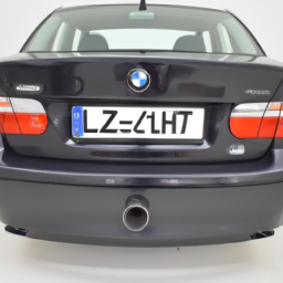
and hand-tighten the bolts to hold it in place.
– Use the torque wrench to tighten the water pump bolts in a crisscross pattern to the manufacturer’s specifications.

– **Reconnect Hoses**:
– Reattach the hoses to the new water pump and secure them with the hose clamps. Ensure a snug fit to prevent leaks.

– **Reinstall Components**:
– Reinstall any components that were removed to access the water pump, including the air intake duct and throttle body.

– **Refill Coolant**:
– Using a funnel, refill the cooling system with the appropriate type and mixture of coolant. Make sure to follow the manufacturer’s specifications.

– **Bleed the Cooling System**:
– Start the engine and allow it to reach operating temperature. This will help to circulate the coolant and remove any air pockets in the system. Keep an eye on the temperature gauge.
– If your model has a bleed screw, open it to allow trapped air to escape.

– **Final Checks**:
– Check for any leaks around the new water pump and hoses once the engine is running.
– Reconnect the battery and check all electrical connections.

– **Dispose of Old Coolant Properly**:
– Ensure you dispose of the old coolant and any used materials in accordance with local regulations.

### Conclusion:

– After ensuring that everything is secure and there are no leaks, take the vehicle for a short drive to confirm that the cooling system functions properly. Regularly check the coolant level and monitor for any signs of leaks over the next few days.
The grille emblem, often referred to as the front emblem or badge, is a prominent automotive component typically located at the center of a vehicle’s front grille. This emblem serves multiple purposes, combining aesthetic appeal with brand identity and functionality. Traditionally, it features the manufacturer’s logo or insignia, which can be a symbol, name, or stylized design representing the car brand. The grille emblem is one of the first elements that people notice, making it crucial for brand recognition and establishing the vehicle’s character.

From a design perspective, grille emblems have evolved significantly over the years. They can vary widely in size, shape, and material, often crafted from metals, plastics, or a combination of both. High-end vehicles might utilize chrome or even illuminated emblems, enhancing the visual impact, especially during nighttime driving. In some cases, grille emblems are designed to integrate seamlessly with the vehicle’s styling, contributing to the overall aerodynamic and aesthetic design of the front fascia.

Functionally, the grille emblem can also serve as a mounting point for sensors or cameras in modern vehicles, particularly with the rise of advanced driver-assistance systems (ADAS). Additionally, in some designs, the emblem may act as a cover for access points, such as the front hood latch. Overall, the grille emblem is a multifaceted component that plays a significant role in both the vehicle’s identity and its functional design.

Download 2012 BMW 320d (E91) 3 Series Touring OEM Download Service & Repair Manual Software –

stores
Certainly! click here for more details on the download manual…..


    BMW DOESNT WANT YOU TO KNOW THIS! Must Watch 💥

    Hidden Dash camera for BMW 1 2 3 4 5 6 7 x1 x2 x3 x4 x5 x6 Series intallation FITCAMX Dash Camera for Cars BMW 1 2 3 4 5 6 7 x1 x2 x3 x4 x5 x6 Series Hidden Car Camera with Front Lens 1080P FHD 170 …

Replacing suspension bushings on a BMW 320d E91 3 Touring involves several steps and tools. Below is a detailed guide with bullet points that outlines the process:

### Tools and Equipment Needed
– **Jack and Jack Stands**: To lift the vehicle securely and allow access to the suspension components.
– **Wheel Chocks**: To prevent the vehicle from rolling while lifted.
– **Lug Wrench**: For removing the wheel nuts.
– **Socket Set**: Including various sizes (typically 10mm to 19mm) for removing bolts.
– **Wrench Set**: To complement the socket set and access tight spaces.
– **Torque Wrench**: To ensure bolts are tightened to manufacturer’s specifications.
– **Pry Bar**: For leverage when removing old bushings.
– **Hammer**: To help with the removal of stubborn parts.
– **Bushing Removal Tool/Press**: A specialized tool for removing and installing bushings without damaging surrounding components.
– **Grease**: For lubricating the new bushings during installation.
– **Safety Goggles and Gloves**: For personal protection during the job.
– **Work Light**: Provides visibility in low-light conditions.

### Replacement Procedure
– **Preparation**:
– Park the vehicle on a flat surface and engage the parking brake.
– Place wheel chocks behind the rear wheels to prevent movement.

– **Lifting the Vehicle**:
– Use the jack to lift the front or rear of the vehicle, depending on which bushings you are replacing.
– Secure the vehicle with jack stands to ensure stability while working underneath.

– **Removing the Wheels**:
– Use the lug wrench to remove the wheel nuts and take off the wheels. this will provide access to the suspension components.

– **Identifying the Bushings**:
– Locate the suspension components where the bushings are situated. Common areas include control arms, subframes, and anti-roll bars.

– **Removing Old Bushings**:
– **Loosen Bolts**: Use the socket and wrench set to loosen and remove the bolts securing the bushings in place. this may involve multiple bolts on the control arms or subframe.
– **Use a Pry Bar**: If the bushing is stuck, use a pry bar to gently pry it out. Be cautious not to damage surrounding components.
– **Bushing Removal Tool**: If available, use a bushing removal tool to press out the old bushings. this tool will help avoid damage to the suspension components.

– **Preparing for New Bushings**:
– Clean the mounting surfaces where the new bushings will be installed. Remove any debris or old grease.
– Inspect the area for any signs of wear or damage that may need addressing.

– **Installing New Bushings**:
– Apply a thin layer of grease to the new bushings to facilitate installation and prevent squeaking.
– Use the bushing installation tool to press in the new bushings. Ensure they are seated properly in the mounting location.
– If a tool isn’t available, carefully tap the new bushing into place with a hammer, ensuring it is aligned correctly.

– **Reinstalling Suspension Components**:
– Position the control arm or other components back into placedownload BMW 320d E91 3 Touring OEM workshop manual and align the holes for the bolts.
– Insert and hand-tighten the bolts to hold the components in place.
– Use the torque wrench to tighten all bolts to the manufacturer’s specified torque settings.

– **Reattaching Wheels**:
reinstall the wheels and hand-tighten the lug nuts.
– Lower the vehicle back to the ground and then torque the wheel nuts to the manufacturer’s specifications.

– **Final Checks**:
– Check the suspension components to ensure everything is securely in place.
– Take the vehicle for a short test drive to ensure everything is functioning correctly and to listen for any unusual noises.

### Safety Tips
always wear safety goggles and gloves to protect yourself from debris and sharp objects.
– Make sure the vehicle is securely supported on jack stands before working underneath it.
– Be mindful of the torque specifications to avoid over-tightening or under-tightening bolts.

This guide provides a comprehensive overview of the tools, procedures, and safety precautions necessary for replacing suspension bushings on a BMW 320d E91 3 Touring. always refer to a repair manual specific to your vehicle for detailed specifications and torque settings.
A heat shield is a critical component in automotive design, primarily employed to protect various parts of a vehicle from excessive heat generated by the engine and exhaust system. Typically made from materials with high thermal resistance, such as aluminum, stainless steel, or specialized heat-resistant composites, heat shields are strategically positioned in areas where heat exposure could lead to damage or reduced performance.

The primary function of a heat shield is to deflect or absorb heat away from sensitive components, such as electrical wiring, fuel lines, and other plastic or rubber parts that could be compromised by high temperatures. this is essential not only for the longevity of these components but also for the overall safety and efficiency of the vehicle. Overheating can lead to failures, fires, or even hazardous leaks of fuel or fluids, making the heat shield a vital safety feature.

Heat shields can be found in various forms, including rigid plates, flexible mats, and even wrap around headers or exhaust pipes. In addition to their protective role, heat shields can also contribute to the vehicle’s thermal management system, helping maintain optimal operating temperatures for the engine and other systems. By enhancing thermal efficiency, heat shields play a crucial role in improving overall vehicle performance, fuel efficiency, and emissions control, thereby aligning with modern automotive standards and environmental regulations.

Download 2005 Subaru Impreza Edm Service & Repair Manual –

buy
Replacing the valve body on a Subaru Impreza involves several steps, and it’s important to approach this task carefully to ensure proper functionality. click here for more details on the download manual…..


    Subaru Impreza Gearbox OIl change 5 speed flushing out old oil been in for over 10years then will re do the process with high end oil.

    Subaru Impreza WRX STI Spec C | Spy Video | Edmunds.com If the number of letters in its name is at all proportionate with its level of improvements, the 2010 Subaru Impreza WRX STI Spec C …

Here’s a reverse order breakdown of the process:

### 10. Reinstall Transmission Pan
– **Clean the surfaces**: Ensure the mating surfaces of the transmission and pan are clean.
– **Install the new gasket**: Place a new gasket on the pan.
– **Bolt down the pan**: Secure the transmission pan with bolts, tightening them in a criss-cross pattern to ensure even pressure.

### 9. Reconnect Electrical Connectors
– **Reattach the connectors**: Plug back any electrical connectors that were removed during disassembly.
– **Check for proper connection**: Ensure all connections are secure and free from dirt or debris.

### 8. Install the New Valve Body
– **Position the valve body**: Carefully lower the new valve body into place, aligning it with the transmission housing.
– **Secure the valve body**: tighten the bolts that hold the valve body to the transmission, following the manufacturer’s torque specifications.

### 7. Remove Old Valve Body
– **Disconnect linkage and wiring**: Remove any linkage or wiring connected to the valve body.
– **Unscrew the valve body bolts**: Carefully take out the bolts holding the valve body in place and gently lift the old valve body out.

### 6. Drain Transmission Fluid
– **Place a drain pan underneath**: Set up a drain pan to catch old transmission fluid.
– **Remove the drain plug**: If applicable, remove the transmission fluid drain plug to drain the fluid.

### 5. Remove Transmission Pan
– **Unbolt the pan**: Take out the bolts securing the transmission pan and carefully lower it.
– **Drain any remaining fluid**: Allow any additional fluid to drain out of the pan.

### 4. Raise the Vehicle
– **Use jack stands**: Securely elevate the vehicle using jack stands to access the transmission underneath.
– **Ensure safety**: Make sure the vehicle is stable before working underneath it.

### 3. Gather Tools and Parts
– **Required tools**: Have a socket set, wrench set, torque wrench, and other necessary tools ready.
– **New valve body**: Obtain the correct replacement valve body for your Subaru Impreza.

### 2. Prepare the Workspace
– **Clean the area**: Ensure that your workspace is clean and free of debris.
– **Gather safety equipment**: Use glovesdownload Subaru Impreza Edm workshop manual and safety glasses for protection.

### 1. Disconnect the Battery
– **Remove the negative battery terminal**: This is crucial for safety before working on any electrical components.

### Additional Tips:
– Always consult the vehicle’s service manual for specific instructions and torque specifications.
– Consider professional assistance if unsure about any steps in the process.
– Ensure you have the correct replacement parts specific to your model year and transmission type.

By following these steps in reverse order, you’ll have a clear understanding of the valve body replacement process for a Subaru Impreza.
A battery hold down is a crucial component in a vehicle’s battery management system, specifically designed to secure the automotive battery in place within its designated tray or compartment. This component is particularly important for maintaining the stability and safety of the battery, especially in vehicles that experience frequent vibrations and movements, such as during driving or off-road conditions.

Typically made from materials like steel or high-strength plastic, the battery hold down features a bracket or strap that tightly secures the battery to prevent any movement. This is essential because any displacement of the battery can lead to damage to the battery terminals, potential short circuits, or even leaks of battery acid, which can be hazardous to both the vehicle and its occupants.

In addition to providing physical security, the battery hold down also plays a role in facilitating proper battery operation. A securely held battery ensures that the internal components remain aligned and function effectively, helping to maintain electrical connections and optimize performance. Furthermore, it can prevent the battery from coming into contact with other metal components of the vehicle, which could lead to electrical issues or corrosion.

Overall, the battery hold down is a small yet vital component that contributes to the overall functionality, safety, and longevity of an automotive battery, ensuring reliable performance throughout the vehicle’s lifespan.

Download 2012 TOWN and COUNTRY Service and Repair Manual –

sale
Replacing coil springs on a Chrysler Town & Country involves several steps and requires specific tools. click here for more details on the download manual…..


    town and country turbo!!!!!!!!!!!! lots of mini vans lol plus the silver bullet 🙂

    What is the Difference Between New York City, Long Island, and Manhattan? #newyork #geography #u… history #conflict #demographics #map #coutry #countrys #power #us #america #manhattan #city #newjersey #unitedstates.

Here’s a detailed guide:

– **Safety First**
– **Personal protective Equipment (PPE):** Wear safety glasses and gloves to protect yourself from debris and sharp edges.
– **Vehicle Stability:** Ensure the vehicle is parked on a flat surface. Use wheel chocks to prevent movement.
– **Disconnect Battery:** Remove the negative terminal of the battery to prevent any electrical issues while working on the vehicle.

– **Tools and Equipment Needed**
– **Jack and Jack Stands:** A hydraulic floor jack to lift the vehicle and jack stands to secure it safely.
– **Lug Wrench:** To remove the wheel lug nuts.
– **Socket Set:** A complete set of sockets and ratchets (including extensions) to remove suspension components.
– **Wrench Set:** A set of wrenches to assist with various bolts.
– **Coil Spring Compressor:** A specialized tool that compresses the coil spring, allowing for safe removal and installation.
– **Pry Bar:** To help with the removal of components that may be stuck.
– **Torque Wrench:** To ensure bolts are re-tightened to the manufacturer’s specifications.
– **Marker or Paint Pen:** To mark positions of components for reference during reassembly.

– **Preparation Steps**
– **Lift the Vehicle:** Use the jack to lift the front or rear of the vehicle, depending on which coil spring you are replacing. Secure with jack stands.
– **Remove the Wheel:** Use the lug wrench to take off the wheel on the side you are working on. This provides access to the suspension components.

– **Removing the coil Spring**
– **Disconnect Suspension Components:**
– Remove the nuts and bolts securing the strut assembly to the steering knuckle and the upper mount. This may require a socket and wrench.
– If necessary, separate the tie rod end and sway bar link for better access.
– **Use coil Spring Compressor:**
– Place the coil spring compressor on the coil spring and tighten it evenly until the spring is compressed. This is crucial for safety.
– Check that the compressor is securely holding the spring before proceeding.
– **Remove the Strut Assembly:**
– With the coil spring compressed, carefully unbolt the strut from its mount and remove it from the vehicle. Be cautious as the spring is under tension.

– **Spring Replacement**
– **Remove Old coil Spring:**
– Once the strut assembly is on a workbench, remove the old coil spring by unbolting it from the strut using a socket.
– **Install New coil Spring:**
– Position the new coil spring onto the strut assembly, ensuring it is seated properly.
– Use the coil spring compressor again to secure the new spring in place.

– **Reinstallation**
– **Reattach Strut Assembly:**
– Carefully lift the strut assembly back into position. Reattach it to the upper mountdownload TOWN COUNTRY workshop manual and lower control arm.
– Use the torque wrench to tighten all bolts to the manufacturer’s specifications.
– **Reconnect Suspension Components:**
– Reattach the tie rod end and sway bar link, if they were removed, ensuring all components are secured.

– **Finishing Touches**
– **Remove coil Spring Compressor:**
– Slowly release the tension on the coil spring compressor and remove it once the spring is secure.
– **Reinstall the Wheel:**
– Put the wheel back on and hand-tighten the lug nuts.
– **Lower Vehicle:**
– Carefully lower the vehicle back to the ground using the jack and remove the jack stands.
– **Final Tightening:**
– Tighten the lug nuts in a crisscross pattern to ensure even pressure, using the torque wrench for the correct specifications.

– **Reconnect Battery:**
– Reattach the negative terminal of the battery.

– **Test Drive:**
– Take the vehicle for a short test drive to ensure everything is functioning properly and check for any unusual noises or handling issues.

Always refer to the vehicle’s service manual for specific torque specifications and procedures unique to your model year. If you’re unsure about any step or lack the necessary tools, it’s advisable to seek professional assistance.
The transmission dipstick is a pivotal component in the maintenance and operation of a vehicle’s transmission system, particularly in automatic transmissions. It serves as a tool for monitoring the transmission fluid level and condition, ensuring optimal performance and longevity of the transmission. Typically, the dipstick is a long, thin metal rod, often brightly colored, that is inserted into a tube that extends into the transmission housing.

To check the transmission fluid, the vehicle owner or technician must first ensure the engine is running and the transmission is in the ‘Park’ or ‘Neutral’ position. The dipstick is then pulled out, wiped clean to remove any old fluid, and reinserted to measure the fluid level accurately. The dipstick usually has markings indicating the proper fluid levels, as well as color codes or texture indicators that help assess the fluid’s condition. Healthy transmission fluid is typically a clear, reddish color, while dark or burnt-smelling fluid may indicate contamination or overheating, suggesting the need for fluid replacement or further inspection.

Regular checks of the transmission dipstick can help prevent transmission failures, which can be costly to repair. By monitoring fluid levels and condition, vehicle owners can ensure smoother shifting and overall better performance of their vehicle. Neglecting this simple maintenance task can lead to serious issues, making the transmission dipstick an essential tool for vehicle care.

Download 1998 BMW 520i (E39) 5 Series Touring OEM Download Service & Repair Manual Software –

book shop
Replacing the clutch release bearing on a BMW 520i E39 Touring requires careful attention to detail and the right tools. click here for more details on the download manual…..


    Building a BMW E39 in 10 minutes Almost one year journey… Let’s take a look at our project car and how did it changed over one year since we start working at this …

    How to: BMW E39 Driveshaft Flex Disc (Giubo) & Center Support Bearing Replacement How to replace the driveshaft flex disc and center support bearing on a BMW E39. For this video I am using a 1997 BMW 540i.

Below is a step-by-step guide with detailed descriptions of the tools needed for the job.

### Tools Required

– **Jack and Jack Stands**:
– Heavy-duty hydraulic jack to lift the vehicle.
– Jack stands for safety, ensuring the car is secure before working underneath.

– **Wheel Chocks**:
– To prevent the vehicle from rolling while it’s raised.

– **Tool Set**:
– A comprehensive socket set (including metric sizes) for removing various bolts.
– Ratchet and extension bars for reaching difficult areas.

– **Torque Wrench**:
– To ensure that bolts are tightened to the manufacturer’s specifications.

– **Pliers**:
– For removing clips and securing cables.

– **Screwdrivers**:
– A set of flathead and Phillips screwdrivers for various tasks.

– **Clutch Alignment Tool**:
– A specialized tool for aligning the clutch disc when reassembling.

– **Brake Cleaner**:
– For cleaning components during the process.

– **Grease**:
– High-temperature grease for lubricating the new release bearing.

– **Shop Manual or Repair Guide**:
– A specific guide for the BMW E39 to reference torque specs and procedures.

### Replacement Procedure

– **Preparation**:
– Park the car on a flat surface and engage the parking brake. Disconnect the battery to prevent electrical issues.

– **Lifting the Vehicle**:
– Use the hydraulic jack to lift the front or rear of the car, depending on access points. Secure with jack stands and place wheel chocks around the wheels.

– **Removing the Transmission**:
– Detach the driveshaft by removing the bolts connecting it to the differential and transmission.
– Unbolt the transmission mounts and support the transmission with a jack.

– **Disengaging the clutch Assembly**:
– Remove the clutch cover bolts using the socket set.
– Carefully pull the clutch assembly away from the flywheel, ensuring not to damage the clutch disc or flywheel.

– **Accessing the Release Bearing**:
– The release bearing is typically located on the clutch fork. Remove any retaining clips or bolts securing it in place.

– **Removing the Old Release Bearing**:
– Slide the old release bearing off the clutch fork or transmission input shaft. Inspect for wear or damage.

– **Installing the New Release Bearing**:
– Apply a thin layer of high-temperature grease to the input shaft and the contact points of the new release bearing.
– Slide the new release bearing onto the clutch fork or input shaft, ensuring it is seated properly.

– **Reassembling clutch Assembly**:
– Place the clutch disc back onto the flywheeldownload BMW 520i E39 5 Touring OEM workshop manual and align it using the clutch alignment tool.
– Secure the clutch cover to the flywheel with bolts, tightening them in a crisscross pattern to ensure even pressure.

– **Reinstalling the Transmission**:
– Lift the transmission back into position, aligning it with the engine and securing it with bolts.
– Reattach the driveshaft and any other components disconnected during the process.

– **Final Checks**:
– Reconnect the battery and check the clutch pedal feel before lowering the vehicle.
– Lower the vehicle and perform a test drive to ensure the clutch engages smoothly.

### Conclusion

Replacing the clutch release bearing on a BMW 520i E39 Touring involves a significant amount of disassembly and care. Ensure that you have all the necessary tools and follow the steps carefully to avoid damage and ensure proper function. Always consult a repair manual specific to your vehicle for torque specifications and any model-specific considerations.
Weather stripping is an essential component in automotive design that serves multiple purposes, primarily aimed at enhancing the comfort and durability of vehicles. It consists of flexible materials, often rubber or foam, that are strategically placed around various openings in a car, including doors, windows, trunks, and hoods. The primary function of weather stripping is to create a tight seal between these openings and the moving parts of the vehicle, such as doors and windows.

One of the main benefits of weather stripping is its ability to prevent water, air, and dust from entering the cabin of the vehicle. This sealing effect helps to maintain a comfortable interior environment by regulating temperature and reducing noise from outside. For instance, during inclement weather, effective weather stripping ensures that rainwater does not leak into the car, protecting the interior upholstery and electronics from damage. Additionally, by minimizing drafts, it enhances the efficiency of the vehicle’s heating and air conditioning systems, contributing to better fuel economy.

Moreover, weather stripping plays a crucial role in improving the overall aesthetic of the vehicle. It provides a finished look to the edges of doors and windows, giving the car a more polished appearance. Over time, however, weather stripping can wear out due to exposure to UV rays, moisture, and temperature fluctuations. Thus, regular inspection and maintenance of this component are vital for ensuring the longevity and performance of the vehicle. In summary, weather stripping is a small yet significant element that contributes to the vehicle’s functionality, comfort, and longevity.

Download Mercedes-benz W123 1976-1985 Workshop Service Repair Manual –

purchase
Sure! click here for more details on the download manual…..


    W123 300DT Cheap Fix #2: Automatic Transmission Shift Problems Cost $0 Jerking Shifts are very annoying. Don’t let anyone sell you a new transmission. It might be something simple. Link to resources to …

    W123 Water intrusion PSA. Check all your drains, the hoses may be disconnected. Water getting into the cabin or trunk of your classic Mercedes is a big problem. It can cause rust, musty odors, and all kinds of …

A coolant flush is a maintenance task that helps remove old coolant and any contaminants from your car’s cooling system, ensuring that your engine runs smoothly and stays at the right temperature. Here’s a step-by-step guide for performing a coolant flush on a Mercedes-Benz W123, explained in simple terms:

### What You’ll Need:
1. **New Coolant** (make sure it’s the right type for your Mercedes)
2. **Distilled Water**
3. **Coolant Flush Solution** (optional, but recommended)
4. **A Bucket or Drain Pan** (to catch old coolant)
5. **Funnel**
6. **Wrenches or Pliers** (to remove hoses)
7. **Gloves and Safety Goggles** (to protect yourself)
8. **Rags or Towels** (for cleanup)

### Steps to Perform a Coolant Flush:

1. **Safety First**:
– Make sure the car is parked on a flat surface and the engine is completely cool. This is important because the coolant system can be under pressure and hot.

2. **Locate the Radiator**:
– Open the hood and find the radiator. It’s usually a large metal or plastic component at the front of the engine bay.

3. **Prepare for Drainage**:
– Place your bucket or drain pan under the radiator to catch the old coolant. Remember that coolant is toxic, so be careful and avoid spilling it.

4. **Open the Radiator Drain Valve**:
look for a small valve at the bottom of the radiator (this may also be a petcock). Use your wrench or pliers to turn it counterclockwise. This will allow the old coolant to drain out into your bucket.

5. **Remove the Old Coolant**:
– If your car doesn’t have a drain valve, you might need to remove the bottom radiator hose. To do this, loosen the clamp holding the hose and gently pull it off. Be careful as the old coolant will flow out.

6. **Flush the System**:
– If you’re using a coolant flush solution, follow the instructions on the bottle. Generally, you’ll mix it with distilled water and pour it into the radiator.
– Start the engine and let it run for about 10-15 minutes with the heat on high. This helps circulate the flush solution through the system.

7. **Drain the Flush Solution**:
– After running the engine, turn it off and let it cool again. Repeat the draining step to remove the flush solution from the system.

8. **Rinse with Water**:
– To ensure all the flush solution is out, you can rinse the system by filling the radiator with distilled water and draining it again.

9. **Add New Coolant**:
– Once all the old coolant and flush solution are drained, it’s time to add the new coolant. Use a funnel to pour the new coolant into the radiator. Make sure you’re using the type recommended for your Mercedes-Benz W123.

10. **Mix if Necessary**:
– If your coolant needs to be mixed with distilled water, follow the instructions on the coolant container.

11. **Check for Leaks**:
– After adding the new coolant, start the enginedownload Mercedes benz W123 workshop manual and let it run for a few minutes. check for any leaks around the hoses and radiator.

12. **Replace the Cap**:
– Once you’re sure there are no leaks and the engine is running smoothly, replace the radiator cap securely.

13. **Dispose of Old Coolant Properly**:
– Make sure to dispose of the old coolant and any used flush solution at a recycling center or an auto shop that accepts it. Never pour it down the drain or on the ground.

### Final Check:
– After everything is done, keep an eye on your coolant level over the next few days. If it drops significantly, you may have a leak that needs to be addressed.

And that’s it! You’ve successfully performed a coolant flush on your Mercedes-Benz W123. Regular maintenance like this helps keep your engine running cool and can extend its life. If you feel unsure at any step, don’t hesitate to consult a professional mechanic!
A rim is a critical component of a vehicle’s wheel assembly, serving as the outer circular part that holds the tire in place. Typically made from materials such as aluminum, steel, or magnesium alloy, rims come in a variety of designs, sizes, and finishes, contributing Not only to the functional aspects of the wheel but also to the overall aesthetic of the vehicle.

The primary function of a rim is to provide a secure mounting point for the tire, ensuring that it remains properly seated during operation. It also plays a crucial role in supporting the weight of the vehicle and absorbing shocks from the road, which contributes to ride comfort and handling performance. Rims are designed to accommodate specific tire sizes, and selecting the correct rim is essential for optimal vehicle performance and safety.

In addition to their structural responsibilities, rims also influence the vehicle’s handling characteristics. For instance, wider rims can enhance grip and stability, particularly during cornering, while lighter rims can improve acceleration and braking efficiency. Aesthetic appeal is also a significant consideration, with various styles ranging from classic designs to modern, sporty looks that can enhance a vehicle’s visual appeal.

Furthermore, rims can be customized with different finishes, such as polished, painted, or anodized surfaces, allowing vehicle owners to personalize their wheels. proper maintenance and care are essential to prevent corrosion and damage, ensuring that rims Not only perform well but also retain their visual appeal over time.

Download 1998 Mercedes S320 Service Repair Manual 98 –

workshop
Replacing the brake rotors on a 1998 Mercedes S320 involves several steps and requires specific tools and materials. click here for more details on the download manual…..


    Rear Install: 94 to 99 Mercedes S320, w140 chassis Suspension Conversion Kit By Strutmasters This video highlights installation of a Strutmasters suspension conversion kit on the REAR two wheels of a Mercedes S320, …

    S 320 V6 Cylinder Compression Test on Mercedes S class w220 Playlist with All the Videos I made about this Car …

Below is a detailed guide with bullet points that outline the necessary tools and the step-by-step process for replacing the brake rotors.

### Tools and Materials Needed

– **Jack and Jack Stands**:
– Use a hydraulic jack to lift the vehicle safely. Ensure jack stands are placed securely under the vehicle to prevent it from falling.

– **Lug Wrench**:
– A tool used for loosening and tightening lug nuts. An impact wrench can also be used for faster removal.

– **Socket Set**:
– A set of metric sockets, including a 13mm and 17mm socket, which are commonly used for caliper and bracket bolts on the S320.

– **Torque Wrench**:
– A wrench that allows you to apply a specific torque to fasteners, ensuring that lug nuts and caliper bolts are tightened to manufacturer specifications.

– **Brake Cleaner**:
– A solvent used to clean the rotor surfaces and remove any dust or grease.

– **New Brake Rotors**:
– Ensure you have the correct size and type of rotors specific to the 1998 Mercedes S320.

– **New Brake Pads** (optional but recommended):
– It’s a good practice to replace brake pads when changing rotors for optimal performance.

– **Piston Compression Tool**:
– A tool used to compress the brake caliper piston back into its housing, allowing for new pads and thicker rotors to fit.

– **Flat Head Screwdriver**:
– Useful for prying and removing components if necessary.

– **Safety Glasses and Gloves**:
– Safety equipment to protect your eyes and hands during the process.

### Step-by-Step Process

– **Preparation**:
– Park the vehicle on a flat surface and engage the parking brake. place wheel chocks behind the rear wheels for added safety.

– **Loosen Lug Nuts**:
– Before raising the vehicle, use the lug wrench to slightly loosen (but not remove) the lug nuts on the wheel where you will be replacing the rotor.

– **Lift the Vehicle**:
– Use the hydraulic jack to lift the front or rear of the vehicle, depending on which rotors you are replacing. Secure the vehicle with jack stands.

– **Remove the Wheel**:
– Once the vehicle is securely elevated, fully remove the lug nuts and take off the wheel to expose the brake components.

– **Remove the Caliper**:
– Locate the brake caliper and use the appropriate socket to remove the caliper bolts. Carefully slide the caliper off the rotor. support the caliper with a bungee cord or rope to avoid straining the brake line.

– **Remove the Old Rotor**:
– If the rotor is held in place by screws, use a flat head screwdriver to remove them. slide the old rotor off the hub. If it’s stuck due to rust, gently tap it with a hammer.

– **Clean the Hub Surface**:
– Use brake cleaner and a clean rag to wipe down the hub surface where the new rotor will be installed. This helps eliminate debris and ensures a good fit.

– **Install the New Rotor**:
slide the new rotor onto the hub. Ensure it sits flushdownload Mercedes S320 98 workshop manual and aligns correctly with the wheel bolts.

– **Reinstall the Caliper**:
– If you’re replacing brake pads, use the piston compression tool to push the caliper piston back into the caliper housing. Install the new pads into the caliper bracket. Then, carefully slide the caliper back over the new pads and rotor.

– **Secure the Caliper**:
– Reinstall the caliper bolts and tighten them to the manufacturer’s specifications using a torque wrench.

– **Reinstall the Wheel**:
place the wheel back onto the hub, hand-tighten the lug nuts, and then lower the vehicle back to the ground.

– **Tighten Lug Nuts**:
– Once the vehicle is back on the ground, use the torque wrench to tighten the lug nuts to the specified torque setting in the vehicle manual.

– **Repeat for Other Side**:
– If replacing rotors on both sides, repeat the process for the other wheel.

– **Test the Brakes**:
– Before driving, pump the brake pedal a few times to seat the brake pads against the rotor. Check for any unusual noises or issues.

– **Dispose of Old Parts**:
– Properly dispose of the old rotors and any other materials in accordance with local regulations.

### Final Checks

– After the replacement, take the vehicle for a short test drive at low speeds to ensure everything is functioning correctly. Listen for any unusual sounds and check for proper braking performance.

By following these detailed steps and using the appropriate tools, you can successfully replace the brake rotors on a 1998 Mercedes S320. Always refer to the vehicle’s service manual for specific torque specifications and any additional instructions.
The wheel is one of the most fundamental and critical components of a vehicle, playing a crucial role in its overall functionality and performance. At its core, a wheel is a circular object that rotates on an axle, enabling the vehicle to move efficiently over various surfaces. Typically made from materials such as steel, aluminum, or composite materials, wheels are designed to withstand significant forces and stresses while maintaining structural integrity.

Wheels are not only instrumental in motion but also contribute to the vehicle’s handling characteristics, stability, and safety. They work in conjunction with tires, which provide the necessary traction and cushioning between the vehicle and the road. The interaction between the wheel, tire, and the road surface is essential for effective braking, cornering, and acceleration. In modern vehicles, wheels come in various sizes and designs, allowing manufacturers to optimize performance based on vehicle type, whether it be a sports car, SUV, or heavy-duty truck.

Additionally, wheels can enhance the aesthetic appeal of a vehicle, with various styles and finishes available to suit different tastes. They can also play a role in fuel efficiency, as lighter wheels can reduce the overall weight of the vehicle, leading to improved gas mileage. Overall, the wheel is a vital component that significantly impacts a vehicle’s performance, safety, and style.

Download Suzuki Cervo SC100 1977-1982 Factory Service Repair Manual –

service
Replacing the ball joint on a Suzuki Cervo SC100 involves several steps and requires specific tools and safety precautions. click here for more details on the download manual…..


    sc100 dash in sb308 tellers werken sc100 dash in sb308 tellers werken.

    suzuki cervo.the most stunning looking two door car.very rare car in the world.

Below is a detailed guide to help you through the process:

### tools and Components Needed:

#### Tools:
1. **Jack and Jack Stands**: To lift the vehicle securely.
2. **Lug Wrench**: To remove the wheel.
3. **Socket Set**: metric sockets to fit the bolts/nuts.
4. **Wrench Set**: For any stubborn bolts.
5. **Ball Joint Separator**: To separate the ball joint from the control arm.
6. **Hammer**: To help with separating components.
7. **Pry Bar**: For leverage if needed.
8. **Torque Wrench**: To ensure proper tightening of bolts.
9. **Grease Gun**: For greasing the new ball joint if it requires it.
10. **Safety Glasses and Gloves**: For personal protection.

#### Components:
1. **New Ball Joint**: Ensure it is the correct part for your Suzuki Cervo SC100.
2. **Cotter Pins**: For securing the ball joint nut.
3. **Thread Locking Compound**: Optional, for securing bolts.

### Detailed replacement Process:

#### Step 1: Preparation
1. **Park the Vehicle**: Ensure the vehicle is on a flat surface and the ignition is off.
2. **Loosen Lug Nuts**: Slightly loosen the lug nuts on the front wheel where the ball joint will be replaced, but do not remove them completely.

#### Step 2: Lifting the Vehicle
1. **Jack Up the Vehicle**: Use a jack to lift the front of the car. place jack stands under the vehicle for safety.
2. **Remove the Wheel**: Fully remove the lug nuts and take off the wheel to expose the suspension components.

#### Step 3: Accessing the Ball Joint
1. **Identify the Ball Joint**: Locate the ball joint, which connects the control arm to the steering knuckle.
2. **Remove the Cotter Pin**: If present, remove the cotter pin that secures the ball joint nut.
3. **Unscrew the Ball Joint Nut**: Use a socket or wrench to remove the nut from the ball joint. Keep the nut for reinstallation, unless the new ball joint comes with a new one.

#### Step 4: Separating the Ball Joint
1. **Use a Ball Joint Separator**: place the separator between the ball joint and the steering knuckle and tighten it. This will create enough force to separate the joint. If necessary, tap the separator with a hammer to help dislodge the joint.
2. **Remove the Ball Joint**: Once separated, you can pull the ball joint out from the control arm.

#### Step 5: Installing the New Ball Joint
1. **Prepare the New Ball Joint**: If required, apply grease to the new ball joint (check if it’s pre-greased).
2. **Insert the New Ball Joint**: place the new ball joint into the control arm. Make sure it is seated properly.
3. **Secure the Ball Joint**: Reinstall the nut onto the ball joint and tighten it securely. Use a torque wrench to tighten it to the manufacturer’s specifications (usually found in the service manual).
4. **Insert a New Cotter Pin**: If your new ball joint requires a cotter pin, insert it to secure the nut.

#### Step 6: Reassembly
1. **Reattach the Wheel**: place the wheel back onto the hubdownload Suzuki Cervo SC100 workshop manual and hand-tighten the lug nuts.
2. **Lower the Vehicle**: Carefully remove the jack stands and lower the vehicle back to the ground.
3. **Tighten Lug Nuts**: Once the vehicle is on the ground, use the lug wrench to fully tighten the lug nuts in a crisscross pattern for even distribution.

#### Step 7: Final Checks
1. **Inspect the Installation**: Double-check that all components are securely fastened and there are no loose parts.
2. **Test Drive**: Take the vehicle for a short drive to ensure that everything is functioning correctly and that there are no unusual noises or handling issues.

### Safety Precautions:
– Always wear safety glasses and gloves when working on your vehicle.
– Ensure the vehicle is securely lifted and supported on jack stands.
– Be cautious when using tools, especially when striking components with a hammer.

By following these detailed steps, you should be able to successfully replace the ball joint on your Suzuki Cervo SC100. If you are unsure about any step or lack the necessary tools, consider consulting a professional mechanic.
A door lock is a crucial automotive component designed to secure the doors of a vehicle, preventing unauthorized access and enhancing passenger safety. Typically integrated into the vehicle’s door mechanism, the door lock functions through a combination of mechanical and electronic systems. Its primary purpose is to ensure that the doors remain closed and locked while the vehicle is in motion or parked, protecting occupants and their belongings from theft or harm.

Most modern vehicles are equipped with power door locks, which are activated by a switch located in the driver’s area or by remote keyless entry systems. These systems often use electronic actuators to engage or disengage the locking mechanism. In addition to the standard locking features, many cars incorporate advanced technologies such as child safety locks, which prevent rear doors from being opened from the inside, and anti-theft systems that may include alarms or immobilizers.

The design of door locks varies based on the vehicle’s make and model, but they generally consist of several key components: the lock cylinder, latch, actuator, and linkage. The lock cylinder is the part that accepts the key or electronic signal for locking and unlocking. The latch secures the door in the closed position, while the actuator moves the latch mechanism in response to user input. Proper maintenance of door locks is essential, as wear and tear can lead to malfunction, compromising vehicle security. Overall, door locks are vital for ensuring the safety and security of both the vehicle and its occupants.

Download 2012 Citroën C4 (2nd-Gen) Service & Repair Manual –

book store
Cleaning the intake manifold on a Citroën C4 2nd generation involves several steps. click here for more details on the download manual…..


    How to do a muffler delete in less than 60 seconds #shorts muffler delete,muffler,how to do a muffler delete,turbo muffler delete,resonator delete,delete,muffler delete sound,bmw e46 muffler …

    how to jumpstart a car with awkward battery position! Citroen C4 4K diy #diytaj #carhacks #howtodoit #easyfix #jumpstart #jumpleads #startingproblem How to jumpstart a car Citroen C4 2011 For …

Here’s a reverse order guide to help you understand the process from the final step back to the beginning:

### 6. Reinstallation
– **Reattach the Intake Manifold**: Carefully position the cleaned intake manifold back onto the engine. Ensure that all gaskets are in place and that there are no obstructions.
– **Reconnect All Lines and Hoses**: Reattach any vacuum lines, electrical connectors, and hoses that were removed during disassembly.
– **Tighten Bolts**: Follow the manufacturer’s specified torque sequence and specifications for the intake manifold bolts to ensure a proper seal.

### 5. Final Checks
– **Reconnect the Battery**: If you had disconnected the battery for safety, reconnect it.
– **Check for Leaks**: Before starting the engine, do a visual inspection to ensure there are no loose connections or visible leaks.
– **Start the Engine**: Turn on the engine and let it idle. Listen for any unusual noises and check for any warning lights on the dashboard.

### 4. Cleaning the Manifold
– **Use Cleaning Solution**: Apply a suitable intake cleaner or throttle body cleaner to the intake manifold using a soft brush or cloth. Pay special attention to carbon deposits and build-up.
– **Rinse and Dry**: After cleaning, rinse the manifold with clean water if necessary and allow it to dry completely before reinstallation.

### 3. Disassembly
– **Disconnect Components**: Remove any components that obstruct access to the manifold, such as the air intake hose, throttle body, and any sensors or electrical connectors.
– **Remove the Intake Manifold**: Unbolt and carefully lift the intake manifold off the engine. Be cautious of any remaining gaskets or debris.

### 2. Preparation
– **Gather Tools and Materials**: Ensure you have the necessary tools (sockets, wrenches, screwdrivers) and cleaning materials (intake cleaner, brushes, rags) ready.
– **Safety Precautions**: Disconnect the battery to prevent any electrical issues and wear protective gear such as gloves and goggles.

### 1. Vehicle Preparation
– **Park the Vehicle Safely**: Ensure the vehicle is parked on a flat surface and is secure. Raise the hood and allow the engine to cool if it was recently running.

By following these steps in reverse order, you can effectively understand the intake manifold cleaning process for a Citroën C4 2nd generation. Always consult the vehicle’s service manual for specific instructionsdownload Citroën C4 2nd Gen workshop manual and safety precautions related to your model.
The clutch master cylinder is a crucial component in the hydraulic clutch system of a vehicle, particularly in manual transmission cars. Its primary function is to convert the mechanical force exerted by the driver’s foot on the clutch pedal into hydraulic pressure. This hydraulic pressure is then transmitted to the clutch slave cylinder, which engages or disengages the clutch, allowing the driver to shift gears smoothly.

The clutch master cylinder consists of a cylindrical housing that contains a piston, seals, and a fluid reservoir. when the driver presses the clutch pedal, the pedal connects to the piston within the master cylinder, causing it to move and compress the hydraulic fluid inside. This movement generates pressure that travels through a series of hydraulic lines to the slave cylinder. The slave cylinder then activates the clutch fork, which either disengages or engages the clutch plate, depending on whether the pedal is pressed or released.

One of the key advantages of a hydraulic clutch system, facilitated by the clutch master cylinder, is its ability to provide a smoother and more consistent pedal feel compared to traditional cable-operated systems. Additionally, it requires less physical effort from the driver, making it more comfortable, especially in stop-and-go traffic. However, like any mechanical component, the clutch master cylinder can wear out or develop leaks, leading to symptoms such as a spongy clutch pedal or difficulty in shifting gears, necessitating timely inspections and potential replacement. Overall, the clutch master cylinder plays a vital role in ensuring the efficient operation of a vehicle’s transmission system.

Download 2007 Honda Pilot Repair Manual –

repair manual
Windshield repair on a Honda Pilot can be a straightforward process if you have the right tools and materials. click here for more details on the download manual…..


    Honda J-Series V-tec Solenoid Oil Leak Explained & Fix Spool Valve P3497 P2646 The gaskets: https://www.amazon.com/dp/B08PQNY3DJ/ref=cm_sw_r_as_gl_apa_gl_i_XXJXSP0KNKYCBVN0K9GG?

    2023-2025 Honda Pilot: TIPS AND TRICKS YOU CAN'T MISS New Honda Pilot owner? Let’s dive deep into your SUV! Discover hidden features, maximize your ride, and experience the Pilot …

below is a step-by-step guide with detailed descriptions of each tool you may need for the repair:

– **Windshield Repair Kit**:
– This is the primary tool for repairing chips and cracks in your windshield. A typical kit includes a resin injector, resin, a curing strip, and a razor blade. The resin is specially formulated to fill in the damage and bond the glass together.

– **Resin Injector**:
– This tool is used to inject the repair resin into the chip or crack. It typically features a suction cup base that adheres to the windshield and a plunger mechanism to force the resin into the damaged area.

– **Repair Resin**:
– A clear, liquid substance that fills the chip or crack. The resin is designed to bond with the glass and restore its structural integrity. Make sure to choose a resin that is compatible with your windshield and is suitable for the type of damage you are repairing.

– **Curing Strips**:
– These are thin, clear strips that are applied over the resin after it has been injected. They help to keep the resin in place while it cures and also provide a smooth finish to the repair.

– **Razor Blade or Scraper**:
– This tool is used to remove any excess resin after it has cured, ensuring a smooth and unobtrusive finish. A single-edge razor blade works best for scraping the surface of the windshield without causing further damage.

– **Drill with a Diamond-Tipped Bit (optional)**:
– If the chip is particularly deep, you may need a drill to create a small hole at the center of the damage. This allows for better resin penetration. A diamond-tipped bit is recommended for glass to avoid cracking the windshield further.

– **Vacuum Pump (optional)**:
– Some advanced repair kits include a vacuum pump to remove air from the chip before injecting the resin. This can help ensure that the resin fills the entire cavity and improves the quality of the repair.

– **Paper Towels or Cloth**:
– Used for cleaning the area around the damage before starting the repair. Keeping the surface clean is crucial for proper adhesion of the resin.

– **Gloves**:
– Wearing gloves is essential to protect your hands from the resin, which can be sticky and difficult to remove.

– **Safety Glasses**:
– Always wear safety glasses to protect your eyes while working on the windshield, especially when cutting or drilling.

### Repair Process:

– **Prepare the Area**:
– Clean the area around the chip or crack with paper towels or cloth to remove dirt and debris. This ensures the resin adheres properly.

– **Position the Resin Injector**:
– Place the resin injector over the chip or crack, making sure it’s centered. Secure it in place using the suction cup base.

– **Inject the Resin**:
– Pull the plunger to create a vacuum, which will help draw the resin into the damaged area. Once you’ve created a vacuum, release the plunger to let the resin fill the chip or crack. Repeat this process if necessary to ensure complete fill.

– **Apply Curing Strip**:
– Once the resin is injected, place the curing strip over the area to keep the resin in place while it cures.

– **Cure the Resin**:
– Allow the resin to cure according to the manufacturer’s instructions. This usually takes a few minutes, depending on the type of resin used.

– **Remove Excess Resin**:
– After the resin has cured, use the razor blade or scraper to gently remove any excess resindownload Honda Pilot workshop manual and level the surface with the windshield.

– **Final Clean**:
– Wipe the area clean and inspect the repair. The chip should be less noticeable, and the structural integrity of the windshield should be restored.

Following these steps and using the appropriate tools will help you successfully repair a windshield chip or crack on your Honda Pilot. Always consult your vehicle’s manual or a professional if you’re unsure about any part of the process.
The turn signal switch, often referred to as the indicator switch or turn signal lever, is a crucial component in a vehicle’s steering column that facilitates the activation of turn signals or indicators. This device enables drivers to communicate their intention to turn or change lanes to other road users, thereby promoting safety and reducing the likelihood of accidents. Typically located on the left side of the steering column, the turn signal switch is designed for easy access, allowing drivers to operate it with minimal distraction.

When the driver activates the switch, it completes an electrical circuit that powers the turn signal lights located on the front, rear, and sometimes the sides of the vehicle. The switch usually operates in a “stick” style, where the driver pushes it up to signal a right turn and down to indicate a left turn. In many modern vehicles, the turn signal switch also integrates other functionalities, such as the windshield wiper controls, high beam activation, and even cruise control settings.

In addition to its primary function, the turn signal switch is designed with an automatic cancellation feature. This means that once the turn is completed, the switch will return to its neutral position, turning off the signal lights. This component is typically made from durable materials to withstand frequent use and is engineered to operate reliably over the lifespan of the vehicle. Regular maintenance and timely replacement of a malfunctioning turn signal switch are essential for ensuring the effectiveness of a vehicle’s signaling system, which plays a vital role in road safety.