
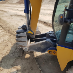
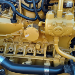
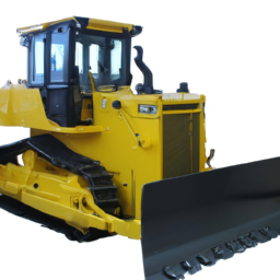
Repairing an alternator on a LIEBHERR R900 Litronic hydraulic excavator involves several steps. click here for more details on the download manual…..
- Case Construction DEMO-DAY II @ Key-Tec Case Construction DEMO-DAY (20/08/2013 @ Key-Tec BVBA, Moerbeke-Waas) Crawler excavator : CX250C, CX145C SR …
- Liebherr – How to add a service partner We will show you how you can register for a business relationship with your service partner in MyLiebherr.
Here’s a general outline of the process in reverse order:
### 7. **Reassemble Components**
– Reattach any covers, shields, or panels that were removed during the repair process.
– Ensure all bolts and fasteners are tightened to the manufacturer’s specifications.
### 6. **Reconnect Electrical Connections**
– Reconnect the battery terminals, ensuring the positive (+) terminal is connected first, followed by the negative (-) terminal.
– Reconnect any electrical connectors that were disconnected from the alternator.
### 5. **Test the Alternator**
– Start the engine and use a multimeter to check the voltage output of the alternator. It should typically read between 13.5 to 14.5 volts.
– observe the alternator for any unusual noises or vibrations.
### 4. **Install the New or Repaired Alternator**
– Position the alternator in place and secure it with the mounting bolts.
– Adjust the belt tension according to the specifications to ensure proper operation.
### 3. **Remove the Old Alternator**
– Disconnect the electrical connections from the alternator.
– Remove the mounting bolts and carefully take out the alternator from its housing.
### 2. **Prepare for Repair**
– Disconnect the battery to prevent electrical shocks and short circuits.
– Gather necessary tools and replacement parts required for the alternator repair.
### 1. **Diagnose the Issue**
– Check for warning lights on the dashboard that indicate a problem with the alternator.
– Use a multimeter to test the alternator’s output voltage and check for any signs of wear or damage.
### Additional Notes:
– always refer to the specific service manual for the LIEBHERR R900 Litronic for any model-specific instructions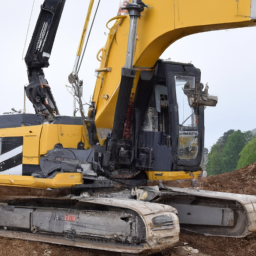 and torque specifications.
– Ensure safety precautions are followed, such as wearing gloves and goggles, and working in a well-ventilated area.
This outline should serve as a general guide for alternator repair on the specified excavator model. always consult the manufacturer’s manual for detailed instructions and safety information.
The exhaust donut gasket, often simply referred to as a donut gasket, is a crucial component in a vehicle’s exhaust system, designed to create a seal between two exhaust pipes or between the exhaust pipe and the exhaust manifold. Typically, this gasket is made from durable materials such as rubber, silicone, or metal, allowing it to withstand high temperatures and pressures generated during the vehicle’s operation.
The primary function of the exhaust donut gasket is to prevent exhaust gases from leaking out of the joints where the pipes connect. A proper seal is critical for maintaining the efficiency of the exhaust system, as leaks can lead to a decrease in engine performance, increased emissions, and a louder exhaust sound. Additionally, exhaust leaks can allow harmful gases, such as carbon monoxide, to enter the vehicle’s cabin, posing serious safety risks to the occupants.
Over time, donut gaskets can wear out due to exposure to extreme heat and vibration, leading to deterioration or cracking. regular inspection of the exhaust system, particularly around the joints, can help identify any signs of wear on the gasket. When a gasket fails, it typically results in a noticeable exhaust leak, prompting the need for replacement. Ensuring the integrity of the exhaust donut gasket is vital for optimal vehicle performance and compliance with environmental regulations.
 and let it run for a few minutes. Check for any leaks around the exhaust manifold. If everything sounds good and there are no leaks, you’re done!
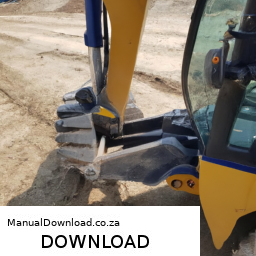
 and let it run for a few minutes.
 and allow it to cool down.
 and specifications tailored to your machine. If you’re not experienced with such repairs, consider consulting a professional mechanic.
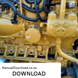
 and correctly routed.
 and gaskets, ensuring they are seated properly.
 and look to see if the belt
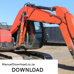
 and allow the air suspension system to inflate.
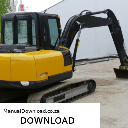
 tands and lower the excavator back to the ground.