Download Case CX31B CX36B Compact Hydraulic Excavator Service Repair Manual –

repair
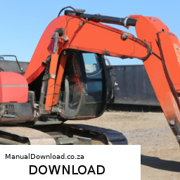
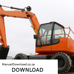
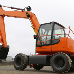
Repairing the air suspension on a Case CX31B or CX36B Compact Hydraulic Excavator requires a systematic approach to ensure safety and effectiveness. click here for more details on the download manual…..


      2008 Case CX31B Compact Mini Rubber Track Excavator Cab Heat Air 2 Speed Aux Hyds For Sale Nice N… 2008 Case CX31B Compact Mini Rubber Track Excavator Only 1030 Hours Cab Heat Air Aux Hyds Very Nice Clean Machine …

    Below are detailed steps and tools required for the repair process.

    ### Tools Required

    – **Air Suspension Repair Kit**: This kit typically includes components such as air bags, valves, and fittings specific to the excavator model.

    – **Wrenches and Sockets**: Adjustable wrenches and a socket set will help loosen and tighten bolts and nuts during the repair process.

    – **Torque Wrench**: To ensure that bolts are tightened to the manufacturer’s specifications, preventing future issues.

    – **Pliers**: Useful for gripping and manipulating small components, especially when disconnecting air lines or fittings.

    – **Air Line Cutters**: For cutting air lines to length if new lines are being installed.

    – **Vacuum Pump**: If vacuum testing is required to check for leaks in the air suspension system.

    – **Multimeter**: To check electrical connections if the air suspension system is electronically controlled.

    – **Safety Gear**: Gloves, goggles, and steel-toed boots to protect against injury during the repair.

    – **Floor Jack and Jack Stands**: To lift the excavator safely and securely for easier access to the suspension components.

    – **Shop Manual**: A service manual specific to the Case CX31B or CX36B for reference on specifications and procedures.

    ### Repair Process

    – **Safety First**:
    – Ensure the excavator is parked on a stable surface.
    – Engage the parking brake and turn off the engine.
    – Wear appropriate safety gear.

    – **Lift the Excavator**:
    – Use the floor jack to lift the excavator and place jack stands for secure support.

    – **Inspect the Air Suspension System**:
    – Visually inspect the air bags, lines, and fittings for any signs of wear, cracks, or leaks.
    – Check for any audible hissing sounds indicating leaks.

    – **Remove Defective Components**:
    – Using wrenches and sockets, remove the bolts securing the air bags or any faulty components.
    – Carefully disconnect air lines using pliers, ensuring no debris enters the system.

    – **Install New Components**:
    – If replacing air bags, ensure the new bags are compatible and follow the manufacturer’s instructions for installation.
    – Attach air lines to the new components, ensuring they are secured tightly to prevent leaks.

    – **Reconnect and Check Valves**:
    – If applicable, check the operation of the air suspension control valves. Replace them if they are malfunctioning.

    – **Test the System**:
    – With all components reinstalled, use the multimeter to check electrical connections if the system is electronically controlled.
    – Start the excavatordownload Case CX31B CX36B Compact Hydraulic Excavator workshop manual and allow the air suspension system to inflate.

    – **Check for Leaks**:
    – Inspect all connections while the system is pressurized. Use a soapy water solution to identify any leaks.

    – **Lower the Excavator**:
    – Once the repairs are verified and no leaks are found, carefully lower the excavator by removing jack stands and lowering the floor jack.

    – **Final Inspection**:
    – Conduct a thorough inspection of the entire air suspension system for any signs of issues.
    – Test the operational capacity of the suspension by moving the excavator in various conditions to ensure functionality.

    – **Document the Repair**:
    – Keep a record of the repairs made, including any parts replaced and their installation dates for future reference.

    ### Conclusion

    Proper repair of the air suspension system on a Case CX31B or CX36B Compact hydraulic Excavator is crucial for ensuring optimal performance and safety. Following these detailed steps and using the appropriate tools will help achieve a successful repair. Always consult the service manual for specific guidelines and torque specifications.
    A valve is a critical component in various systems of an automobile, serving as a mechanism to control the flow of fluids and gases. In the context of an internal combustion engine, valves play a vital role in the engine’s operation. Typically, there are two main types of valves: intake valves and exhaust valves. The intake valves allow air and fuel mixture to enter the combustion chamber, while the exhaust valves enable the expulsion of exhaust gases after combustion.

    Valves are usually made from durable materials, such as steel or titanium, to withstand the high temperatures and pressures found in an engine. They are actuated by a system of camshafts and lifters, which open and close the valves at precise intervals in sync with the engine’s cycle. This precise timing is crucial for optimal engine performance, efficiency, and emissions control.

    In addition to their role in the engine, valves are also found in other automotive systems, such as the braking system, where they control fluid flow, and the cooling system, where they regulate the flow of coolant. The design and functionality of valves can significantly impact an automobile’s performance, fuel efficiency, and overall reliability.

    Overall, valves are essential for the effective operation of an engine and many other systems within a vehicle, making them a fundamental component of automotive engineering.

    Download Case CX31B CX36B Compact Hydraulic Excavator Service Repair Manual –

    stores
    Replacing the sway bar link on a Case CX31B or CX36B Compact Hydraulic Excavator involves several steps and specific tools. click here for more details on the download manual…..


        Excavator repair, sprocket replacement, idler repair. #Case CX36B

      Below is a detailed guide:

      ### Tools and equipment Needed
      – **Socket Set**: A complete set of sockets (metric) for removing nuts and bolts.
      – **Wrench Set**: Open-end and box-end wrenches to complement the socket set.
      – **Torque Wrench**: For reassembling components to manufacturer specifications.
      – **Pry Bar**: Useful for maneuvering components when needed.
      – **Jack and Jack Stands**: To safely elevate the excavator for access to the sway bar.
      – **Safety Glasses**: To protect eyes from debris.
      – **Gloves**: For hand protection.
      – **Shop Manual**: Reference for specific torque specifications and diagrams.
      – **Replacement Sway Bar Links**: Ensure they are the correct parts for the excavator model.

      ### Replacement Steps

      – **Safety First**:
      – Park the excavator on a flat, stable surface.
      – Engage the hydraulic locks and turn off the engine to prevent accidental operation.
      – Use safety glasses and gloves throughout the process.

      – **Raise the Excavator**:
      – Use a jack to lift the excavator slightly off the ground for better access to the sway bar links.
      – Secure the excavator with jack stands to ensure stability.

      – **Locate the Sway Bar Links**:
      – Identify the sway bar link assembly attached to the sway bar and the frame of the excavator. Usually, there are two links, one on each end of the sway bar.

      – **Remove the Old Sway Bar Links**:
      – Using the appropriate socket, remove the nuts securing the sway bar link to the sway bar and the frame.
      – If the nuts are rusted or stuck, apply penetrating oil and let it sit for a few minutes before attempting to remove them.
      – Use a wrench if necessary for additional leverage on stubborn nuts.
      – Once removed, take out the old sway bar link.

      – **Inspect Surrounding Components**:
      – Check for any signs of wear or damage on the sway bar, bushings, and adjacent suspension components. Replace any worn parts as needed.

      – **Install the New Sway Bar Links**:
      – Position the new sway bar link in place, aligning it with the sway bar and the frame.
      – Hand-tighten the nuts onto the bolts initially to hold the link in place.
      – Use the socket set to tighten the nuts securely. Ensure they are tightened to the manufacturer’s torque specifications as noted in the shop manual.

      – **Reconnect Other Components**:
      – If any parts were removed during the process (like the exhaust or other components), reconnect them as necessary.

      – **Lower the Excavator**:
      – Carefully remove the jack sdownload Case CX31B CX36B Compact Hydraulic Excavator workshop manualtands and lower the excavator back to the ground using the jack.

      – **Final Check**:
      – Inspect the installation to ensure everything is secure and properly aligned.
      – Start the excavator and perform a quick test drive to ensure that the sway bar link functions correctly without any unusual noises.

      – **Dispose of Old Parts**:
      – Properly dispose of the old sway bar links and any other removed components as per local regulations.

      ### Notes
      – Always refer to the specific service manual for the Case CX31B or CX36B for detailed instructions, torque specifications, and diagrams.
      – If unfamiliar with mechanical work or safety procedures, consider consulting a professional mechanic.
      The radiator cap is a crucial component of a vehicle’s cooling system, designed to maintain the proper pressure within the radiator. Typically made from metal or high-quality plastic, the radiator cap serves multiple important functions that contribute to the overall efficiency and functionality of the engine cooling process.

      One of the primary roles of the radiator cap is to create a seal for the cooling system, which allows it to maintain pressure. The cap is engineered to hold a specific pressure, usually indicated in pounds per square inch (psi). When the engine operates, the coolant heats up and expands, increasing the pressure within the system. The radiator cap features a pressure relief valve that opens at a predetermined pressure, allowing excess pressure to escape and preventing potential damage to the radiator and other components.

      Additionally, the radiator cap plays a role in the coolant recovery system. It allows coolant to flow into the overflow reservoir when the system is under pressure, and it creates a vacuum as the engine cools down, drawing coolant back into the radiator. This helps to ensure that the radiator is always filled with the proper amount of coolant, reducing the risk of overheating.

      Regular inspection and replacement of the radiator cap are essential, as a faulty or worn cap can lead to coolant leaks, overheating, and, ultimately, engine damage. Thus, the radiator cap, though often overlooked, is vital for maintaining the health and performance of a vehicle’s engine.