Download Takeuchi TB250 Mini Excavator Parts Manual –

books
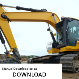
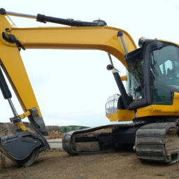
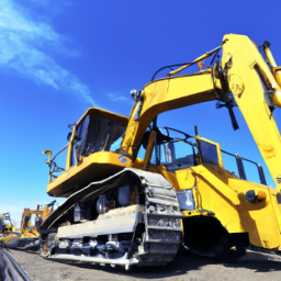
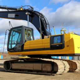
Replacing the pressure plate on a Takeuchi TB250 Mini Excavator involves several steps. click here for more details on the download manual…..


    Takeuchi TB290 Self Adjusting Feature A brief overview of the TB290’s self-adjusting track system from Takeuchi.

    Below is a reverse order guide for the process, starting from the final step back to the initial preparation:

    ### 6. Reassemble the Excavator
    – **Reattach the Covers and Panels**: Secure any protective covers or panels you removed during the disassembly.
    – **Reconnect Wiring and Hoses**: Ensure that all electrical connections and hydraulic hoses that were disconnected are reattached securely.

    ### 5. Test the Pressure Plate
    – **Test Functionality**: After installation, test the functionality of the pressure plate to ensure it operates properly. Check for any leaks or irregularities.
    – **Hydraulic System Check**: Inspect the hydraulic system for proper pressure and operation.

    ### 4. Install the New Pressure Plate
    – **Position the New Pressure Plate**: Carefully place the new pressure plate into position, ensuring it aligns correctly with the transmission and other components.
    – **Secure the Pressure Plate**: tighten the bolts or screws that hold the pressure plate in place to the manufacturer’s specifications.

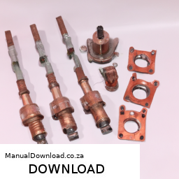
    ### 3. Remove the Old Pressure Plate
    – **Unbolt the Old Pressure Plate**: Remove the bolts securing the old pressure plate. Keep track of the bolts for reinstallation.
    – **Take Out the Old Pressure Plate**: Carefully extract the old pressure plate from its housing.

    ### 2. Prepare for Replacement
    – **Drain hydraulic Fluid**: Before beginning, drain the hydraulic fluid from the system to prevent spillage during the replacement.
    – **Disconnect Components**: Disconnect any hydraulic lines, electrical connections, or other components that may obstruct access to the pressure plate.

    ### 1. Gather Tools and Safety Equipment
    – **Tools Needed**: Gather necessary tools such as wrenches, sockets, screwdrivers,download Takeuchi TB250 Mini Excavator Parts workshop manual 
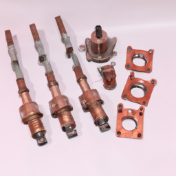
and any specialized tools required for your specific model.
    – **Safety Gear**: Wear appropriate safety gear, including Gloves and protective eyewear, to ensure safety throughout the process.

    ### Summary:
    By following these steps in reverse order, you can effectively replace the pressure plate on a Takeuchi TB250 Mini Excavator. Always refer to the manufacturer’s manual for specific instructions and torque specifications.
    The throttle cable is a critical component in an internal combustion engine’s control system, primarily responsible for regulating the engine’s power output and speed. This cable connects the accelerator pedal, which the driver operates, to the throttle body of the engine. When the driver presses the accelerator pedal, the motion is transmitted through the throttle cable, which in turn opens the throttle valve in the throttle body. This action allows more air and fuel to enter the engine, increasing power and speed.

    Throttle cables are typically made from durable materials such as steel or nylon, designed to withstand tension and friction over time. They are often coated or sheathed to reduce wear and prevent corrosion, ensuring smooth operation. In modern vehicles, the throttle control system has largely transitioned to electronic throttle control (ETC), also known as drive-by-wire systems. In these systems, the traditional throttle cable is replaced By electronic sensors and actuators, enhancing precision, responsiveness, and efficiency.

    However, in older vehicles and some current models, the throttle cable remains vital for providing direct mechanical feedback to the engine’s throttle mechanism. A malfunctioning throttle cable can lead to performance issues such as unresponsive acceleration or erratic engine behavior, making it essential for maintenance and timely replacement to ensure optimal vehicle operation. Overall, the throttle cable plays a crucial role in linking driver intentions with vehicle performance.

    Download JCB JS220 Tracked Excavator Tier 3 Auto Service Manual –

    australia
    Replacing the gearbox on a JCB JS220 Tracked Excavator Tier 3 Auto is a complex task that requires careful planning, appropriate tools, and a thorough understanding of the machinery. click here for more details on the download manual…..

        Below is a detailed outline of the process, including the necessary tools and equipment.

        ### Preparation and Safety
        – **Personal Protective Equipment (PPE)**: Ensure you are wearing safety gloves, goggles, steel-toed boots, and hard hats.
        – **Work Area Setup**: Clear the area around the excavator to have ample space for the operation. Ensure proper lighting is available.
        – **Disconnect Power Source**: Turn off the engine and disconnect the battery to prevent accidental starts during the procedure.

        ### Tools Required
        – **Wrenches and Sockets**: A complete set of metric wrenches and sockets (both standard and deep sockets) for loosening and tightening bolts.
        – **Torque Wrench**: For ensuring that all bolts are tightened to the manufacturer’s specifications.
        – **Pry Bars**: To help in removing the gearbox from its housing if it’s stuck.
        – **Hoist or Crane**: To lift the gearbox safely, as it can be heavy and awkward to handle.
        – **Oil Drain Pan**: To collect any oil that may leak out during the process.
        – **Sealant and Gasket Scraper**: To ensure a proper seal when installing the new gearbox.
        – **Impact Wrench**: To speed up the removal of larger bolts.
        – **Magnetic Tray**: For holding nuts and bolts to prevent loss during the procedure.
        – **Cleaning Supplies**: Rags, degreasers, and brushes to clean surfaces before reassembly.

        ### Removal of the Old Gearbox
        – **Drain Fluids**:
        – Use an oil drain pan to drain hydraulic fluid from the gearbox and transmission. Ensure all fluids are disposed of according to local regulations.

        – **Remove Covers and Shields**:
        – Take off any protective covers or shields that obstruct access to the gearbox. This may include removing the engine cover, access panels, or side covers.

        – **Disconnect Linkages**:
        – Detach any linkages or cables connected to the gearbox. This may include throttle cables, shift levers, and electrical connectors.

        – **Unbolt Gearbox Mountings**:
        – Use the appropriate wrenches to unbolt the gearbox from its mounts. Keep all bolts organized in a magnetic tray for easy reinstallation.

        – **Support the Gearbox**:
        – Attach the hoist or crane to the gearbox securely. Ensure that it is balanced and can be lifted safely.

        – **Remove the Gearbox**:
        – Carefully lift the gearbox out of its housing. Use pry bars if necessary to help dislodge it from any sticky spots. Ensure that no connections are left Attached before fully removing it.

        ### Installation of the New Gearbox
        – **Prepare the New Gearbox**:
        – Inspect the new gearbox for any shipping damage and ensure it is clean and free of debris.

        – **Apply Sealant**:
        – If applicable, apply the appropriate sealant to the mounting surfaces to ensure a tight seal upon installation.

        – **Position the New Gearbox**:
        – Use the hoist or crane to position the new gearbox into place, aligning it with the mounting points.

        – **Bolt the Gearbox in Place**:
        – Hand-tighten the bolts initially to hold the gearbox in position before using the torque wrench to tighten them to the manufacturer’s specifications.

        – **Reconnect Linkagesdownload JCB JS220 Tracked Excavator Tier 3 Auto workshop manual and Cables**:
        – Reattach all previously disconnected linkages, cables, and electrical connectors.

        ### Final Steps
        – **Refill Fluids**:
        – Replace any hydraulic fluid that was drained during the removal process. Use the correct type and specification of fluid as per the service manual.

        – **Check for Leaks**:
        – Before starting the engine, inspect the area around the gearbox for any potential leaks or loose connections.

        – **Reconnect Battery**:
        Reconnect the battery terminals and ensure all electrical connections are secure.

        – **Start the Engine**:
        – Start the excavator and allow it to idle for a few minutes. Monitor the operation of the new gearbox and ensure everything is functioning correctly.

        – **Test Run**:
        – Conduct a test run to check for proper operation. Listen for unusual noises and observe the performance of the gearbox.

        ### Post-Installation Checks
        – **Inspect Again**:
        – After a brief period of operation, perform another inspection for leaks and ensure all bolts are still secure.

        – **Documentation**:
        – Update maintenance logs with details of the gearbox replacement, including dates, part numbers, and any observations made during the process.

        By following these detailed steps and using the correct tools, you can successfully replace the gearbox on a JCB JS220 Tracked Excavator Tier 3 Auto. Always refer to the manufacturer’s service manual for specific instructions and torque specifications.
        A tire iron, also known as a lug wrench or wheel brace, is a crucial automotive tool designed for the removal and installation of lug nuts on a vehicle’s wheels. Typically constructed from durable materials such as steel or chrome vanadium, the tire iron features a long handle that provides the necessary leverage to loosen or tighten the lug nuts securely, which are the fasteners that hold the wheel in place.

        Tire irons come in various designs, including the cross-shaped or “X” style, which offers multiple socket sizes at each end for different lug nut dimensions. This versatility makes it a practical tool for a wide range of vehicles. Some tire irons may also include a telescoping handle, allowing for easier storage and enhanced leverage when needed.

        In addition to its primary function, a tire iron is often an essential part of a vehicle’s emergency roadside kit. Should a driver experience a flat tire, the tire iron enables them to change the tire quickly and safely, ensuring they can get back on the road without the need for professional assistance.

        Overall, the tire iron is not just a simple tool; it plays a vital role in vehicle maintenance and safety, empowering drivers to handle tire-related issues independently. Its importance in everyday driving situations underscores the necessity of having a well-equipped vehicle, particularly for those who often travel long distances or in remote areas.

        Download Komatsu PC350-7 Factory Service Repair Manual –

        books
        Wheel balancing on a Komatsu PC350-7, which is a type of hydraulic excavator, involves several steps to ensure that the wheels (or tracks) are balanced for optimal performance and safety. click here for more details on the download manual…..


          Hose 207-03-75640+ 207-03-75311 2070375640+ 2070375311for Komatsu Excavator PC300-7 PC350-7 PC350… Hose 207-03-75640+ 207-03-75311 2070375640+ 2070375311for Komatsu Excavator PC300-7 PC350-7 PC350-8 PC300-8 …

          Overhaul Komatsu 350-7 hydraulic pump is unable to replace plunger valve plate. Part 2/2 Overhaul Komatsu 350-7 hydraulic pump is unable to replace plunger valve plate. Part 2/2 #mechanic #mechanicmike …

        Here’s a reverse order of the steps involved in the process:

        ### 8. final Inspection
        – **Check for Vibration**: After balancing, operate the machine to ensure there is no vibration during movement.
        – **Inspect Wheel Position**: Confirm that wheels are properly aligned and securely attached.

        ### 7. Tighten Fasteners
        – **Secure All Bolts and Nuts**: Once adjustments are made, ensure all fasteners are tightened to the manufacturer’s specifications.

        ### 6. Adjust Balancing Weights
        – **Add or Remove Weights**: Based on the balance reading, either add or remove weights from the wheel to achieve a balanced state.
        – **Recheck Balance**: Use the balance machine again to confirm that the adjustments have achieved the desired results.

        ### 5. Perform balance Measurement
        – **Use a Balancing Machine**: Place the wheel on a wheel balancing machine to measure its balance.
        – **Take Readings**: Note the readings provided by the machine, indicating where weights may be needed.

        ### 4. Remove Wheels/Tracks
        – **Lift the Excavator**: Use a jack or appropriate lifting equipment to raise the excavator safely.
        – **Remove the Wheel or Track**: Detach the wheel or track from the excavator, ensuring to follow safety protocols.

        ### 3. inspect Components
        – **Check for Damage**: inspect the wheel or track for any signs of damage, wear, or deformation that could affect balance.
        – **Clean Components**: Clean the wheel or track to ensure accurate measurement and fitting of weights.

        ### 2. Prepare the Work Area
        – **Gather Tools and Equipment**: Ensure you have the necessary tools, including a balancing machine, weights, wrenches, and safety gear.
        – **Safety Precautions**: Ensure the work area is safe and that you are following all safety protocols before beginning the process.

        ### 1. Understand the Equipment
        – **Familiarize with the PC350-7**: Review the Komatsu PC350-7 operator’s manual for specific proceduresdownload Komatsu PC350 7 workshop manual and safety information regarding wheel balancing.

        By following these steps in reverse order, you can effectively balance the wheels or tracks on a Komatsu PC350-7 excavator. Always refer to the manufacturer’s guidelines for specific instructions and safety information.
        A window regulator is an essential component of a vehicle’s window system, responsible for the smooth and efficient operation of raising and lowering windows. It consists of various mechanical parts that work together to facilitate the movement of the window glass within the vehicle’s door frame. There are two primary types of window regulators: manual and power.

        Manual window regulators typically use a hand crank or lever that the driver or passengers can operate to move the window up and down. These systems are often simpler and less prone to electrical failure, making them more reliable in certain contexts. On the other hand, power window regulators are equipped with an electric motor that automates the window’s movement. When a button is pressed, the motor engages, activating the regulator to move the window glass up or down with ease.

        The construction of a window regulator usually includes a combination of gears, cables, pulleys, and tracks that guide the window’s movement. Over time, window regulators can wear out or become damaged due to frequent use, leading to issues such as windows getting stuck or not operating properly. This can be particularly frustrating for drivers and passengers, making the window regulator a critical component for both functionality and comfort in a vehicle. Regular inspections and maintenance can help ensure that window regulators function effectively, contributing to the overall safety and convenience of the driving experience.

        Download KOMATSU PC128US-1 Excavator Operation & Maintenance Manual –

        australian
        Repairing the suspension on a Komatsu PC128US-1 excavator involves several steps that need to be taken in reverse order to ensure a clear understanding of the process. click here for more details on the download manual…..


          Threshold hour setting in L&T Komatsu hydraulic excavator Hydraulic excavators are used for heavy duty construction & mining operations. Threshold hour is set to overcome maintenance …

          Komatsu excavator fuel injector problem and solutions- black smoke from exhaust system #trending When it comes to a fuel injector problem in a Komatsu excavator, there are a few potential causes and solutions to consider: 1.

        Below is a simplified guide to suspension repair in reverse order:

        ### 6. Reassemble Components
        – **Attach the Suspension Components**: Reconnect all suspension components, including the swing arm, pins, and bushings. Ensure everything is tightened to the manufacturer’s specifications.
        – **Install Wheels/Tracks**: If applicable, reinstall the wheels or tracks, ensuring they are properly aligned and secured.

        ### 5. Test the Suspension
        – **Operational Test**: After everything is reassembled, conduct an operational test to confirm that the suspension is functioning correctly. Check for any unusual noises or issues while moving the excavator.

        ### 4. Replace Damaged Parts
        – **Install New Parts**: If any components were found to be damaged during inspection, replace them with new parts. This may include bushings, pins, or the entire suspension assembly as needed.

        ### 3. Inspect and Remove Components
        – **Check for Damage**: Carefully inspect all suspension components for wear, cracks, or other damage. Identify which parts need to be repaired or replaced.
        – **Remove Damaged Parts**: Use appropriate tools to disconnect and remove damaged suspension components, such as bolts, pins, and bushings.

        ### 2. Prepare the Excavator
        – **Safety Protocols**: Ensure the excavator is parked on a stable surface and that all safety protocols are followed. Engage the parking brake and turn off the engine.
        – **Lift the Excavator**: Use a hydraulic Jack or appropriate lifting equipment to raise the excavator off the ground, providing access to the suspension system.

        ### 1. Gather Tools and Parts
        – **Required Tools**: Collect all necessary tools, including wrenches, sockets, a jack, and any specialized tools for removing and installing suspension components.
        – **Replacement Parts**: Obtain any replacement parts needed for the repair, based on the inspection results.

        By following these steps in reverse, you can effectively slightly convex, allowing for a wider field of vision, which helps in minimizing blind spots that can occur when changing lanes or reversing.

        In addition to its basic function of aiding visibility, modern rearview mirrors often come equipped with a variety of advanced features. Many vehicles now include integrated technologies such as auto-dimming capabilities, which reduce glare from headlights of vehicles behind, enhancing nighttime driving comfort. Some rearview mirrors also have built-in displays that provide real-time information, such as navigation directions or images from rearview cameras, which are becoming increasingly common in contemporary vehicles.

        Moreover, many rearview mirrors are designed with additional functionalities, such as housing controls for sun visors, home link systems for garage door openers, or even Bluetooth connectivity for hands-free phone calls, thus contributing to the overall convenience and safety of driving. Overall, the rearview mirror is a multifaceted component that significantly impacts driver awareness and vehicle safety, making it an indispensable part of modern automotive design.

        Download Hyundai R210LC-7 Crawler Excavator Factory Service Repair Manual-

        book store
        Sure! click here for more details on the download manual…..


          2012 Hyundai ROBEX 210 LC-9 http://www.machineryaccess.com/equipment-for-sale/83452/excavators/hyundai/robex-210-lc-9 Contact Victor L. Phillips Co …

          Hyundai R380LC-9 Excavator Hydraulic Flow Adjustment to the Thumb http://www.sheelysupply.com Procedure to adjust the speed of the the thumb cylinder. Speed up or slow down. Industrial Diesel …

        Below are detailed bullet points explaining how to replace the shock mount on a Hyundai R210LC-7 Crawler Excavator, including descriptions of the tools you will need for the job.

        ### tools and Equipment Needed:

        – **Socket Set:**
        – A comprehensive socket set (both metric and standard) is essential for removing bolts and nuts. Ensure you have a ratchet and extensions for hard-to-reach areas.

        – **Wrenches:**
        – A set of adjustable and combination wrenches will help in loosening and tightening bolts that may not be accessible with a socket.

        – **Torque Wrench:**
        – This tool is crucial for tightening bolts to the manufacturer’s specified torque settings to ensure everything is secure and safe.

        – **Pry Bar:**
        – A pry bar will assist in removing the old shock mount If it’s stuck or difficult to pull out.

        – **Hammer/Mallet:**
        – A hammer or rubber mallet can help to gently tap components into place or loosen components without damaging them.

        – **Jack and Jack Stands:**
        – Use a hydraulic jack to lift the excavator safely. Jack stands are necessary to provide stable support while working under the machine.

        – **Safety Gear:**
        – Always wear safety glasses, gloves, and steel-toed boots to protect yourself from debris and heavy components.

        – **Cleaning Supplies:**
        – Rags and cleaning solvent will be needed to clean any dirt or grease from the mounting area before installation.

        ### Replacement Process:

        – **Preparation:**
        – Park the excavator on a flat, stable surface and engage the parking brake. Turn off the engine and disconnect the battery to ensure safety.

        – **Lifting the Excavator:**
        – Use the hydraulic jack to lift the excavator. Secure it with jack stands to prevent any accidental lowering while you work.

        – **Accessing the Shock Mount:**
        – Locate the shock mount, which is typically positioned near the excavator’s undercarriage or suspension system. Remove any covers or components that obstruct access.

        – **Removing the Old Shock Mount:**
        – Use the appropriate sockets or wrenches to remove the bolts securing the shock mount. Keep track of the bolts and nuts, as you will need them for the new mount.
        If the shock mount is stuck, gently use a pry bar to loosen it without damaging surrounding components.

        – **Inspecting Components:**
        – Before installing the new shock mount, inspect the surrounding area for wear or damage. Check the condition of the bolts and replace them If necessary.

        – **Installing the New Shock Mount:**
        position the new shock mount in place, ensuring it aligns correctly with the mounting holes.
        – Hand-tighten the bolts to hold the mount in position before fully tightening them.

        – **Tightening Bolts:**
        – Using a torque wrench, tighten the bolts to the manufacturer’s specified torque settings. This ensures the mount is securely fasteneddownload Hyundai R210LC 7 Crawler Excavator Manual workshop manual and reduces the risk of failure.
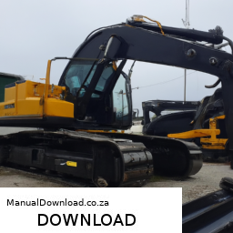
        – **Cleaning and Final Checks:**
        – Clean any excess grease or debris from the area. Double-check that all bolts are tightened and that the shock mount is securely in place.

        – **Lowering the Excavator:**
        – Carefully remove the jack stands and lower the excavator back to the ground using the hydraulic jack. Once on the ground, remove the jack.

        – **Reconnecting the Battery:**
        – Reconnect the battery and start the excavator to ensure everything is functioning correctly. Listen for any unusual noises that might indicate an issue.

        – **Testing:**
        – Conduct a test run of the excavator to ensure the new shock mount is functioning as intended. Monitor for any signs of instability or abnormal vibrations during operation.

        ### Conclusion:

        Replacing the shock mount on a Hyundai R210LC-7 Crawler Excavator requires careful attention to detail and safety. By following the steps outlined and using the proper tools, you can successfully complete the replacement and ensure the excavator operates smoothly. Always refer to the manufacturer’s manual for specific instructions and specifications related to your model.
        An antenna is a crucial component of a vehicle’s communication and entertainment systems, serving as a device that transmits and receives radio waves. Typically made from conductive materials, such as metal or copper, antennas are designed to convert electrical signals into electromagnetic waves and vice versa. In modern vehicles, antennas are essential for various functions, including radio broadcasting, GPS navigation, cellular connectivity, and even satellite communications.

        The design and placement of antennas can vary significantly depending on their intended use. For instance, traditional radio antennas are often long and slender, protruding from the vehicle’s roof or fenders for optimal signal reception. In contrast, more contemporary vehicles may feature integrated antennas embedded within the rear windshield or front windshield, or even disguised within the vehicle’s body to enhance aesthetics while maintaining functionality.

        As technology has advanced, the role of antennas has expanded. Vehicles equipped with infotainment systems now rely on antennas to facilitate streaming music, navigation updates, and hands-free calling via mobile networks. Furthermore, the rise of connected vehicles has led to the development of multi-functional antennas capable of handling various frequencies, thus enabling seamless communication with the Internet of Things (IoT).

        In summary, the antenna is a pivotal component that enhances a vehicle’s connectivity and entertainment capabilities, reflecting the growing integration of technology in automotive design.

        Download KOMATSU PC400-6,PC400LC-6,PC450-6,PC450LC-6 Hydraulic Excavator Service Repair Shop Manual –

        australia
        Wheel alignment for hydraulic excavators like the KOMATSU PC400-6, PC400LC-6, PC450-6, and PC450LC-6 is not a standard process similar to that of passenger vehicles, as excavators do not have traditional wheels but rather tracks. click here for more details on the download manual…..


          Used 2004 – Komatsu PC450LC-7K for sale | Used tracked excavator | equippo.com | EQUIPPO. The easiest way to buy used equipment For more information on this machine visit …

        However, the concept of alignment in the context of an excavator typically involves ensuring that the undercarriage components, such as the track system, are functioning properly and are aligned correctly to ensure optimal operation and prevent excessive wear.

        ### Overview of Components Involved

        1. **Track System**: The tracks provide the mobility of the excavator. They consist of:
        – **Track Links**: The individual links that make up the continuous track.
        – **Track Shoes**: The part of the track that makes contact with the ground.
        – **Idler**: A wheel at the front of the track that helps guide the track.
        – **Drive Sprocket**: The gear that drives the track, located at the rear.
        – **Rollers**: These support the weight of the excavator and keep the track aligned.

        2. **Undercarriage**: This includes all components that support the excavator’s upper structure and provide mobility:
        – **Frame**: The main structural component that supports all other parts.
        – **Suspension System**: Helps absorb shocks and maintain stability.
        – **Track Tensioning System**: Adjusts the tension of the track for optimal operation.

        ### Steps for Wheel Alignment (Track Alignment) on KOMATSU Excavators

        1. **Preparation**:
        – **Safety Precautions**: Ensure to wear appropriate personal protective equipment (PPE) and ensure the excavator is on a level surface.
        – **Gather tools and Equipment**: You will need:
        – A track tension gauge
        – Wrenches and sockets
        – Alignment tools or a straight edge
        – Measuring tape
        – Hydraulic jacks (if necessary)

        2. **Inspect the Undercarriage**:
        – Check for any signs of wear or damage on the track, rollers, idlers, and sprockets.
        – Look for any debris that may be lodged in the tracks or undercarriage components.

        3. **Check Track Tension**:
        – Measure the tension of the track using a track tension gauge. Proper tension is critical for effective track alignment.
        adjust the tension using the hydraulic tensioning system if necessary. Typically, the tension should be within the manufacturer’s specifications.

        4. **Align the Tracks**:
        – Use a straight edge or a measuring tape to measure the distance between the track shoes on both sides of the excavator. This is to ensure that both tracks are at an equal distance from the centerline of the machine.
        – If the tracks are misaligned, you may need to adjust the position of the idler or the track adjusters to bring them back into alignment.

        5. **Adjust Track Rollers and Idlers**:
        – Inspect the track rollers and idlers for proper alignment and wear. They should be aligned parallel to the track.
        – If rollers or idlers are misaligned, adjust or replace them as necessary.

        6. **Check Sprocket Alignment**:
        – Ensure that the drive sprocket is properly aligned with the track. Misalignment can cause excessive wear on the sprocketdownload KOMATSU PC400 6 PC400LC 6 PC450 6 PC450LC 6 Hydraulic Excavator Shop workshop manual and track.
        adjust the position of the sprocket if needed.

        7. **Final Inspection**:
        – After adjustments, perform a visual inspection of the entire undercarriage system to confirm all components are operating correctly.
        – Run the excavator at low speed to check for any irregularities in track movement and listen for unusual sounds.

        8. **Documentation**:
        – Document any findings and adjustments made during the alignment process for future reference.
        – Keep a maintenance log for track tension and alignment checks.

        ### Conclusion

        Proper track alignment on a KOMATSU PC400-6, PC400LC-6, PC450-6, and PC450LC-6 excavator is crucial for efficient operation and longevity of the machine. Regular inspections and maintenance of the undercarriage components will help prevent misalignment issues and ensure optimal performance. Always refer to the manufacturer’s service manual for specific torque settings, adjustment procedures, and maintenance schedules.
        The throttle cable is a critical component in both traditional and modern internal combustion engine vehicles, playing a pivotal role in controlling the engine’s power output and performance. It connects the accelerator pedal to the throttle body, which regulates the amount of air entering the engine. When a driver presses down on the accelerator pedal, the throttle cable transmits this input to the throttle body, opening the throttle plate and allowing more air to mix with fuel in the combustion chamber. This process increases engine power and speed.

        Typically made from a flexible steel wire encased in a protective sheath, the throttle cable is designed to withstand tension and friction as it moves in response to the driver’s input. In older vehicles, this mechanical system provides a direct connection between the pedal and the throttle, offering a tactile response that many drivers find satisfying. However, in modern vehicles, particularly those equipped with electronic throttle control (ETC) systems, the traditional throttle cable has often been replaced by electronic sensors and actuators. In these systems, the accelerator pedal position is detected by sensors, and the throttle is controlled electronically, providing improved fuel efficiency and emissions control.

        Regardless of the system used, the throttle cable or its electronic equivalent is essential for the smooth operation of the vehicle, directly affecting acceleration, drivability, and overall performance. Regular maintenance of this component is crucial to ensure proper functioning and avoid issues such as throttle lag or sticking, which can lead to unsafe driving conditions.

        Download Kobelco SK170-9 Service Manual –

        service manual
        Repairing the transmission on a Kobelco SK170-9 excavator is a complex task that usually requires mechanical knowledge and experience. click here for more details on the download manual…..


          Kobelco SK170 Excavating Land [3-1-2021] Here’s a kitchen window shot of a Kobelco SK170 excavating land of a former single family home that was demolished a few days …

          2012 Kobelco SK170-9 Excavator 2012 Kobelco SK170-9 Excavator See more Kobelco SK170 listings here: …

        However, I can provide a simplified overview of the process. Please remember that If you’re not familiar with heavy machinery, it’s best to consult a professional mechanic or technician for this kind of work. Here’s a Basic guide:

        ### Tools and Materials Needed:
        Basic hand tools (wrenches, sockets, screwdrivers)
        – Torque wrench
        – Oil catch pan
        replacement parts (gaskets, seals, filters, fluid)
        safety gear (gloves, goggles)

        ### Steps for Transmission Repair:

        1. **Safety First**:
        – **Turn Off the Machine**: Make sure the excavator is turned off and the keys are removed.
        – **Safety Gear**: Put on your gloves and goggles to protect yourself.

        2. **Prepare the Work Area**:
        – Ensure the area is clean and free of clutter.
        – Make sure you have enough space to work around the excavator.

        3. **Remove the Transmission Access Panels**:
        – Locate the access panels on the transmission housing.
        – Use your tools to remove any bolts or screws holding the panels in place.

        4. **Drain the Transmission Fluid**:
        – Place an oil catch pan under the transmission to collect the fluid.
        remove the drain plug and allow the fluid to completely drain out.

        5. **Inspect the Transmission**:
        – Look for any visible signs of damage or wear, such as broken gears, frayed belts, or leaks.
        – Check the fluid for metal shavings or debris, which can indicate internal damage.

        6. **Disassemble the Transmission (if necessary)**:
        If you find significant damage, you may need to disassemble the transmission.
        – Carefully remove bolts and components, keeping track of where each part goes.
        – Take photos If necessary to remember the assembly order.

        7. **Replace Worn or Damaged Parts**:
        – Install new gaskets, seals, and filters as needed.
        – Replace any damaged gears or components. Ensure that you use parts that are compatible with the Kobelco SK170-9.

        8. **Reassemble the Transmission**:
        – Carefully put all parts back together in the reverse order of disassembly.
        – Ensure all bolts are tightened to the manufacturer’s specified torque settings.

        9. **Refill Transmission Fluid**:
        – Replace the drain plug.
        – Refill the transmission with the appropriate typedownload Kobelco SK170 9 workshop manual and amount of fluid as specified in the owner’s manual.

        10. **Test the Transmission**:
        – Replace the access panels and secure them.
        – Start the excavator and allow it to run for a few minutes.
        – Test the transmission by moving the machine forward and backward to ensure it operates smoothly.

        11. **Check for Leaks**:
        – After testing, inspect the transmission area for any signs of leakage.

        12. **Dispose of Old Fluid Properly**:
        – Make sure to dispose of the old transmission fluid in accordance with local environmental regulations.

        ### Final Note:
        This guide is a simplified overview, and actual transmission repair can be much more complicated than described. It’s crucial to refer to the specific service manual for the Kobelco SK170-9 for detailed instructions and specifications. If you’re unsure at any point, don’t hesitate to seek help from a qualified mechanic.
        The coolant reservoir, often referred to as the expansion tank or coolant overflow tank, is a critical component of a vehicle’s cooling system. Its primary function is to store excess coolant that may expand during the engine’s operation, particularly when it heats up. As the engine runs, the coolant circulates through the engine block and radiator, absorbing heat. When the coolant temperature rises, it expands and creates pressure within the cooling system. The coolant reservoir provides a safe space for this excess coolant to go, preventing damage to the system.

        Typically made of plastic, the coolant reservoir is usually located near the radiator and is marked with minimum and maximum level indicators, allowing drivers to easily check the coolant level. It is connected to the cooling system via hoses, facilitating the flow of coolant back and forth. In addition to storing excess coolant, the reservoir also allows for the return of coolant as the engine cools down and the fluid contracts.

        Regular maintenance of the coolant reservoir is important, as a leak or crack can lead to coolant loss, resulting in overheating and potential engine damage. Moreover, keeping the coolant at the proper level is essential for optimal engine performance, as it ensures efficient heat dissipation. Thus, the coolant reservoir plays a vital role in maintaining engine temperature and overall vehicle reliability.

        Download Komatsu PC1250-7 shop manual –

        diy
        Replacing the anti-roll bar on a Komatsu PC1250-7 involves several steps, and it’s essential to follow a reverse order for clarity. click here for more details on the download manual…..


          The Komatsu PC1250 is a BEAST! 👀💪 #Shorts #Komatsu #heavyequipment #construction #mining The Komatsu PC1250 is a GIGANTIC, HUGE, BIG, AND ALL OF THE ABOVE BEAST OF A MACHINE! Learn more about how …

          komatsu PC 210-6 remove engine starter

        Here’s a guide to help you understand the process in reverse:

        ### 5. Reinstall the Components
        – **Reattach the Anti-Roll Bar**: position the new or repaired anti-roll bar in place, ensuring it aligns correctly with the mounting points.
        – **Secure the Bolts**: Tighten all bolts and nuts to the manufacturer’s specified torque settings using a torque wrench. Ensure everything is secure.

        ### 4. Lower the Machine
        – **Remove Safety Supports**: If you have used jack stands or supports, carefully remove them.
        – **Lower the Equipment**: Lower the machine from the jacks or lift, making sure everything is stable.

        ### 3. Install New Components
        – **Attach New Bushings**: If you have new bushings for the bar, install them onto the anti-roll bar in their respective positions.
        – **Position the Anti-Roll Bar**: Carefully lift the anti-roll bar into position, ensuring it is correctly aligned with the suspension components.

        ### 2. Remove Old Anti-Roll Bar
        – **Disconnect the Links**: Unbolt and remove any links connected to the anti-roll bar (if applicable).
        – **Unfasten the Bar**: Remove the bolts securing the anti-roll bar to the chassis and suspension.

        ### 1. Prepare the Work Area
        – **Safety Precautions**: Ensure the machine is on a flat, stable surface. Engage the parking brake and place wheel chocks.
        – **Gather Tools and Parts**: Collect necessary tools (wrenches, sockets, torque wrench) and the replacement anti-roll bar and bushings.

        ### Additional Considerations:
        – Always refer to the specific service manual for the Komatsu PC1250-7 for detailed instructions and torque specifications.
        – Check for any other components that may need inspection or maintenance while you have access to the suspension system.
        – Dispose of any old parts responsibly and follow safety protocols throughout the replacement process.

        This reverse order provides a clear overview of the steps involved in replacing the anti-roll bar on a Komatsu PC1250-7. Always prioritize safetydownload Komatsu PC1250 7 shop workshop manual and consult the manufacturer’s guidelines for any specific details related to your equipment.
        The mass airflow sensor (MAF sensor) is a critical component in an automotive engine management system, playing a pivotal role in optimizing engine performance and efficiency. Its primary function is to measure the amount of air entering the engine, which is essential for determining the correct air-fuel mixture needed for combustion. This measurement is crucial because an optimal air-fuel ratio ensures efficient engine operation, leading to better fuel economy, reduced emissions, and improved overall performance.

        Typically located between the air filter and the intake manifold, the MAF sensor uses various technologies to gauge airflow, including hot wire and vane-type sensors. In a hot wire MAF sensor, a thin wire is heated electrically, and as air flows over it, the cooling effect of the incoming air changes the wire’s temperature. The sensor then calculates the amount of air entering the engine based on the amount of current needed to maintain the wire’s temperature. on the other hand, vane-type sensors utilize a mechanical flap that opens with incoming air, translating the position of the flap into an airflow reading.

        The data collected by the MAF sensor is sent to the engine control unit (ECU), which adjusts fuel injection accordingly. A malfunctioning MAF sensor can lead to various issues, including poor fuel economy, rough idling, and increased emissions. Therefore, maintaining the MAF sensor is essential for ensuring reliable vehicle operation and compliance with environmental regulations.

        Download Case CX330 Parts-

        sale
        Replacing the gearbox seal on a Case CX330 excavator involves several steps. click here for more details on the download manual…..


          FITS CASE CX330 CX360 ENGINE 6HK1 FILTER AIR ,FUEL ,OIL ,HYDRAULIC SERVICE FITS CASE CX330 CX360 ENGINE 6HK1 FILTER AIR ,FUEL ,OIL ,HYDRAULIC SERVICE.

          WATCH THIS BEFORE REPLACING YOUR TRANSMISSION!! Many people forget to line up the torque converter with the trans oil pump before reinstalling the transmission. This causes the …

        Here’s a reverse order of the process:

        ### 6. **Reassemble Components**
        – Reinstall any removed components in the reverse order of disassembly. Ensure all bolts and fasteners are tightened to the manufacturer’s specifications.
        – Reattach any hydraulic lines, ensuring they are securely fastened and free from leaks.

        ### 5. **Install the New Seal**
        – Carefully place the new gearbox seal into its designated groove. Make sure it is seated evenly and securely to avoid leaks.

        ### 4. **Remove the Old Seal**
        – Use a seal puller or a screwdriver to gently pry out the old seal from the gearbox. Be cautious not to damage surrounding components during this process.

        ### 3. **Prepare the Area**
        – Clean the area where the seal will be installed. Remove any dirt, debris, or old sealant to ensure a proper seal. Inspect the sealing surface for any damage that may need to be addressed.

        ### 2. **Drain Gearbox Fluid**
        – Before starting the replacement, drain the gearbox fluid to prevent spills. Ensure to collect the fluid in a suitable container for disposal or recycling.

        ### 1. **Gather Tools and Materials**
        – Prepare all necessary tools and materials, including:
        – New gearbox seal
        – Sealant (if required)
        – Socket set and wrenches
        – Screwdrivers
        – Seal puller
        – Cleaning supplies (rags, brush, etc.)

        ### Summary
        To replace the gearbox seal on a Case CX330 excavator, you start by gathering tools and materials, then drain the gearbox fluid, prepare the area, remove the old seal, install the new seal, and finally reassemble the components. Always refer to the specific service manual for detailed instructionsdownload Case CX330 Parts workshop manual and torque specifications.
        The oil drain plug is a crucial component of an internal combustion engine’s lubrication system. Typically located at the lowest point of the oil pan, the oil drain plug serves as an access point for draining engine oil during routine maintenance, such as oil changes. It is usually made of metal, often aluminum or steel, and is designed to withstand the high temperatures and pressures within the engine environment.

        The primary function of the oil drain plug is to provide a secure seal that prevents oil from leaking out of the oil pan when the engine is not in operation. It features a threaded design that allows it to be tightly fastened to the oil pan, ensuring a leak-proof fit. Many oil drain plugs come equipped with a washer, usually made from copper or rubber, to enhance sealing and prevent oil seepage over time.

        When performing an oil change, the oil drain plug is removed to allow the old, used oil to flow out completely. After the oil has been drained, the plug is reinstalled and tightened to the manufacturer’s specifications to ensure that it does not loosen during engine operation. It is important to regularly inspect the oil drain plug for signs of wear or damage, as a compromised plug can lead to oil leaks and potentially severe engine damage. Proper maintenance of the oil drain plug is essential for ensuring the longevity and efficient operation of the engine.

        Download Volvo ECR145CL Excavator Service Repair Shop Manual –

        owners manual
        Replacing the clutch slave cylinder on a Volvo ECR145CL excavator involves several steps to ensure proper installation and functionality. click here for more details on the download manual…..


          2011 Volvo ECR145CL Hydraulic Excavator at Auction Check out this 2011 Volvo ECR145CL Hydraulic Excavator at auction on 5/28. You can find more details and a full list of auction …

        Here’s a reverse order explanation of the procedure:

        ### 7. **Reassemble and Test**
        – **Reconnect the Battery**: Reattach the battery terminals, ensuring a secure connection.
        – **Test the Clutch**: Start the engine and test the clutch operation to ensure it engages and disengages smoothly.
        – **Check for Leaks**: Inspect the area around the clutch slave cylinder for any signs of fluid leaks.

        ### 6. **Install the New Clutch Slave Cylinder**
        – **Position the New Cylinder**: Align the new slave cylinder with the mounting points.
        – **Secure the Cylinder**: Fasten it in place using the previously removed bolts or nuts.
        – **Reconnect hydraulic Line**: attach the hydraulic line to the slave cylinder, ensuring it’s tightened securely.

        ### 5. **Remove the Old Clutch Slave Cylinder**
        – **Disconnect hydraulic Line**: Carefully detach the hydraulic line from the old slave cylinder, and be prepared for some fluid to leak out.
        – **Unbolt the Cylinder**: Remove the bolts or nuts securing the old slave cylinder to the mounting bracket.

        ### 4. **Prepare the Work Area**
        – **Gather Tools and Parts**: Have all necessary tools (wrenches, sockets, etc.) and the new clutch slave cylinder ready.
        – **Ensure Safety**: Use safety goggles and gloves, and ensure the excavator is on a level surface and securely supported.

        ### 3. **Access the Clutch Slave Cylinder**
        – **Remove Any Obstructions**: Take off any panels or components that may be blocking access to the clutch slave cylinder.
        – **Locate the Slave Cylinder**: Identify the position of the clutch slave cylinder on the excavator.

        ### 2. **Disconnect Power Supply**
        – **Turn Off the Excavator**: Ensure the excavator is turned off and cool before starting the procedure.
        – **Disconnect the Battery**: Remove the negative terminal from the battery to prevent any electrical issues.

        ### 1. **Preparation Before Starting**
        – **Refer to Service Manual**: Always consult the Volvo ECR145CL excavator service manual for specific instructionsdownload Volvo ECR145CL Excavator Shop workshop manual and torque specifications related to the clutch slave cylinder replacement.

        Following these steps in reverse order will give you a clearer understanding of the clutch slave cylinder replacement process. Always prioritize safety and consult the service manual for detailed instructions tailored to your specific excavator model.
        A wheel bearing is a crucial component of a vehicle’s wheel assembly, designed to facilitate smooth rotation of the wheel while supporting the vehicle’s weight. It consists of a set of steel balls or rollers encased in a metal housing, known as the race. These bearings are strategically positioned between the wheel hub and the axle, allowing the wheel to spin freely with minimal friction.

        Wheel bearings play a vital role in the overall performance and safety of a vehicle. They are subjected to substantial loads and forces, as they bear the weight of the vehicle and endure the stresses of acceleration, braking, and cornering. High-quality wheel bearings are engineered to withstand these forces, ensuring durability and longevity.

        Over time, wheel bearings can wear out due to factors such as exposure to moisture, dirt, and road debris, which can lead to rust and degradation. Symptoms of a failing wheel bearing may include unusual noises, such as grinding or humming sounds, as well as vibrations or a noticeable change in handling. If left unaddressed, a failed wheel bearing can lead to more severe issues, including wheel separation, posing a significant safety risk.

        Regular maintenance and inspection of wheel bearings are essential, especially in high-mileage vehicles, to ensure optimal performance and safety on the road.