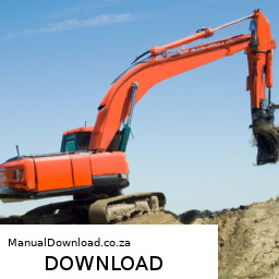
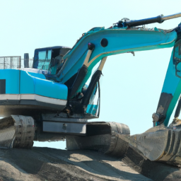
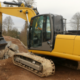
Performing suspension alignment on a Hitachi EX1200-5 Excavator is a complex process that requires a thorough understanding of the machine’s components and systems. click here for more details on the download manual…..
- High tech solutions on Hitachi dump trucks revealed We used in-house technology within the Hitachi group to develop the AC-3 series mining truck. This resulted in better …
- Hitachi EX1200 ARM Cylinder #shortvideo #
Below are detailed steps and descriptions of the tools required for the alignment process.
### Tools and Equipment Needed
– **Laser Alignment Tool**
– A precision tool that uses a laser beam to measure alignment. It helps in ensuring that all axles and suspension components are aligned accurately.
– **Digital Level**
– A digital leveling tool that measures angles and slope; essential for checking the level of the machine and its components during alignment.
– **Torque Wrench**
– A tool used to apply a specific torque to fasteners, ensuring that bolts are tightened to the manufacturer’s specifications.
– **Grease Gun**
– A device for applying lubricant to suspension components, which is crucial for maintaining smooth operation and preventing wear.
– **Measuring Tape**
– A measuring tool used to measure distances between suspension components and ensure correct spacing and alignment.
– **Socket and Ratchet Set**
– A set of various-sized sockets and ratchets to remove and install bolts and nuts on suspension components.
– **Service Manual for Hitachi EX1200-5**
– A comprehensive guide that provides specifications, diagrams, and procedures specific to the Hitachi EX1200-5, ensuring adherence to manufacturer standards.
– **Safety Gear**
– Personal protective equipment (PPE) including gloves, safety glasses, and steel-toed boots to protect the technician during the alignment process.
### Suspension Alignment Process
– **Preparation**
– Ensure the excavator is parked on a flat, stable surface. Engage the parking brake to prevent movement during the alignment process.
– Put on all necessary safety gear.
– **Inspect Suspension Components**
– Thoroughly examine all suspension components, including bushings, joints, and links, for wear or damage. Replace any worn or damaged parts before proceeding with alignment.
– **Lift the Excavator**
– Use a hydraulic jack or appropriate lifting equipment to raise the excavator, allowing access to the undercarriage and suspension components. Secure with jack stands for safety.
– **Check Level and Plumb**
– utilize the digital level to ensure that the excavator is perfectly level before beginning the alignment process. Adjust as necessary.
– **Measure Suspension Geometry**
– Use the measuring tape to take baseline measurements of the suspension components. Document these measurements for comparison after adjustments are made.
– **Laser Alignment Setup**
– Set up the laser alignment tool according to the manufacturer’s instructions. Position the laser at a reference point on the excavator to project a straight line for alignment.
– **Adjust Suspension Components**
– Begin adjusting the suspension components based on the measurements taken. This may involve loosening bolts and repositioning parts to ensure they align with the laser’s reference line.
– Use the torque wrench to tighten bolts to the specified torque settings as per the service manual once adjustments are made.
– **Check Alignment**
– After adjustments, check the alignment using the laser tool and compare with the baseline measurements. Make any necessary fine adjustments to achieve proper alignment.
– **Lubricate Components**
– Use the grease gun to apply lubricant to all moving parts of the suspension system to ensure smooth operation and reduce wear.
– **Final Inspection**
– Conduct a thorough final inspection of all suspension components, ensuring everything is secure and properly aligned.
– Recheck all torque settings to ensure they meet manufacturer specifications.
– **Lower the Excavator**
– Carefully lower the excavator back to the ground and remove any tools or equipment used during the alignment process.
– **Test Operation**
– Before putting the excavator back into regular use, conduct a test operation to ensure that the suspension system functions correctly and that the alignment has been successfully achieved.
### Documentation
– **Record All Findings**
– Document all measurements, adjustments made, and any parts replaced. This information can be valuable for future reference and maintenance.
– **Report to Maintenance Log**
– Update the maintenance log for the Hitachi EX1200-5 with details of the alignment process conducted, including dates, findings, and any parts ordered or replaced.
By following these detailed steps and using the appropriate tools, you can perform a suspension alignment on a Hitachi EX1200-5 Excavator effectively and safely. always refer to the service manual for specific details related to your machine’s model.
The timing belt cover is a crucial component in an internal combustion engine, serving both protective and functional purposes. Typically made from durable plastic or metal, the timing belt cover encases the timing belt, which is responsible for synchronizing the rotation of the crankshaft and camshaft(s). This synchronization is essential for ensuring that the engine’s valves open and close at the correct times in relation to the movement of the pistons, thereby maintaining optimal engine performance and efficiency.
The timing belt cover protects the timing belt from dirt, debris, and moisture, which can lead to premature wear or damage. By sealing off this critical area, the cover helps maintain the integrity of the belt and the components surrounding it. Additionally, the cover often incorporates features such as inspection windows for visual checks, as well as mounting points for other engine components.
In some designs, the timing belt cover also plays a role in the overall aesthetic of the engine bay, contributing to a cleaner and more organized appearance. It is important to periodically inspect the timing belt cover for signs of cracks, leaks, or wear, as these can indicate potential issues with the timing belt itself. A failing timing belt can lead to severe engine damage, making the cover an essential part of the overall engine maintenance regimen.
 and safety equipment.
 and additional guidance.
 and mounting points for any defects that need addressing.
 and amount.
 and engine. Apply
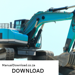
 and a solvent to clean the
 and place jack stands securely under the frame to support it.
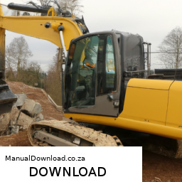
 and eye protection.
 and consult the manual for detailed