Download Takeuchi TB020 operators manual –

book store
Replacing the anti-roll bar on a Takeuchi TB020 excavator involves several steps. click here for more details on the download manual…..


    Takeuchi TB135 Thermostat Change This is a quick video describing the process to install a new thermostat on a Takeuchi TB135 excavator. In this video I describe …
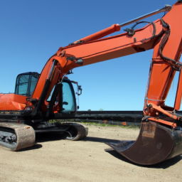
    takeuchi tb020

Below is a reverse order guide on how to perform this replacement:

### Step 6: Reattach Components
– Reinstall any components that were removed to access the anti-roll bar, such as the wheel or track components, If applicable.
– Ensure all bolts and fasteners are tightened to the manufacturer’s specifications.

### Step 5: Install the New Anti-Roll Bar
position the new anti-roll bar in place, aligning it with the mounting points.
– Secure the anti-roll bar with the appropriate bolts and nuts. Make sure they are tightened to the specified torque.

### Step 4: Remove the Old Anti-Roll Bar
– Unscrew and remove any fasteners holding the old anti-roll bar in place.
– Carefully detach the anti-roll bar from its mounting points, ensuring not to damage surrounding components.

### Step 3: Prepare the Work Area
– Ensure that the excavator is on a flat, stable surface and is securely supported with jack stands If necessary.
– Gather all necessary tools and replacement parts before starting the disassembly.

### Step 2: Disconnect the Battery
– For safety, disconnect the battery to prevent any electrical issues during the replacement process.

### Step 1: Perform a Safety Check
– Before starting any repair work, conduct a safety check to ensure you have appropriate personal protective equipment (PPE) and that the equipment is safe to work on.

### Final Notes:
– Always refer to the Takeuchi TB020 service manual for specific torque values and additional instructions Related to your model.
– Dispose of the old anti-roll bar and any other removed components responsibly according to local regulations.

By following these steps in reverse order, you can successfully replace the anti-roll bar on a Takeuchi TB020 excavator.
Air suspension is a type of vehicle suspension system that utilizes compressed air to support the weight of the vehicledownload Takeuchi TB020 s workshop manual 
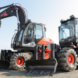
and provide a comfortable ride. Unlike traditional coil or leaf spring systems that rely on metal components, air suspension systems use air-filled bags, commonly referred to as air springs. These bags can be inflated or deflated to adjust the vehicle’s ride height and stiffness, offering a level of customization and adaptability not available with conventional suspensions.

The primary components of an air suspension system include air springs, a compressor, air lines, and an electronic control unit. The air springs, typically made from durable rubber materials, replace the traditional springs and can be adjusted for pressure, allowing the vehicle to maintain a consistent ride height regardless of load. The compressor is responsible for supplying air to the springs, while the electronic control unit monitors and regulates the system based on driving conditions, vehicle load, and driver preferences.

One of the significant advantages of air suspension is its ability to enhance ride quality By absorbing shocks and vibrations from the road. This results in a smoother driving experience, especially on uneven surfaces. Additionally, air suspension provides improved handling characteristics, as the system can dynamically adjust to changing conditions, maintaining optimal contact between the tires and the road. This technology is commonly found in luxury vehicles, heavy-duty trucks, and off-road vehicles, where comfort and load-carrying capability are paramount. Overall, air suspension offers a versatile solution for achieving a balance between performance, comfort, and adaptability in automotive design.

Download KOMATSU PC200 PC200LC-6 PC210LC-6 Maintenance Manual –

owners manual
Exhaust manifold repair on a Komatsu PC200, PC200LC-6, and PC210LC-6 involves careful planning and execution to restore functionality and prevent further damage. click here for more details on the download manual…..


      #komatsu PC210-8 Monitor display available for sale good condition komatsu PC210-8 Monitor display available for sale #9866905244 https://utsengineers.com https://komatsu-uts.business.site/ …

    Below are detailed steps and tools required for the repair:

    ### Tools and Equipment Needed
    – **Socket Set**: A complete metric socket set will be necessary for removing and replacing bolts.
    – **Wrenches**: Both open-end and box-end wrenches in metric sizes will be required for hard-to-reach areas.
    – **Torque Wrench**: To ensure bolts are tightened to manufacturer specifications, preventing future leaks or failures.
    – **Pry Bar**: Useful for removing stubborn components that may be stuck due to heat and corrosion.
    – **Gasket Scraper**: For cleaning old gasket material off the surfaces.
    – **Wire Brush**: To clean rust from the exhaust manifold and Engine block.
    – **Rags or Towels**: For cleaning surfaces and wiping away debris.
    – **Safety Goggles and Gloves**: Personal protective equipment to protect eyes and hands.
    – **Engine Degreaser**: To clean the area around the exhaust manifold before starting repairs.
    – **Replacement Gaskets**: Ensure you have the correct exhaust manifold gaskets for your specific model.
    – **High-Temperature RTV Sealant**: For additional sealing if required or specified by the manufacturer.
    – **Compressed Air**: For blowing out any debris from the exhaust ports.

    ### Repair Steps
    – **Preparation**:
    – Ensure the machine is parked on level ground and the Engine is cool.
    – Disconnect the battery to prevent any electrical issues while working.
    – Gather all tools and replacement parts before starting to minimize downtime.

    – **Remove the Engine Cover**:
    – If applicable, remove any Engine covers that obstruct access to the exhaust manifold.

    – **Inspect the Area**:
    – Use the wire brush and Engine degreaser to clean around the manifold. This helps prevent debris from falling into the Engine during disassembly.

    – **Disconnect Exhaust and Intake Components**:
    – Remove any pipes or hoses connected to the exhaust manifold.
    – Detach the intake manifold if necessary to gain better access.

    – **Remove Exhaust Manifold Bolts**:
    – Use the appropriate socket and wrench to remove the bolts securing the exhaust manifold to the Engine block.
    – Keep track of the bolt locations as they may be of different lengths.

    – **Remove the Exhaust Manifold**:
    – Carefully pry the exhaust manifold away from the Engine block. Avoid using excessive force to prevent damaging the Engine block.

    – **Inspect the Exhaust Manifold**:
    – Check for cracks, warping, or other damage. If the manifold is severely damaged, it may need to be replaced rather than repaired.

    – **Clean the Surfaces**:
    – Use a gasket scraper to remove old gasket material from the Engine block and exhaust manifold surfaces.
    – Ensure the surfaces are smooth and free from debris.

    – **Install New Gasket**:
    – Place a new exhaust manifold gasket onto the Engine block. Ensure it is properly aligned with the bolt holes.

    – **Reinstall Exhaust Manifold**:
    – Carefully position the exhaust manifold over the gasketdownload KOMATSU PC200 PC200LC 6 PC210LC 6 workshop manual and align it with the bolt holes.
    – Hand-tighten the bolts to hold the manifold in place before fully tightening.

    – **Torque the Bolts**:
    – Using a torque wrench, tighten the manifold bolts to the manufacturer’s specified torque settings in the correct sequence to ensure even pressure.

    – **Reconnect Exhaust and Intake Components**:
    – Reattach any pipes, hoses, or components that were disconnected during the process.

    – **Final Checks**:
    – Inspect all connections to ensure they are secure.
    – Reconnect the battery and start the Engine to check for leaks or unusual noises.

    – **Testing**:
    – Let the Engine run for a few minutes and observe the exhaust manifold area for any signs of leaks. If everything is functioning properly, the repair is complete.

    ### Safety Considerations
    – Always wear safety goggles and gloves to protect yourself from debris and hot surfaces.
    – Ensure the work area is well-ventilated, especially when working with degreasers and sealants.
    – Be cautious of hot components, as the exhaust system can retain heat long after the Engine is turned off.

    By following these steps and using the proper tools, you can effectively repair the exhaust manifold on a Komatsu PC200, PC200LC-6, and PC210LC-6, helping to maintain the machine’s performance and efficiency.
    The fuse box, also known as a fuse panel or fuse block, is a critical component of a vehicle’s electrical system. It serves as a central hub for protecting the various electrical circuits within the automobile by containing fuses that prevent overcurrent conditions. When electrical devices draw more current than what they are designed for, the fuse—typically a small, thin piece of metal within a plastic casing—will melt or break the circuit, effectively stopping the flow of electricity. This protection mechanism helps prevent damage to wiring and electronic components, which could lead to costly repairs or even fire hazards.

    In modern vehicles, the fuse box is usually located under the dashboard, in the Engine compartment, or sometimes in the trunk, depending on the design of the vehicle. Inside the fuse box, each fuse corresponds to a specific electrical component or system, such as headlights, radio, power windows, and other accessories. The fuse box is marked with diagrams or labels indicating the function of each fuse, making it easier for technicians and vehicle owners to identify which fuse may need replacement in case of an electrical issue.

    Additionally, some fuse boxes may include relays, which are electromechanical switches used to control larger electrical loads, further enhancing the vehicle’s electrical management. Regular inspection and maintenance of the fuse box can contribute to the overall reliability and safety of the vehicle’s electrical system, ensuring that all components function as intended and reducing the risk of electrical failures on the road.

    Download Kobelco K905LC-II Parts-

    do your own repairs
    Replacing the input shaft bearing on a Kobelco K905LC II excavator involves several steps, and it’s important to follow the manufacturer’s guidelines for safety and accuracy. click here for more details on the download manual…..


      Engine Mounting Rubber 2416Z574 2416Z573 2416Z498 for Kobelco K904-2 SK100-3 SK120-3 SK120LC-3 8 PCS Engine Mounting Rubber Cushion 2416Z574 2416Z573 2416Z498 for Kobelco Excavator K904-2 K904L-2 K905-2 …

    Below is a detailed description of the components and the process involved in replacing the input shaft bearing.

    ### Components Involved:

    1. **Input shaft Bearing**: This is the bearing that supports the input shaft and allows it to rotate smoothly. It is crucial for the proper functioning of the drivetrain.

    2. **Input Shaft**: The shaft that transmits power from the engine to the drivetrain. It connects to the transmission.

    3. **Bearing Housing**: This is the component that holds the input shaft bearing in place. It is often bolted to the transmission case.

    4. **Gasket/Seals**: Gaskets and seals prevent leaks and keep contaminants out of the bearing housing.

    5. **Fasteners**: Bolts and nuts that secure the bearing housing and other components.

    6. **Tools**: Common tools required for this job include wrenches, sockets, a bearing puller, a hammer, a torque wrench, and possibly special tools designed for bearing installation.

    ### Tools Required:

    – Socket set
    – Wrench set
    – Torque wrench
    – Bearing puller
    – Hammer
    – Screwdrivers
    – Pliers
    – Clean cloths
    – Lubricant (grease or oil)
    – Safety equipment (gloves, goggles)

    ### Step-by-Step Replacement Procedure:

    1. **Safety Precautions**:
    – Park the excavator on a flat surface and engage the parking brake.
    – Disconnect the battery to prevent any electrical hazards.
    – Use safety glasses and gloves for protection.

    2. **Remove the Cover**:
    – Locate the cover over the input shaft bearing. This may involve removing access panels or covers.
    – Use the appropriate tools to remove any bolts or fasteners securing the cover.
    – Carefully lift off the cover and set it aside.

    3. **Drain Transmission Fluid**:
    – If necessary, drain the transmission fluid to prevent spills during the bearing replacement.
    – Locate the drain plug on the transmission case and remove it to allow the fluid to drain completely.

    4. **Remove the Input Shaft**:
    – Depending on the design, you may need to remove other components or parts that obstruct access to the input shaft.
    – Use a bearing puller to remove the input shaft from its position if it is stuck.
    – Gently tap it out with a hammer if necessary, ensuring that you do not damage any surrounding components.

    5. **Remove the Old Bearing**:
    – Once the input shaft is out, access the bearing housing where the input shaft bearing is located.
    – Use the bearing puller to remove the old input shaft bearing. Be careful not to damage the bearing housing.
    – Inspect the bearing housing for any signs of wear or damage.

    6. **Clean the Area**:
    – Clean the bearing housingdownload Kobelco K905LC II Parts workshop manual and the surrounding area to remove any debris or old gasket material.
    – Use a clean cloth and appropriate cleaning solution if necessary.

    7. **Install the New Bearing**:
    – Apply a thin layer of lubricant to the new input shaft bearing.
    – Carefully place the new bearing into the bearing housing.
    – Use a bearing installation tool or a soft-faced hammer to tap the bearing into place gently. Ensure it is seated evenly.

    8. **Reinstall the Input Shaft**:
    – Align the input shaft with the new bearing and insert it back into position.
    – Ensure it is seated correctly and rotates smoothly.

    9. **Reattach the Cover**:
    – If there is a gasket or seal, replace it with a new one to prevent leaks.
    – Reattach the cover over the input shaft bearing and secure it with the appropriate fasteners.
    – Torque the bolts to the manufacturer’s specifications.

    10. **Refill Transmission Fluid**:
    – If you drained the transmission fluid earlier, refill it to the appropriate level.
    – Check for any leaks around the newly installed bearing.

    11. **Reconnect the Battery**:
    – Reconnect the battery and ensure all electrical connections are secure.

    12. **Test the Excavator**:
    – Start the excavator and perform a test run to ensure everything is functioning correctly. Listen for any unusual noises and check for leaks.

    ### Conclusion:
    Replacing the input shaft bearing on a Kobelco K905LC II excavator requires careful attention to detail and adherence to safety protocols. Following these detailed steps will help ensure a successful replacement. Always consult the operator’s manual or service manual for specific torque values and additional procedures related to your excavator model.
    The grille emblem is a distinctive and often iconic component found on the front of many vehicles, typically positioned prominently within the vehicle’s grille. This emblem serves multiple purposes, both functional and aesthetic. Primarily, it acts as a branding element, showcasing the manufacturer’s logo or name, which contributes to the vehicle’s identity and recognition. Whether it features a stylized letter, a symbol, or a combination of both, the grille emblem is a critical aspect of a car’s overall design language.

    Beyond branding, the grille emblem can play a role in the vehicle’s aerodynamics. In some cases, it is designed to enhance airflow to the engine or cooling systems, which can be crucial for performance. The placement of the emblem often aligns with the vehicle’s design philosophy, complementing the lines and contours of the front fascia.

    Additionally, grille emblems can vary in materials and finishes, ranging from chrome and metallic finishes to more modern, minimalist designs using plastic or composite materials. Some emblems are illuminated, adding a contemporary touch and improving visibility in low-light conditions. The grille emblem not only contributes to the visual appeal of the vehicle but also helps establish a connection between the driver and the brand, making it a significant element in automotive design and marketing.

    Download CASE CX290B Excavator Service Manual –

    books
    Tire rotation is an important maintenance task that can help extend the life of the tires on your CASE CX290B excavator. click here for more details on the download manual…..


      CASE Excavator CX290B Part Numbers & Equipment Tour Inspection | FridayParts Video Catalog CASE CX290B replacement spare part numbers lookup. Subscribe Our Channel! Easily match the right part numbers to your …

      Excavator Case CX290 leaking hydraulic cylinder. Sorry, little shaky vid.

    The following detailed description outlines the components involved in tire rotation and the steps to perform it effectively.

    ### Components Involved in Tire Rotation

    1. **Tires:**
    – **Size and Type:** The CASE CX290B typically uses large rubber tires designed for heavy-duty applications. Ensure you have the right size and type for your model (e.g., 20.5-25 or comparable).
    – **Tread Depth:** Check the tread depth before rotation to ensure they are within safe operating limits.

    2. **Wheels:**
    – **Rims:** The wheels that hold the tires in place; ensure they are free from damage, rust, or corrosion.
    – **Lug Nuts:** The fasteners securing the tires to the wheels; they must be properly torqued.

    3. **Jacks and Jack Stands:**
    – **Hydraulic Floor Jacks:** To lift the excavator safely.
    – **Jack Stands:** To provide stable support once the excavator is lifted.

    4. **Torque Wrench:**
    – To ensure that the lug nuts are tightened to the manufacturer’s specifications.

    5. **Tire Pressure Gauge:**
    – For measuring tire pressure before and after rotation.

    6. **Protective Equipment:**
    – Gloves, safety goggles, and steel-toed boots for personal protection.

    ### steps to Rotate Tires on a CASE CX290B Excavator

    1. **Preparation:**
    – **Safety First:** Before starting, park the excavator on a flat, stable surface. Engage the parking brake and turn off the engine.
    – **Gather Tools:** Collect all necessary tools and equipment, including jacks, jack stands, a torque wrench, and a tire pressure gauge.

    2. **Inspect Tires:**
    – Check the condition of all tires for wear, cracks, or punctures. Measure the tread depth and check for uneven wear patterns.

    3. **Lifting the Excavator:**
    – **Position the Jack:** Place the hydraulic jack under the designated lifting points of the excavator (refer to the operator’s manual for specific locations).
    – **Lift the Excavator:** Raise the excavator until the tires are off the ground.
    – **Secure with Jack Stands:** Once lifted, place jack stands under the machine to ensure stability. Never work under a vehicle supported only by a jack.

    4. **Removing the Tires:**
    – **Loosen Lug Nuts:** Using a tire iron, slightly loosen the lug nuts on the tires you plan to rotate. Do not completely remove them yet.
    – **Remove Lug Nuts and Tires:** Once the lug nuts are loosened, fully remove them and take off the tires. Keep the lug nuts in a safe place.

    5. **Tire Rotation Pattern:**
    – **Identify Rotation Pattern:** For excavators, a common rotation pattern is the “cross” pattern (front tires to rear, rear tires to front) or as specified in the operator’s manual.
    – **Rotate Tires:** Position the tires according to the predetermined rotation pattern.

    6. **Reinstalling Tires:**
    – **Place Tires on Rims:** Align the tires with the wheel studs and place them back on the rims.
    – **Hand Tighten Lug Nuts:** Start threading the lug nuts onto the wheel studs by hand to avoid cross-threading.
    – **Tighten Lug Nuts:** Use a torque wrench to tighten the lug nuts to the manufacturer’s specified torque (check the operator’s manual for the correct torque value). Tighten in a star pattern to ensure even pressure.

    7. **Lowering the Excavator:**
    – **Remove Jack Sdownload CASE CX290B Excavator workshop manual
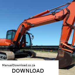
tands:** Carefully remove the jack stands.
    – **Lower the Excavator:** Slowly lower the excavator back to the ground using the hydraulic jack.

    8. **Final Checks:**
    – **Check Tire Pressure:** Use a tire pressure gauge to check and adjust each tire to the recommended pressure as specified in the operator’s manual.
    – **Inspect for Any Issues:** After rotation, inspect the tires and wheels to ensure everything is secure and in good condition.

    9. **Documentation:**
    – Log the tire rotation in the maintenance records for future reference.

    ### Conclusion

    Tire rotation on a CASE CX290B excavator is a straightforward process that can significantly improve tire longevity and performance. Following these detailed steps and safety precautions will help ensure a successful tire rotation and maintain the equipment in optimal working condition. Always refer to the operator’s manual for specific details related to your machine model.
    A tie rod end is a crucial component of a vehicle’s steering system, playing a vital role in maintaining proper alignment and steering control. It serves as a connection point between the steering knuckle and the steering rack or center link, facilitating the transfer of motion from the steering wheel to the wheels. Essentially, the tie rod end acts as a pivot point that allows the wheels to turn in accordance with the driver’s input.

    Typically made of forged steel or other durable materials, tie rod ends are designed to withstand significant forces and stresses encountered during driving. They consist of a ball joint at one end, which allows for angular movement, and a threaded shaft at the other end that connects to the steering assembly. This design enables the tie rod end to accommodate the suspension’s movement while maintaining the necessary alignment for optimal vehicle handling.

    Over time, tie rod ends can wear out due to factors like road conditions, driving habits, and exposure to environmental elements. Signs of a failing tie rod end may include uneven tire wear, steering play, or a clunking noise when turning. Regular inspection and timely replacement of worn tie rod ends are essential to ensure safe driving and maintain the overall performance of the vehicle’s steering system. Properly functioning tie rod ends contribute to precise steering response, enhanced stability, and improved tire longevity.

    Download Komatsu PC1250-8 manual collection. 4 x manuals –

    service manual
    Repairing the suspension knuckle on a Komatsu PC1250-8 involves a series of detailed steps. click here for more details on the download manual…..

        Here’s a reverse order breakdown of the process, assuming you have access to the necessary manuals for specific torque specifications and detailed diagrams.

        ### 8. Final Assembly
        1. **Reinstall the Wheel Hub**: Attach the wheel hub to the suspension knuckle and secure it with bolts, ensuring they are torqued to the manufacturer’s specifications.
        2. **Reconnect the Brake Components**: If the brake system was removed, reinstall it according to the service manual.
        3. **Install New Seals and Gaskets**: Ensure that all new seals and gaskets are properly fitted to prevent leaks.

        ### 7. Suspension Knuckle Installation
        1. **Position the Knuckle**: Carefully align the suspension knuckle with the axle housing.
        2. **Secure the Knuckle**: Use the appropriate bolts to secure the knuckle, following the recommended torque settings.

        ### 6. Bearing and Seal Replacement
        1. **Install Bearings**: If bearings were replaced, ensure they are seated properly in the knuckle.
        2. **Replace Seals**: install new seals to prevent oil leaks.

        ### 5. Disassembly of the Suspension Knuckle
        1. **Remove the Knuckle**: Detach the suspension knuckle from the axle housing by removing the mounting bolts.
        2. **Take Out Bearings and Seals**: remove any bearings and seals from the knuckle for inspection or replacement.

        ### 4. Inspect Components
        1. **Check for Damage**: Inspect the knuckle, bearings, seals, and other related components for wear or damage.
        2. **Clean Parts**: Thoroughly clean all parts to be reused to remove dirt and debris.

        ### 3. Preparation for Repair
        1. **Gather Tools and Parts**: Collect all the necessary tools, replacement parts, and manuals.
        2. **Ensure Safety**: Use proper safety gear and ensure the work area is clear.

        ### 2. Diagnosis of the Issue
        1. **Identify Symptoms**: Confirm that the suspension knuckle is the source of the problem (e.g., unusual noises, play in the wheel).
        2. **Consult Manuals**: Refer to the service manuals for troubleshooting guidelines specific to the Komatsu PC1250-8.

        ### 1. Safety Precautions
        1. **Park the Equipment**: Ensure that the Komatsu PC1250-8 is parked on a flat surface.
        2. **Engage the Parking Brake**: Engage the parking brake to prevent movement.
        3. **Disconnect the Battery**: Disconnect the battery to ensure safety while working on electrical components.

        ### Conclusion
        Following these reverse order steps will help in successfully repairing the suspension knuckle of a Komatsu PC1250-8. Always refer to the specific service manuals for detailed procedures, torque specifications,download Komatsu PC1250 8. 4 x manuals workshop manual and safety instructions.
        A CD player, or compact disc player, is an electronic device designed to read and play audio CDs, which store digital audio data on optical discs. This component became a standard feature in vehicles starting in the late 1980s and throughout the 1990s and early 2000s, serving as a primary source of music for many drivers and passengers.

        The CD player consists of several key components: a laser assembly, a spindle motor, and a digital-to-analog converter (DAC). The laser assembly reads the disc’s encoded data by shining a laser onto the surface of the CD, which is a reflective medium. The information is stored in the form of tiny pits and lands that represent binary data. As the disc spins, the laser detects these variations and converts them into audio signals through the DAC, allowing the sound to be amplified and played through the vehicle’s speakers.

        Despite the rise of digital streaming services and portable music players, which have increasingly diminished the popularity of physical media, many car manufacturers still include CD players in their audio systems, catering to consumers who appreciate the tactile experience of handling CDs or who have extensive physical music collections. However, as technology continues to evolve, the relevance of CD players is waning, with many newer car models forgoing them in favor of more modern connectivity options like Bluetooth and USB ports. Nonetheless, the CD player remains a nostalgic component for many, symbolizing a significant era in automotive audio technology.

        Download HYUNDAI R55W-9A Wheel Excavator Service Repair Manual –

        online
        Repairing the overdrive system on a Hyundai R55W 9A Wheel Excavator can be a complex task, especially for someone with little mechanical experience. click here for more details on the download manual…..


          Hyundai R380LC-9 Excavator Hydraulic Flow Adjustment to the Thumb http://www.sheelysupply.com Procedure to adjust the speed of the the thumb cylinder. Speed up or slow down. Industrial Diesel …

          360 gradusli Hyundai R55W EXCAVATOR HYUNDAI | R55w 1- Yuklab berish 2- Eksport deklaratsiya 3- Sertifikat 4- O`zbekiston bo`ylab yetkazib berish 5- …

        However, I’ll break it down into simpler steps and concepts to make it more understandable.

        ### What is Overdrive?
        In the context of excavators and heavy machinery, “overdrive” often refers to a mechanism that allows the engine to run at lower RPMs while maintaining speed. This improves fuel efficiency and reduces engine wear.

        ### Common Signs of Overdrive Issues
        Before you start any repair, it’s essential to know the symptoms of an overdrive problem:
        – Unusual noises when shifting.
        slipping or not engaging into overdrive.
        – Warning lights on the dashboard.
        – Poor fuel efficiency.

        ### Basic Steps for Overdrive Repair

        #### 1. **Safety First**
        – **Turn Off the Machine:** Ensure the excavator is turned off and the key is removed.
        – **Engage the Parking Brake:** This prevents any movement during the repair.
        – **Wear Safety Gear:** Use gloves and safety glasses to protect yourself.

        #### 2. **Locate the Overdrive Components**
        – **Consult the Manual:** The user manual for the Hyundai R55W 9A will have diagrams showing where the overdrive components are located.
        – **Identify Components:** Look for the transmission (where the overdrive is integrated), wiring harnesses, and any sensors related to the overdrive system.

        #### 3. **Check Fluid Levels**
        – **Transmission Fluid:** Low fluid levels can cause overdrive issues. Check the fluid level and quality (color and smell).
        – **Add Fluid if Necessary:** If it’s low, add the recommended type of transmission fluid as per the manual.

        #### 4. **Inspect Wiring and Connections**
        – **Look for Damage:** Inspect the wiring harness connected to the overdrive system. Look for frayed wires, loose connections, or corrosion.
        – **Reconnect Loose Wires:** If you find any loose connections, reconnect them securely.

        #### 5. **Check the Overdrive Switch**
        – **Locate the Switch:** This is typically found on the gear shift or dashboard.
        – **Test the Switch:** Ensure it is functioning correctly. You can do this by checking if it clicks when pressed and making sure it returns to its original position.

        #### 6. **Examine the Transmission**
        – **Check for Leaks:** Look under the machine for any signs of fluid leaks. Leaks can lead to low fluid levels.
        – **Listen for Sounds:** When the machine is running, listen for any unusual noises from the transmission area.

        #### 7. **Test Drive the Excavator**
        – **After making adjustments, take the excavator for a short test drive.**
        – **Observe Performance:** Pay attention to how the machine shifts into overdrive. It should engage smoothly without slipping.

        #### 8. **Consult a Professional**
        – If you’re still experiencing problems or if anything seems too complicated, it’s best to consult a mechanic who specializes in heavy machinery.

        ### Final Thoughts
        Repairing the overdrive on a Hyundai R55W 9A Wheel Excavator requires a basic undersdownload HYUNDAI R55W 9A Wheel Excavator workshop manualtanding of its components and some troubleshooting skills. always prioritize safety and don’t hesitate to seek help if needed. Regular maintenance can help prevent issues with the overdrive and prolong the life of your excavator.
        The alternator bracket is a crucial component in an automobile’s engine compartment, serving as the mounting point for the alternator. The alternator itself is responsible for converting mechanical energy from the engine into electrical energy, which is essential for recharging the vehicle’s battery and powering electrical systems while the engine is running. The bracket ensures that the alternator is securely fastened in place, maintaining the proper tension on the drive belt that connects it to the engine’s crankshaft.

        Typically made from durable materials such as steel or aluminum, the alternator bracket is designed to withstand the vibrations and stresses that occur during engine operation. Its design is often specific to the make and model of the vehicle, ensuring a perfect fit and optimal performance. The bracket not only supports the weight of the alternator but also plays a role in aligning it correctly with the other engine components, such as the water pump and power steering pump, to ensure smooth operation and minimal wear on the drive belt.

        In addition to its structural role, the alternator bracket may also include features such as adjustment slots to allow for belt tensioning. Proper tension is critical, as it prevents slippage and ensures that the alternator operates efficiently. A damaged or poorly aligned alternator bracket can lead to various issues, including reduced electrical output, premature wear on the alternator, and potential engine performance problems. Therefore, maintaining the integrity of the alternator bracket is essential for the overall health of the vehicle’s electrical system.

        Download Hyundai Robex R35-7 Service Manual –

        repair
        Replacing the shift solenoid on a Hyundai Robex R35-7 (a compact excavator) involves several steps and requires attention to detail to ensure proper installation and functionality. click here for more details on the download manual…..


          Brush moving! #excavator #hyundai #ourdoors

          seal kit Hyundai seal , #sealkit , #oilseal , #MotorSealKit, #CylinderSealKit, #HydraulicCylinderSealKit, #MasterCylinderSealKit, #hyundai. TAILOR …

        below is a detailed guide, including descriptions of the components involved:

        ### Tools and Materials Needed
        1. **Tools:**
        – Socket set (metric)
        – Wrench set (metric)
        – Screwdrivers (flathead and Phillips)
        – Torque wrench
        – Pliers
        – Wire cutters/strippers
        – Multimeter (for electrical testing)

        2. **Materials:**
        – Replacement shift solenoid
        – New O-ring or gasket (if applicable)
        – Clean rags
        – Engine oil or lubricant (for sealing surfaces)
        – Loctite (if required for screws)

        ### Safety Precautions
        – Ensure the excavator is parked on a level surface.
        – Disconnect the battery to prevent electrical shorts or accidental operation.
        – Wear safety gloves and goggles.

        ### Detailed Replacement Steps

        #### Step 1: Prepare the Work Area
        – Clear the area around the excavator to have enough space to work.
        – Gather all required tools and materials.

        #### Step 2: Access the Shift Solenoid
        – **Locate the Shift Solenoid:**
        – The shift solenoid is typically located near the transmission or hydraulic control unit. Refer to the operator’s manual for the exact location.
        – **Remove Engine Cover / Access Panels:**
        – If necessary, remove any engine covers or access panels to reach the solenoid. This may involve unscrewing bolts or clips.

        #### Step 3: Disconnect electrical Connector
        – **Identify the Connector:**
        – Locate the electrical connector that leads to the shift solenoid.
        – **Unplug the Connector:**
        – Gently pull the connector away from the solenoid. If it is stuck, use a flathead screwdriver to carefully pry it loose. Be cautious not to damage the connector or wiring.

        #### Step 4: Remove the Old Shift Solenoid
        – **Loosen the mounting Bolts:**
        – Use the appropriate socket or wrench to remove the bolts securing the shift solenoid. Keep these bolts, as you will need them for the new solenoid.
        – **Remove the Solenoid:**
        – Once the bolts are removed, gently pull the solenoid out. there may be an O-ring or gasket, which should be replaced with the new solenoid. If it is stuck, gently twist it to break any seal.

        #### Step 5: Install the New Shift Solenoid
        – **Prepare the New Solenoid:**
        – Before installation, apply a small amount of engine oil or lubricant to the new O-ring or gasket to ensure a good seal.
        – **Position the New Solenoid:**
        – Align the new shift solenoid with the mounting holes and gently insert it into place.
        – **Secure the Solenoid:**
        – Install the mounting bolts and tighten them to the manufacturer’s specifications using a torque wrench. Refer to the operator’s manual for the correct torque values.

        #### Step 6: Reconnect electrical Connector
        – **Plug in the Connector:**
        – Firmly reconnect the electrical connector to the new solenoid until you hear a click, indicating it is securely in place.

        #### Step 7: Reassemble Any Removed Components
        – **Replace Engine Cover / Access Panels:**
        – If you removed any engine covers or access panels, reattach them using the original screws or clips.

        #### Step 8: Reconnect the Battery
        – Reconnect the battery terminals, ensuring they are tightened securely.

        #### Step 9: Test the System
        – **Start the Excavator:**
        – Start the enginedownload Hyundai Robex R35 7 workshop manual and allow it to warm up. Check for any warning lights or errors on the control panel.
        – **Test Shift Functionality:**
        – Engage the transmission or hydraulic functions to ensure the shift solenoid is operating correctly. Listen for any unusual sounds and observe the system for any leaks.

        ### Conclusion
        Replacing the shift solenoid on a Hyundai Robex R35-7 requires careful handling and attention to detail. By following these steps and ensuring all components are correctly installed, you can help maintain the proper functioning of the excavator’s transmission or hydraulic system. If you encounter any issues during the process, consult the operator’s manual or seek assistance from a qualified technician.
        A shift boot, also known as a gear shift boot, is a vital component found in vehicles with manual transmissions and some automatic models. It serves both functional and aesthetic purposes, positioned around the gear shifter to cover and protect the mechanical parts beneath. Typically made from materials such as leather, vinyl, or rubber, the shift boot provides a barrier against dust, dirt, and debris that could potentially enter the transmission system, thereby prolonging the life of the internal components.

        From a design perspective, the shift boot enhances the overall interior appearance of the vehicle, adding a touch of style and sophistication. It often comes in various colors and textures to match or complement the vehicle’s interior decor. Additionally, the shift boot can be designed to feature stitching or other decorative elements, making it an integral part of the car’s aesthetic appeal.

        Functionally, the shift boot also plays a role in reducing noise and vibration that may emanate from the transmission. By providing a snug fit around the gear lever, it can help minimize the sound produced during gear shifts, contributing to a more comfortable driving experience. In some vehicles, the shift boot may also be equipped with features like a boot collar to ensure it remains securely in place.

        Overall, the shift boot is an essential component that combines protective, functional, and aesthetic elements, contributing to both the performance and visual appeal of the vehicle’s interior.

        Download VOLVO EC210B NC Excavator Service Repair Manual –

        repair manual
        Replacing the shift solenoid on a Volvo EC210B NC Excavator involves several steps and requires specific tools and preparations. click here for more details on the download manual…..


          Voltage Regulator Hella / Alternator Charging Relay Bosch / Battery Charge #volvo140 #alternator Today we’re looking at charging regulator relays. Bosch relay OEM for Volvo and Hella as alternative solution. And, of course …

          EICHER engine 8000

        Below is a detailed description of the entire process, including the necessary tools:

        – **Safety Precautions**
        – **Personal Protective Equipment (PPE)**: Ensure to wear safety glasses, gloves, and steel-toed boots to protect yourself during the procedure.
        – **Work Area Preparation**: Clear the work area of debris and ensure the excavator is on stable ground. Use cones or barriers to restrict access to the work area.

        – **Tools Required**
        – **Socket Set**: A complete socket set (metric) to remove bolts and nuts securing the solenoid and other components.
        – **Wrench Set**: Open-end and adjustable wrenches for various fasteners.
        – **Screwdrivers**: Flathead and Phillips screwdrivers for any cover or clamp removal.
        – **Pliers**: Needle-nose and regular pliers for handling small connectors and clips.
        – **Torque Wrench**: To ensure bolts are tightened to manufacturer specifications.
        – **Multimeter**: For testing the electrical connections and ensuring the new solenoid functions properly.
        – **Shop Towels**: To clean any spilled fluids and keep the work area tidy.
        – **Container for Fluids**: To catch any hydraulic fluid that may leak during the replacement process.
        – **Replacement Shift Solenoid**: Ensure you have the correct solenoid for your specific model.

        – **Preparation Steps**
        – **Disconnect the Battery**: Start by disconnecting the negative terminal of the battery to prevent any electrical short circuit.
        – **Hydraulic System Depressurization**: If applicable, relieve any pressure in the hydraulic system by following the manufacturer’s guidelines to avoid leaks or accidents.

        – **Accessing the Shift Solenoid**
        – **Locate the Shift Solenoid**: Identify the location of the shift solenoid, which is typically found on the transmission or hydraulic valve block.
        – **Remove Any Obstructions**: If there are any covers, shields, or components blocking access to the solenoid, carefully remove them using the appropriate tools.

        – **Removing the Old Shift Solenoid**
        – **Disconnect Electrical Connections**: Carefully unplug the electrical connectors from the solenoid. Use pliers if necessary to release clips or locks.
        – **Remove Bolts**: Using the socket set, remove the bolts securing the solenoid. Keep these bolts for reinstallation if they are in good condition.
        – **Take Out the Solenoid**: Gently pull the solenoid out from its mounting position. Be cautious of any hydraulic fluid that may leak out.

        – **Installing the New Shift Solenoid**
        – **Prepare the New Solenoid**: Inspect the new solenoid for damage and ensure it matches the specifications of the old one.
        – **Install the New Solenoid**: Position the new solenoid in its mounting location and secure it with the previously removed bolts, ensuring they are snug But not overtightened.
        – **Reconnect Electrical Connections**: Plug the electrical connectors back into the new solenoid, ensuring a securedownload VOLVO EC210B NC Excavator workshop manual and correct fit.

        – **Reassemble Any removed Components**
        – **Replace Covers and Shields**: Reinstall any covers or components that were removed to access the solenoid, ensuring all fasteners are tightened properly.

        – **Final Steps**
        – **Reconnect the Battery**: Reconnect the negative terminal of the battery.
        – **Check Hydraulic Fluid Levels**: Inspect hydraulic fluid levels and add fluid if necessary.
        – **Test the New Solenoid**: Start the excavator and test the operation of the transmission or hydraulic system to ensure the new solenoid is functioning correctly. Use a multimeter to check for proper voltage at the solenoid if needed.

        – **Cleanup**
        – **Dispose of Old Parts**: Properly dispose of the old solenoid and any other materials used during the replacement.
        – **Clean Work Area**: Ensure the work area is clean and free of tools and debris to maintain safety.

        By following these detailed steps, you can effectively replace the shift solenoid on a Volvo EC210B NC Excavator. Always refer to the specific service manual for your model for any unique instructions or specifications.
        An ashtray is a small receptacle designed to hold ash and cigarette butts, primarily used in vehicles to accommodate smokers. Traditionally, ashtrays were common fixtures in cars, serving as a practical solution for managing waste generated by smoking. Typically made from materials such as metal, ceramic, or durable plastic, an ashtray is designed to withstand heat and minimize the risk of fire. The interior is often lined or shaped to facilitate easy disposal and cleanup, with a slightly raised rim to contain ash and debris.

        In terms of design, ashtrays can vary significantly between different car models and eras. Older vehicles often featured built-in ashtrays integrated into the dashboard or center console, providing a discreet and accessible location for smokers. Many modern vehicles have shifted away from incorporating dedicated ashtrays, reflecting a broader societal trend toward reduced smoking and increased environmental awareness. Instead, some cars offer multifunctional storage compartments that can serve as makeshift ashtrays.

        The decline of the traditional ashtray in cars is also tied to changing regulations and public health campaigns aimed at reducing smoking. As a result, many contemporary vehicles are designed with a focus on promoting a smoke-free environment, and the ashtray has become less common in new models. Nevertheless, ashtrays remain a nostalgic symbol of car culture for many and continue to be available as aftermarket accessories for those who still smoke while driving.

        Download HYUNDAI ROBEX 35-7, R35-7 MINI Excavator Service Repair Manual –

        discount
        Repairing the windshield on a Hyundai Robex 35-7 mini excavator can seem daunting, especially if you have little mechanical experience. click here for more details on the download manual…..


          Hyundai and Cummins Inc. Collaborate on Electric Prototype R35E Compact Excavator Hyundai and Cummins Inc. collaborated in developing the electric-powered Hyundai R35E compact excavator to meet a growing …

          Mini Excavator | Robex 35z-9 | Hyundai Mini Excavator | Features And Specification | YouTube Tami… Don’t Click This Link : https://bit.ly/3qwBaK5 Welcome To My Channel YouTube Tamilan!!!!!! In This Video Your Are Featured with …

        However, with the right tools and a step-by-step approach, you can handle this task. Here’s a simplified guide:

        ### Tools and Materials Needed:
        1. **Safety Glasses**: Protect your eyes.
        2. **Gloves**: Protect your hands.
        3. **Screwdriver Set**: To remove any screws or fasteners.
        4. **Trim Removal Tool**: To safely take off any trim without damaging it.
        5. **Replacement Windshield**: Make sure it’s the correct size and type for your mini excavator.
        6. **Sealant or Adhesive**: Depending on how the windshield is held in place.
        7. **Clean Rags**: To clean the surfaces.
        8. **Putty Knife or Scraper**: To remove old adhesive if needed.

        ### Steps to Repair the Windshield:

        1. **Safety First**:
        – Wear safety glasses and gloves to protect yourself from shards of glass or debris.

        2. **Assess the Damage**:
        – Determine if the windshield can be repaired or if it needs to be replaced. small chips can sometimes be filled, while larger cracks or broken glass will require a full replacement.

        3. **Gather Your Tools and Materials**:
        – Get everything you need close by to avoid running back and forth.

        4. **Remove the Old Windshield**:
        – **Locate Fasteners**: Check around the edges of the windshield for screws or bolts holding it in place. Use your screwdriver to remove them.
        – **Remove Trim**: If there is any trim around the windshield, use the trim removal tool to gently pry it off.
        – **Cut Away Adhesive**: If the windshield is glued in, use a putty knife or scraper to carefully cut through the adhesive around the edges.

        5. **Take Out the Windshield**:
        – Once all fasteners and adhesive are cut, carefully lift the old windshield out. If it’s broken, be cautious of sharp edges.

        6. **Prepare the Frame**:
        – Clean the frame where the windshield will sit, removing old adhesive and debris using a clean rag and scraper if necessary.

        7. **Install the New Windshield**:
        – **Apply Sealant/Adhesive**: If your new windshield requires adhesive, apply it around the edges of the frame following the manufacturer’s instructions.
        – **Position the Windshield**: Carefully lift the new windshield into place. Align it properly with the frame.
        – **Press Firmly**: Make sure it sits snugly against the adhesive.

        8. **Secure the Windshield**:
        – Reinstall any screws or fasteners you removed earlier to hold the windshield in place.
        – Replace any trim pieces you removed, ensuring they are securely fitted.

        9. **Final Check**:
        – Inspect your work to ensure everything is securedownload HYUNDAI ROBEX 35 7 R35 7 MINI Excavator workshop manual and that the windshield is properly seated.
        – Remove any excess adhesive that may have squeezed out around the edges.

        10. **Allow to Cure**:
        – If you used adhesive, allow it to cure as per the manufacturer’s instructions before using the excavator.

        ### Tips:
        – **Take Your Time**: Don’t rush through the process; a careful approach ensures a better fit and finish.
        – **Consult the Manual**: If you have the operator’s manual for the Hyundai Robex 35-7, it may have specific instructions or diagrams for your model.
        – **Consider Professional Help**: If you feel unsure at any point, it’s perfectly okay to call a professional for assistance.

        By following these steps, you should be able to replace the windshield on your Hyundai Robex 35-7 mini excavator successfully. Good luck!
        A boost controller is a critical component in turbocharged or supercharged engines, playing a vital role in managing the amount of boost pressure generated by the forced induction system. The primary function of a boost controller is to regulate the pressure of the air entering the engine, which significantly affects engine performance, power output, and efficiency.

        When a turbocharger or supercharger compresses the intake air, it creates boost pressure, which enhances the engine’s power by allowing more air and fuel to be introduced during the combustion process. However, excessive boost can lead to engine knock, increased temperatures, and potential engine damage. This is where the boost controller comes into play.

        There are two main types of boost controllers: internal and external. Internal boost controllers are typically integrated into the wastegate, which is a valve that regulates the flow of exhaust gases to the turbocharger. External boost controllers, on the other hand, are standalone devices that can be manually or electronically adjusted. They allow for more precise control over boost levels, enabling drivers to tailor their vehicle’s performance characteristics to their preferences or specific driving conditions.

        Many modern boost controllers are equipped with electronic features that allow for real-time adjustments, mapping, and even programmable settings. This enhances the vehicle’s adaptability, making it suitable for various driving scenarios, from daily commuting to high-performance racing. Overall, the boost controller not only optimizes engine performance but also helps maintain reliability and longevity by ensuring that the engine operates within safe boost limits.

        Download JCB JS145W Wheeled Excavator Tier 3 Auto Service Manual –

        buy
        Replacing the gearbox planetary gear on a JCB JS145W Wheeled Excavator can be a complex task that requires careful planning, the right tools, and a methodical approach. click here for more details on the download manual…..


          ✅ JCB JS 145 LC Excavator EGR vārsta Programmēšana ✅ Individuāli izstrādātas programmas… Dyno Tested ChipTuning files individual for You! ✓ DPF, EGR, Swirl flaps, AdBlue Solutions ✓ Stage 1 + ECOtuning …

          ✅ JCB JS 145 LC Excavator EGR vārsta Programmēšana ✅ Individuāli izstrādātas programmas… Dyno Tested ChipTuning files individual for You! ✓ DPF, EGR, Swirl flaps, AdBlue Solutions ✓ Stage 1 + ECOtuning …

        Here’s a detailed guide on how to carry out this procedure:

        ### Preparation
        – **Safety Gear**: Ensure that you are wearing appropriate personal protective equipment (PPE) such as gloves, safety glasses, and steel-toed boots.
        – **Work Area**: Set up a clean and organized workspace. Ensure that the excavator is parked on a stable, level surface and that the area is free of obstructions.

        ### Tools Required
        – **Socket Set**: A complete set of metric sockets (including deep sockets) for various bolt sizes.
        – **Wrenches**: Adjustable and fixed wrenches for loosening and tightening bolts.
        – **Torque Wrench**: For accurately tightening bolts to manufacturer specifications.
        – **Impact Wrench**: To remove stubborn bolts quickly.
        – **Pry Bar**: To help with dislodging parts that may be stuck.
        – **Hammer**: A soft-faced mallet may be useful for tapping parts into place.
        – **Gear Puller**: To assist in removing gears without causing damage.
        – **Jack and Jack Stands**: For lifting the excavator safely to access the gearbox.
        – **Oil Drain Pan**: To catch any fluids that may leak out during the process.
        – **Cleaning Supplies**: Rags, degreasers, and brushes for cleaning components.
        – **Parts Manual**: For specific diagrams, torque specs, and part numbers related to the gearbox.

        ### Step-by-Step Procedure
        – **Disconnect Battery**: Safely disconnect the excavator’s battery to prevent any electrical issues.
        – **Drain Fluids**: Use the oil drain pan to drain the hydraulic fluids from the gearbox to prevent spillage.
        – **Remove Access Covers**: If applicable, remove any access covers to gain better visibility and access to the gearbox area.
        – **Inspect Gearbox**: Before disassembly, inspect the gearbox for any visible damage or wear.

        ### Disassembling the Gearbox
        – **Remove the Drive Shaft**: Disconnect the drive shaft by unbolting it from the gearbox input. Use the impact wrench for quicker removal.
        – **Detach the Gearbox**:
        – Unbolting: Use the socket set to remove the bolts securing the gearbox to the housing. Keep track of the bolt sizes and locations.
        – Support: As you remove the last bolts, ensure the gearbox is supported to prevent it from falling. Use a jack or a hoist if necessary.
        – **Remove the Gearbox**: Carefully slide the gearbox out of its housing.

        ### Replacing the Planetary Gear
        – **Disassemble the Gearbox**:
        – Remove the end cover or any retaining rings that hold the planetary gear in place.
        – Take note of the arrangement of gears and components as you remove them.
        – **Inspect Components**: Check all components including the sun gear, planet gears, and ring gear for wear and damage. Replace any worn or damaged parts.
        – **Install New Planetary Gear**:
        – Carefully position the new planetary gear into the gearbox, ensuring that it is aligned properly.
        – Reassemble the gearbox by reversing the disassembly steps. Ensure that all components are seated correctlydownload JCB JS145W Wheeled Excavator Tier 3 Auto workshop manual and that any seals or gaskets are replaced as needed.

        ### Reassembling the Gearbox
        – **Reconnect the Gearbox**:
        – Align the gearbox with the housing and carefully slide it back into place.
        – Reinstall the bolts securing the gearbox using a torque wrench to tighten them to the specified torque settings.
        – **Reattach the Drive Shaft**: Reconnect the drive shaft to the gearbox input, securing it with bolts.

        ### Final Steps
        – **Reinstall Access Covers**: Replace any access covers that were removed during the process.
        – **Refill Fluids**: Refill the gearbox with the appropriate hydraulic fluid as specified in the operator’s manual.
        – **Reconnect Battery**: Reconnect the excavator’s battery to restore power.
        – **Test Operation**: Start the excavator and test the operation of the gearbox, checking for any unusual noises or leaks.

        ### Post-Repair
        – **Clean Workspace**: Clean up the area by disposing of any waste materials and returning tools to their proper places.
        – **Documentation**: Document the work done and any parts replaced for future reference and maintenance logs.

        This detailed guide should help you successfully replace the planetary gear in the gearbox of a JCB JS145W Wheeled Excavator. Always consult the manufacturer’s service manual for specific instructions and torque specifications tailored to your equipment.
        A USB port, or Universal Serial Bus port, is a standardized connection interface commonly found in vehicles that enables the integration of electronic devices with the car’s infotainment system. This component has become increasingly important in modern automobiles, serving multiple functions that enhance convenience, connectivity, and functionality.

        Primarily, USB ports allow drivers and passengers to connect their smartphones, tablets, and other devices to the car’s audio and navigation systems. This enables seamless access to music libraries, podcasts, and navigation apps, facilitating a more integrated driving experience. By simply plugging in a device, users can often control playback through the car’s controls or touchscreen interface, minimizing distractions while driving.

        Moreover, USB ports are essential for charging devices on the go. most modern vehicles are equipped with USB-A or USB-C ports, providing power to charge smartphones and other gadgets without the need for additional power adapters. This is particularly beneficial on long journeys, where access to charging can be crucial.

        In addition to audio and charging capabilities, some vehicles utilize USB ports for software updates and diagnostics, allowing manufacturers to enhance vehicle performance and functionality over time. As technology continues to evolve, the role of USB ports in vehicles is likely to expand further, integrating more advanced features such as data transfer and connectivity with smart devices, making them an essential component for modern automotive design.