Download Takeuchi TB125 TB135 TB145 Compact Excavator Workshop Service Repair Manual –

service manual
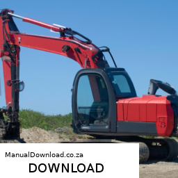
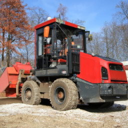
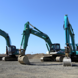
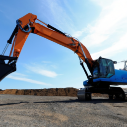
Repairing the shift interlock on a Takeuchi TB125, TB135, or TB145 compact excavator requires following a series of steps in reverse order to ensure proper reassembly and functionality. click here for more details on the download manual…..


    Takeuchi TB153fr Excavator Maintenance Plus Quick Coupler Install… Kinda Performing some maintenance on Takeuchi TB153 excavator, replacing a leaking hydraulic line, and installing a new throttle lever …

    Here’s how to reverse the process:

    ### 6. Reassemble the Operator Controls
    – **Reconnect any electrical connectors** that were unplugged during the process.
    – **Reattach any panels or covers** that were removed to access the shift interlock system.

    ### 5. Install the Shift Interlock Mechanism
    – **Position the new or repaired shift interlock mechanism** back into place.
    – **Secure it with the necessary bolts or screws**, ensuring they are tightened to the manufacturer’s specifications.

    ### 4. Test the Shift Interlock System
    – **Before fully reassembling**, test the interlock to ensure it functions correctly.
    – **Check that the machine only shifts** when it is safe to do so, according to the design.

    ### 3. remove the Old Interlock (if applicable)
    – If you’re replacing the interlock, **remove the faulty interlock mechanism** from its housing.
    – **Disconnect any wiring** or links that are attached to the old interlock.

    ### 2. Gain Access to the Shift Interlock
    – **Remove the operator’s seat or console**, depending on the model, to gain access to the shift interlock mechanism.
    – **Remove any necessary panels or covers** that block access to the shift interlock.

    ### 1. Safety Precautions
    – **Ensure the excavator is turned off** and secured.
    – **Disconnect the battery** to prevent any electrical issues while working on the machine.

    By following these steps in reverse, you can effectively repair the shift interlock on a Takeuchi TB125, TB135, or TB145 compact excavator. Always refer to the manufacturer’s service manual for specific instructions and safety precautions Related to your equipment.
    A cup holder is a practical and often essential component found in various vehicles, including cars, trucks,download Takeuchi TB125 TB135 TB145 Compact Excavator workshop manual 
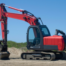
and SUVs. Its primary purpose is to securely hold beverages, allowing drivers and passengers to enjoy drinks without the risk of spills or distractions while on the road. Cup holders come in various designs and configurations, catering to different needs and preferences.

    Typically made from durable plastics or metals, cup holders are designed to accommodate a range of drink containers, including standard-sized cups, bottles, and cans. Many modern vehicles feature molded cup holders that can expand or contract to fit different sizes, ensuring a snug fit for both large coffee cups and standard water bottles. Some cup holders even have additional features, such as insulation to keep beverages hot or cold, or removable inserts for easy cleaning.

    Cup holders are often strategically placed within easy reach of the driver and passengers, usually located in the center console, door panels, or even in the backseat for rear passengers. Their placement is crucial, as it minimizes distractions and enhances passenger comfort. Additionally, with the increasing trend of integrating technology into vehicles, some cup holders now include charging ports or illumination features, making them more functional than ever.

    In summary, the cup holder is a small yet significant component that enhances the driving experience by providing a convenient and secure place for beverages, reflecting the importance of comfort and practicality in modern automotive design.

    Download PC35R-8, PC45R-8 Shop Manual Repair Book #2 –

    australia
    Replacing a transmission torque sensor on a PC35R-8 or PC45R-8 excavator can seem daunting, but with a bit of guidance and some basic tools, you can do it yourself. click here for more details on the download manual…..


      Replacing leaky broken & worn hydraulic hoses on a Komatsu PC45R-8 mini Excavator with locati… I had some leaks on my machine. One was on the main hydraulic arm and there were 2 bad hoses in the hydraulics compartment.

    Here’s a step-by-step guide that breaks it down into simple terms:

    ### Tools and Materials Needed:
    – Wrench set
    – Socket set
    – Screwdriver set
    – Torque sensor replacement part
    – Clean cloth
    – Safety gloves
    – Safety glasses

    ### Steps for Replacing the transmission Torque Sensor:

    1. **Safety First**:
    – Ensure the excavator is turned off, and the key is removed from the ignition.
    – Engage the parking brake and place wheel chocks around the tracks to prevent any movement.

    2. **Locate the Torque Sensor**:
    – The torque sensor is typically located near the transmission. You may need to refer to the manual for the exact location, but it’s usually mounted on the transmission housing.

    3. **Access the Sensor**:
    – Depending on the design of your excavator, you may need to remove some covers or panels to access the torque sensor. Use the appropriate screwdriver or socket to remove these components carefully.

    4. **Disconnect Wiring**:
    – Once you can see the sensor, gently disconnect the electrical connector attached to it. There might be a clip or a tab that you need to press or lift to release the connector. Be careful not to damage any wires.

    5. **Remove the Old Sensor**:
    – Using a wrench or socket, unscrew the bolts or nuts holding the torque sensor in place. Keep these fasteners in a safe spot, as you will need them for the new sensor.
    – Once the bolts are removed, carefully pull the old sensor out. There might be some resistance, but it should come out easily if everything is loose.

    6. **Prepare the New Sensor**:
    – Take your new torque sensor out of the packaging. Before installation, compare it with the old sensor to ensure it’s the correct part.
    – Clean the area where the sensor will be installed to prevent any debris from interfering with the new sensor.

    7. **Install the New Sensor**:
    – Position the new torque sensor in place, making sure it aligns with the mounting holes.
    – Insert the bolts or nuts that you removed earlier and tighten them securely using a wrench or socket. Be sure not to overtighten, as this could damage the sensor or the transmission housing.

    8. **Reconnect the Wiring**:
    – Once the new sensor is securely in place, reconnect the electrical connector. Ensure it clicks into place and is firmly attached.

    9. **Reassemble Any Covers or Panels**:
    – If you removed any covers or panels to access the sensor, replace them now using the appropriate screws or bolts. make sure everything is snug but not overtightened.

    10. **Check Your Work**:
    – Before starting the excavator, double-check that all connections are securedownload PC35R 8 PC45R 8  2 workshop manual and that there are no tools left in the engine compartment.

    11. **Start the Excavator**:
    – Turn the key to start the excavator. Observe the display or any gauges to ensure the torque sensor is functioning correctly. If there are any error messages or warnings, consult the manual or a professional.

    12. **Test the Equipment**:
    – Finally, take the excavator for a short test run to ensure everything is operating smoothly. Pay attention to any unusual sounds or issues.

    ### Conclusion:
    Replacing the transmission torque sensor on a PC35R-8 or PC45R-8 can be a straightforward process if you follow these steps carefully. Always prioritize safety and consult the user manual for specific details related to your model. If you encounter any difficulties or uncertainties, don’t hesitate to seek help from a professional technician.
    A tow strap, also known as a tow rope, is a crucial automotive accessory designed for towing vehicles that have become immobilized or require assistance. Typically constructed from strong, durable materials like nylon or polyester, tow straps are engineered to withstand significant tension and force. Their primary function is to provide a reliable means of pulling a vehicle, whether it is stuck in mud, snow, or has broken down on the road.

    Tow straps come in various lengths and widths, usually ranging from 10 to 30 feet and can support different weight capacities, often marked in terms of the maximum weight they can safely tow. The strap is equipped with reinforced looped ends, allowing for secure attachment to the towing vehicle and the vehicle being towed. Some models also come with hooks or carabiners for added convenience and security during towing operations.

    One of the key advantages of tow straps over traditional chains is their lightweight design, making them easier to handle and store. They also tend to be less prone to causing damage to the vehicles involved, as they provide some degree of elasticity, absorbing shocks during towing. However, it is essential to use tow straps correctly, following best practices and ensuring that both vehicles involved are compatible with the tow strap’s specifications to prevent accidents or damage. Properly utilized, tow straps serve as a valuable tool for emergency roadside assistance and off-road adventures, providing peace of mind for drivers in potentially challenging situations.

    Download Daewoo Doosan S280LC-III Operator’s Manual –

    bookshop
    Replacing the clutch pressure sensor on a Daewoo Doosan S280LC III involves several steps. click here for more details on the download manual…..


      HOW TO: MITSUBISHI PAJERO MONTERO 4X4 MANUAL LOCKING AISIN HUBS INSTALL WHEEL BEARINGS SHOGUN DEL… VERY LONG-WINDED HOW-TO video showing installation of manual locking wheel hubs and wheel bearing service on 4M40 …

      Daewoo excavator 130 for sale call 9196019939 Daewoo excavator 130.

    Here’s a reverse order guide on how to perform the replacement:

    ### 10. Reconnect the Battery
    – Reconnect the negative terminal of the battery to ensure electrical power is restored to the machine.

    ### 9. test the Sensor
    – After installation, start the engine and check for proper operation of the clutch system. Ensure there are no warning lights or error codes related to the clutch pressure sensor.

    ### 8. Secure the Wiring
    – Ensure that any wiring harnesses or connectors that were disconnected or moved during the process are securely fastened and not pinched.

    ### 7. Install the New Sensor
    – Thread the new clutch pressure sensor into its mounting location. Make sure it is properly seated and tightened to the manufacturer’s specifications, typically with a torque wrench.

    ### 6. Connect the Wiring Harness
    – Attach the wiring harness to the new sensor. Ensure a secure connection to prevent any electrical issues.

    ### 5. Remove the old Sensor
    – Carefully disconnect the wiring harness from the old clutch pressure sensor. Then, using the appropriate tools, unscrew and remove the old sensor from its location.

    ### 4. Access the Sensor Location
    – Depending on the machine’s layout, you may need to remove certain panels or covers to gain access to the clutch pressure sensor. This may involve using hand tools to unscrew or unclip components.

    ### 3. Prepare the Area
    – Ensure the area around the sensor is clean and free from debris. This will prevent contamination during the replacement process.

    ### 2. Safety Precautions
    – Before beginning the replacement, ensure the equipment is parked on a stable surface, the engine is off, and the key is removed from the ignition. Engage the parking brake for added safety.

    ### 1. Gather Tools and Replacement Parts
    – Collect the necessary tools (screwdrivers, wrenches, torque wrench) and obtain the correct replacement clutch pressure sensor for the Daewoo Doosan S280LC III.

    By following these steps in reverse order, you can effectively replace the clutch pressure sensor on your Daewoo Doosan S280LC III. Always consult the machine’s service manual for specific detailsdownload Daewoo Doosan S280LC III s workshop manual and torque settings related to your model.
    The instrument cluster, often referred to as the dashboard or gauge cluster, is a critical component of a vehicle’s interior. Located directly in front of the driver, it serves as the primary interface for displaying essential information regarding the car’s performance and status. Typically consisting of a series of gauges and digital displays, the instrument cluster provides real-time information on various aspects of the vehicle, including speed, engine RPM (revolutions per minute), fuel level, and engine temperature.

    Traditionally, instrument clusters have featured analog gauges, such as speedometers and tachometers, which display information through moving needles on dials. However, modern vehicles increasingly utilize digital displays, allowing for greater customization and integration of advanced technologies. Many contemporary instrument clusters incorporate features such as warning lights, trip computers, and even navigation information. Some high-end vehicles offer fully digital instrument clusters, which can be configured to show different layouts and data based on the driver’s preferences or driving conditions.

    Beyond functionality, the design of the instrument cluster plays a crucial role in vehicle ergonomics and aesthetics. It must be easily readable under various lighting conditions and designed to minimize driver distraction. As vehicles evolve with the advent of driver assistance systems and electric vehicles, the instrument cluster continues to adapt, integrating more sophisticated displays and connectivity options to enhance the driving experience. Overall, the instrument cluster is not merely a set of gauges; it is a vital component that enhances safety, usability, and driver engagement.

    Download Case CX250C, CX250C LR Service Manual –

    workshop
    Replacing the transmission output shaft on a Case CX250C or CX250C LR excavator involves several steps, and it is essential to have a good understanding of the machine’s components and systems. click here for more details on the download manual…..


      WRECKING 2014 TOYOTA PRIUS 1.5 AUTOMATIC (C22972) WEBSITE: http://www.jjautoparts.com.au EBAY STORE: http://stores.ebay.com.au/JJ-Parts-Auto CALL: 02-9724-8099 EMAIL: …

      8981518591 Turbo For John Deere 190G 245G; Case CX210C CX250; Hitachi ZX250 ZX290 Isuzu 4HK1X Eng… 26% OFF buy now https://shop.phessio.com/product/8981518591 Model: RHF55V, CIKE, CIHE Part No.: F5BVED-S0029B …

    This task requires proper tools, safety precautions, and a systematic approach. Here’s a detailed guide on how to perform the replacement:

    ### Tools and Equipment Needed:

    1. **Basic Hand Tools:** Wrenches, sockets, screwdrivers, pliers, and hammers.
    2. **Torque Wrench:** For ensuring proper torque specifications are met.
    3. **Pneumatic Tools:** Impact wrench for removing bolts quickly.
    4. **Pullers:** Gear pullers or slide hammers for removing the shaft.
    5. **Alignment Tool:** To ensure proper alignment during reinstallation.
    6. **Jack and Stands:** To lift and secure the excavator safely.
    7. **Cleaning Supplies:** Rags, solvent, and brushes for cleaning.

    ### safety Precautions:

    – Always wear appropriate personal protective equipment (PPE) such as gloves, safety glasses, and steel-toed boots.
    – Ensure the excavator is on a stable surface and properly secured before starting work.
    – Disconnect the battery to prevent electrical accidents.

    ### Components Involved:

    1. **Transmission:** The unit that transmits power from the engine to the output shaft.
    2. **Output Shaft:** The component that transfers power to the final drive.
    3. **Bearings and Seals:** Support and seal the output shaft.
    4. **Coupling or Gear:** Connects the output shaft to the final drive.
    5. **Heavy Duty Gear Oil:** For lubrication.

    ### Step-by-Step Replacement Process:

    #### 1. Preparation

    – **Disconnect the Battery:** Remove negative and positive cables to prevent any electrical issues.
    – **Drain the transmission Oil:** Use a drain pan to collect the oil. locate the drain plug on the transmission and remove it.

    #### 2. Remove the Transmission

    – **Access the Transmission:** Depending on the excavator’s design, you may need to remove panels or covers to access the transmission.
    – **Disconnect Linkages and Wires:** Remove any hydraulic lines, electrical connectors, and shift linkages attached to the transmission.
    – **Unbolt the Transmission:** Using the appropriate sockets, remove the bolts securing the transmission to the chassis and engine. You may need to support the transmission with a jack or hoist.

    #### 3. Remove the Output Shaft

    – **Remove the Coupling/Gear:** If applicable, unbolt and remove the coupling or gear from the output shaft. This may require the use of a puller.
    – **Extract the Output Shaft:** Carefully pull the output shaft out of the transmission. You may need to use a slide hammer or puller if it is stuck. Be gentle to avoid damaging any bearings or seals.

    #### 4. Inspect Components

    – **Check Bearings and Seals:** Inspect the output shaft bearings and seals for wear or damage. replace any defective parts.
    – **Clean the Area:** Thoroughly clean the output shaft housing and surrounding areas to remove dirt and debris.

    #### 5. Install the New Output Shaft

    – **Prepare the New Shaft:** Ensure the new output shaft is clean and lubricated with the appropriate gear oil.
    – **Insert the Output Shaft:** Carefully slide the new output shaft into the transmission, ensuring it aligns correctly with the bearingsdownload Case CX250C CX250C LR workshop manual and seals.
    – **Reattach the Coupling/Gear:** Secure the coupling or gear onto the output shaft, ensuring it is properly aligned and fastened according to manufacturer specifications.

    #### 6. Reinstall the Transmission

    – **Position the Transmission:** Using a jack or hoist, position the transmission back into place.
    – **Bolt the Transmission:** Reinstall the bolts that secure the transmission to the chassis and engine. Use a torque wrench to tighten them to the specified torque settings.
    – **Reconnect Linkages and Wires:** Reattach any hydraulic lines, electrical connectors, and shift linkages that were disconnected.

    #### 7. Refilling transmission Oil

    – **Replace the Drain Plug:** Ensure the drain plug is securely tightened.
    – **Refill with Gear Oil:** Use the specified type and amount of gear oil to refill the transmission. Check the manufacturer’s manual for exact specifications.

    #### 8. Testing

    – **Reconnect the Battery:** Reattach the battery cables.
    – **Start the Engine:** Run the excavator and check for any leaks around the output shaft and transmission.
    – **Test Drive:** Operate the excavator to ensure the transmission is functioning correctly and the output shaft is transmitting power without issues.

    ### Conclusion

    Replacing the transmission output shaft on a Case CX250C or CX250C LR excavator is a complex task that requires careful planning and execution. Always refer to the manufacturer’s service manual for specific torque specifications and detailed diagrams. If you’re unsure about any step, consider consulting a professional technician or mechanic.
    A wheel speed sensor is a crucial component in modern vehicles, playing a vital role in various systems related to vehicle dynamics and safety. Typically found in the braking system, anti-lock braking system (ABS), traction control, and electronic stability control (ESC), the wheel speed sensor monitors the rotational speed of each wheel. This information is essential for the vehicle’s electronic control unit (ECU) to make real-time adjustments to braking and acceleration, enhancing stability and control during driving.

    There are primarily two types of wheel speed sensors: passive and active. Passive sensors generate an electrical signal in response to the magnetic field created by a toothed ring (tone ring) attached to the wheel hub. As the wheel rotates, the teeth of the ring pass by the sensor, producing an alternating current that correlates with the wheel’s speed. Active sensors, on the other hand, use a built-in magnet and send a constant signal to the ECU, which then interprets the data to determine speed.

    The data provided by wheel speed sensors is critical for preventing wheel lock-up during sudden braking, allowing for smoother and safer stops. Additionally, they help detect wheel slip during acceleration, enabling systems to adjust power delivery to maintain traction. Overall, wheel speed sensors are essential for enhancing vehicle safety, stability, and overall driving performance, adapting to various road conditions and driving behaviors.

    Download KOBELCO Mark-8 Series SK350 Excavators Service Repair Workshop Manual –

    workshop manual
    Replacing the clutch release bearing on a KOBELCO Mark 8 SK350 excavator is a task that requires some mechanical understanding, but I’ll break it down into simple steps. click here for more details on the download manual…..


      KIỂM TRA VÀ SỬA LỖI ĐIỆN C023,B013,H093 KOBELCO-8(CHECKING AND REPAIR ERROR CODE B013 ,… KOBELCO-8 ,#ERORRC023 #B013 ,#H093 , #LỖI #C023.

      Kobelco Solenoid Valve YN35V00047F1 for SK mark 8 Kobelco Solenoid Valve assembly YN35V00047F1,Use for 20T-40T Kobelco Excavator SK-8,different solenoid valve is in …

    Remember, safety is the priority, so always wear appropriate personal protective equipment (PPE) and ensure the machine is turned off and secure before starting any work.

    ### Tools and Materials Needed:
    – Wrenches and sockets
    – Screwdrivers
    – Pliers
    – Jack stands
    – New clutch release bearing
    – Grease (if needed)
    – Service manual (for reference)

    ### Steps for clutch Release Bearing Replacement:

    1. **Safety First**:
    – Ensure the excavator is on a flat surface.
    – Turn off the engine and remove the key.
    – Use jack stands to secure the excavator if you need to lift any parts for better access.

    2. **Access the Transmission**:
    – Depending on the excavator’s design, you may need to remove protective covers or panels to access the transmission area.
    – Consult the service manual for specific instructions on removing these components.

    3. **Disconnect the Battery**:
    – Disconnect the negative terminal of the battery to prevent any electrical issues while working.

    4. **Remove the clutch Assembly**:
    – Locate the clutch assembly. You may need to disconnect linkages, cables, or hydraulic lines that are in the way.
    – Using wrenches or sockets, carefully remove the bolts securing the clutch assembly to the transmission. Keep track of where each bolt goes for reassembly.

    5. **Take Out the Old clutch Release Bearing**:
    – Once the clutch assembly is out, you should see the clutch release bearing. It’s usually mounted on a fork that moves it in and out.
    – Carefully slide the old bearing off its mount. If it’s stuck, gently wiggle it or tap it lightly with a soft mallet.

    6. **Install the New clutch Release Bearing**:
    – Take your new clutch release bearing and apply a little grease if the service manual recommends it.
    – Slide the new bearing onto the fork in the same position as the old one. Ensure it fits snugly.

    7. **Reassemble the clutch Assembly**:
    – Place the clutch assembly back into position and secure it with the bolts you removed earlier. Make sure everything is aligned properly.
    – Reconnect any linkages, cables, or hydraulic lines that you disconnected earlier.

    8. **Reconnect the Battery**:
    – Reconnect the negative terminal of the battery.

    9. **Test the Clutch**:
    – Before fully closing everything up, start the excavator to test the clutch operation. Ensure that the release bearing is functioning correctlydownload KOBELCO Mark 8 SK350 Excavators workshop manual and that you can engage and disengage the clutch smoothly.

    10. **Final Checks**:
    – After confirming the operation, reattach any protective covers or panels you removed earlier.
    – Clean up your workspace and ensure all tools are accounted for.

    ### Important Tips:
    – Always refer to the KOBELCO service manual for specific torque settings and detailed procedures, as this can vary by model.
    – If you’re unsure about any step, don’t hesitate to consult a professional mechanic or technician.

    ### Conclusion:
    Replacing the clutch release bearing on your KOBELCO Mark 8 SK350 excavator requires careful attention to detail and safety precautions. By following these steps methodically, you can successfully complete the replacement. Good luck!
    A clutch disc, also known as a clutch plate, is a vital component in a vehicle’s manual transmission system, playing a crucial role in the engagement and disengagement of the engine from the drivetrain. It is situated between the engine’s flywheel and the pressure plate within the clutch assembly. The primary function of the clutch disc is to transmit torque from the engine to the transmission while allowing for smooth gear changes.

    The clutch disc is typically made of a durable friction material on its surface, designed to withstand high levels of heat and friction generated during operation. This friction material is essential for creating the necessary grip between the disc and the flywheel, allowing the engine’s power to be transmitted effectively. When the driver presses the clutch pedal, the pressure plate releases its grip on the clutch disc, allowing it to spin freely and disengage from the flywheel. This action enables the driver to shift gears without grinding or damaging the transmission.

    Over time, clutch discs can wear down due to friction, leading to symptoms such as slipping, difficulty in shifting gears, or a burning smell. Regular inspection and maintenance are crucial to ensure optimal performance and longevity of the clutch system. In summary, the clutch disc is an essential component that facilitates smooth gear transitions and efficient power transfer in manual vehicles, significantly impacting the driving experience.

    Download HYUNDAI R1200LC-9 Crawler Excavator Service Repair Manual –

    australian
    Replacing brake pads on a Hyundai R1200LC-9 Crawler Excavator involves several steps that should be performed in a careful and organized manner. click here for more details on the download manual…..


      Hyundai HX300L demo in quarry

      R1200LC-9A Working in California

    Below, I’ve outlined the procedure in reverse order:

    ### 10. Reassemble the Components
    – **Reinstall any removed components**: Ensure all parts that were taken off during the process are securely reattached.
    – **Torque bolts**: Use a torque wrench to tighten all bolts to the manufacturer’s specifications.

    ### 9. Test the Brakes
    – **Check brake operation**: Before putting the excavator back into operation, test the brakes to ensure they engage and release properly.
    – **Look for leaks**: Inspect for any fluid leaks around the brake components.

    ### 8. Reconnect the Brake Lines
    – **Reconnect hydraulic lines**: If any hydraulic lines were disconnected, make sure they are properly reattached and secure.

    ### 7. Install the New Brake Pads
    – **Position the new pads**: Place the new brake pads into the caliper or designated housing.
    – **Ensure correct alignment**: Make sure the pads are seated correctly against the rotor or drum.

    ### 6. Compress the Caliper Piston
    – **Use a caliper tool**: If applicable, use a brake caliper tool to compress the caliper piston to make space for the new pads.

    ### 5. Remove the Old Brake Pads
    – **Take out the old pads**: Carefully remove the old brake pads from the caliper or housing.
    – **Inspect for wear**: Check the old pads for wear and ensure the rotor or drum is not damaged.

    ### 4. Access the Brake Assembly
    – **Remove wheel or cover**: Depending on the excavator’s design, you may need to remove wheels or protective covers to access the brake assembly.
    – **Unbolt the caliper or brake housing**: Remove any bolts or clips holding the caliper or brake assembly in place.

    ### 3. Prepare the Work Area
    – **Ensure safety**: Park the excavator on a level surface and engage the parking brake. Use wheel chocks for added safety.
    – **Gather tools and materials**: Have all necessary tools (wrenches, sockets, brake cleaner, new brake pads, etc.) and safety equipment ready.

    ### 2. Disconnect the Battery
    – **Turn off the machine**: Ensure the excavator is powered down.
    – **Disconnect the battery**: To prevent any electrical issues, disconnect the battery terminals.

    ### 1. Review the Service Manual
    – **Consult the manual**: Before starting, review the Hyundai R1200LC-9 service manual for specific instructionsdownload HYUNDAI R1200LC 9 Crawler Excavator workshop manual and torque specifications related to brake pad replacement.

    By following these steps in reverse order, you can effectively replace the brake pads on the Hyundai R1200LC-9 Crawler Excavator while ensuring safety and proper functionality. Always refer to the manufacturer’s guidelines for detailed procedures and specifications.
    A jack stand is a vital safety tool used in automotive maintenance and repair, designed to support a vehicle when it has been lifted off the ground. Typically made from sturdy materials such as steel or heavy-duty aluminum, jack stands provide a stable and secure means of holding a vehicle in place after being elevated by a hydraulic jack or floor jack.

    The primary purpose of a jack stand is to prevent a vehicle from accidentally falling while mechanics or DIY enthusiasts work underneath it. This is crucial because working under a raised vehicle poses significant risks, including severe injury or death if the vehicle were to collapse. Jack stands come in various sizes and weight capacities, allowing users to select a suitable option based on the vehicle’s weight and the height required for the job.

    Most jack stands feature a ratchet mechanism that allows for height adjustment, enabling users to achieve the desired lift while ensuring stability. They typically have a wide base for enhanced support and stability, reducing the risk of tipping over. When using jack stands, it is essential to follow safety guidelines, including placing them on solid ground and using them in pairs to evenly distribute the vehicle’s weight. Overall, jack stands are indispensable for safe vehicle maintenance, promoting both efficiency and safety in automotive work.

    Download HITACHI EX200 EX200LC Excavator EQUIPMENT PartsManual –

    do your own repairs
    Cleaning the intake manifold on a Hitachi EX200 or EX200LC excavator is an important maintenance task that helps ensure the engine runs efficiently. click here for more details on the download manual…..


      Cummins Engine All Parts Name & Image Full Details. Cummins Engine Parts Name. Hello Friends, Welcome to my channel ” MACHINE INTRODUCE ” दोस्तों में आप …

      excavator parts name in hindi | jcb excavator parts name parts name | @operatorekta excavator parts name in hind jcb excavator parts name parts name Excavator parts name Excavator parts in hindi Excavator parts …

    Below is a step-by-step guide designed for individuals with little mechanical experience.

    ### Tools and Materials Needed:
    – Safety Gloves and goggles
    – Wrench set
    – Socket set
    – Screwdriver set
    – Clean rags or shop towels
    – Engine cleaner or degreaser
    – Soft brush (like a toothbrush)
    compressed air (optional)

    ### Step-by-Step Guide:

    #### 1. **Safety First**
    – **Turn off the Engine**: Make sure the excavator is turned off and cooled down.
    – **Disconnect the Battery**: Disconnect the negative terminal of the battery to prevent any electrical issues while you work.

    #### 2. **Locate the Intake Manifold**
    – The intake manifold is usually located on the side of the engine. It’s a large metal component that connects to the engine block and has hoses leading to it.

    #### 3. **Remove Obstructions**
    If there are any hoses or components connected to the intake manifold, carefully remove them. Take note of where each hose connects, as you’ll need to put them back later. You can take pictures to help remember.

    #### 4. **Unscrew the Intake Manifold**
    using the wrench or socket set, carefully unscrew the bolts that hold the intake manifold in place. Keep track of the bolts, as you’ll need them to reattach the manifold.

    #### 5. **Take Out the Intake Manifold**
    – Once all the bolts are removed, gently lift the intake manifold off the engine. Be careful not to damage any gaskets (seals) that may be attached.

    #### 6. **Clean the Manifold**
    – **Inspect for Dirt and Debris**: Look for any dirt, carbon build-up, or other debris inside the manifold.
    – **Apply Cleaner**: Spray the engine cleaner or degreaser inside the manifold. Let it sit for a few minutes to break down the grime.
    – **Scrub**: Use the soft brush to scrub the inside of the manifold. Pay attention to any stubborn spots.
    – **Wipe Clean**: Use clean rags or shop towels to wipe out all the residue and cleaner. Make sure it’s clean and dry before reinstalling.

    #### 7. **Clean the Gaskets (if reusable)**
    If the gaskets (seals) on the intake manifold are in good shape and reusable, wipe them down with a clean rag. If they are damaged, you will need to replace them.

    #### 8. **Reinstall the Intake Manifold**
    – Carefully place the intake manifold back onto the engine.
    – Reattach any gaskets you removed (or new ones If needed).
    – Tighten the bolts securely but be careful not to overtightendownload HITACHI EX200 EX200LC Excavator EQUIPMENT PartsManual workshop manual and damage the manifold.

    #### 9. **Reconnect Hoses and Components**
    – Reattach any hoses and components you removed earlier, ensuring they are secured properly.

    #### 10. **Reconnect the Battery**
    – Reconnect the negative terminal of the battery.

    #### 11. **Test the Engine**
    – Start the excavator and let it run for a few minutes. Check for any unusual noises or leaks around the intake manifold.

    ### Conclusion
    Regularly cleaning the intake manifold helps maintain engine performance and prolongs the life of your excavator. If you encounter any issues during the process or feel uncertain, don’t hesitate to consult a professional or refer to the equipment’s service manual. Always prioritize safety and proper handling of tools.
    A radiator hose is a crucial component of a vehicle’s cooling system, responsible for transporting coolant between the engine and the radiator. Typically made from durable rubber or silicone, these hoses are designed to withstand extreme temperatures and pressures generated during engine operation. There are generally two main types of radiator hoses: the upper hose and the lower hose.

    The upper radiator hose connects the engine’s thermostat housing to the radiator, allowing hot coolant to flow from the engine to the radiator, where it cools down before being recirculated back into the engine through the lower hose. The lower hose, on the other hand, carries the cooled coolant back from the radiator to the engine, ensuring that the engine operates within its optimal temperature range.

    Over time, radiator hoses can degrade due to heat, pressure, and exposure to various chemicals. Signs of wear include cracks, bulges, or leaks, which can lead to coolant loss and potential overheating of the engine. Therefore, regular inspection and maintenance of radiator hoses are essential for preventing costly repairs and ensuring the vehicle operates efficiently. In summary, radiator hoses play a vital role in maintaining engine temperature, contributing significantly to overall vehicle performance and longevity.

    Download JCB Mini Excavator 8014 8016 + Engine Workshop Repair Manual –

    diy
    Replacing a tie rod end on a JCB Mini Excavator 8014 or 8016 involves several steps. click here for more details on the download manual…..


      Yella Fella – How to break and fix a JCB 8014 CTS JCB 8014 CTS MY2013 Issues list: Hydraulic fluid leak. Hideous and deafening knocking sound. How to tilt the cab. How I fixed …

      Here’s a reverse order guide to help you understand the process from the end to the beginning:

      ### 6. Reassembly and Final Checks
      – **Reconnect the Battery**: Reconnect the negative terminal of the battery.
      – **Test the Joint**: Move the excavator’s steering to ensure the new tie rod end is functioning properly without any obstructions or unusual noises.
      – **Lower the Equipment**: If elevated, lower the excavator back to the ground.

      ### 5. Installation of New Tie Rod End
      – **Install the New Tie Rod End**: Insert the new tie rod end into the steering linkage. Make sure it is properly aligned.
      – **Secure with Nut**: Use a wrench to tighten the nut to the manufacturer’s specified torque.

      ### 4. Removal of Old Tie Rod End
      – **Remove the Old Tie Rod End**: Use a puller or hammer to detach the old tie rod end from the steering linkage. Be careful not to damage surrounding components.
      – **Inspect for Damage**: Check the steering linkage and surrounding components for any signs of wear or damage.

      ### 3. Preparing for Installation
      – **Lift the Excavator**: Use a jack to lift the excavator if needed, ensuring it is secure with jack stands.
      – **Remove the Wheel (if applicable)**: If the tie rod end is on a wheel steering joint, remove the wheel to gain access.

      ### 2. Tools and components Needed
      – **Gather Tools**: You’ll need a wrench set, socket set, tie rod end puller, torque wrench, and possibly a hammer.
      – **Get the New Tie Rod End**: Ensure you have the correct replacement part specific to the JCB model.

      ### 1. Safety Precautions
      – **Wear Safety Gear**: Ensure you have gloves, safety glasses, and other protective gear.
      – **Park on Level Ground**: Make sure the excavator is parked on level ground and turned off.
      – **Engage Parking Brake**: Engage the parking brake to prevent any movement during the replacement process.

      By following these steps in reverse, you can effectively undersdownload JCB Mini Excavator 8014 8016 + Engine workshop manualtand the tie rod end replacement process for a JCB Mini Excavator 8014 or 8016. Always refer to the specific service manual for detailed instructions and torque specifications.
      A seatbelt retractor is a crucial safety component found in vehicles, designed to manage the seatbelt’s tension and ensure optimal restraint for passengers during a collision or sudden stop. This device is responsible for winding and unwinding the seatbelt webbing, allowing it to extend when the occupant enters the vehicle and retract when not in use. The retractor mechanism is typically housed within a compact casing, often mounted on the vehicle’s floor or side pillar, ensuring that it is easily accessible while remaining out of the way.

      The primary function of the seatbelt retractor is to lock the seatbelt in place during a crash. Most retractors use a combination of a spring mechanism and an inertia-sensitive locking system. When the vehicle experiences rapid deceleration or an abrupt change in direction, the inertia mechanism engages, locking the seatbelt in place to prevent the occupant from moving forward. This locking feature is vital for reducing the risk of injury by keeping the passenger securely in their seat.

      Additionally, modern seatbelt retractors may incorporate advanced features such as pretensioners, which tighten the belt upon impact, further minimizing slack and maximizing the effectiveness of the restraint system. Overall, the seatbelt retractor plays a pivotal role in automotive safety, contributing to the protection of passengers and reducing the severity of injuries in accidents. Its reliable operation is essential for ensuring that seatbelts function as intended, delivering a critical layer of safety in vehicles.

      Download CASE CX800 Crawler Excavator Service Repair Manual –

      do your own repairs
      Replacing the spark plugs on a CASE CX800 Crawler Excavator is an essential maintenance task that helps ensure optimal engine performance. click here for more details on the download manual…..


        CASE CX800 Excavator Review – Conrad 1:50 Mike’s Models Reviews – Case CX800 Excavator Made by Conrad in 1:50 Scale. Please SUBSCRIBE and LIKE our Facebook …

        Excavator reduction gearbex Belparts Focus on excavator hydraulic field for 10 years, We have a professional service team in the field of excavator hydraulics …

      Below is a detailed guide on how to perform this task, including descriptions of the necessary components and tools.

      ### Tools and Materials Needed:
      1. **New Spark Plugs**: Ensure they are the correct type and specifications for the CASE CX800 engine. Check the operator’s manual for part numbers.
      2. **Spark Plug Socket**: A deep socket specifically designed for spark plugs, typically 5/8” or 13/16” in size.
      3. **Ratchet and Extensions**: A ratchet with extensions to reach the spark plugs comfortably.
      4. **Torque Wrench**: To ensure the spark plugs are installed to the manufacturer’s specifications.
      5. **Spark Plug Gap Tool**: To check and adjust the gap on new spark plugs if necessary.
      6. **Anti-seize Compound**: To apply to the threads of the new spark plugs to prevent seizing.
      7. **Dielectric Grease**: For use on the spark plug boots to ensure a good connection and prevent moisture intrusion.
      8. **Safety Gloves**: To protect your hands during the process.
      9. **Safety Glasses**: To protect your eyes from debris.

      ### Step-by-Step Process:

      1. **Preparation**:
      – **Safety First**: Ensure the excavator is parked on a stable, level surface. Engage the parking brake and turn off the engine. Allow the engine to cool down if it has been running.
      – **Disconnect the Battery**: Remove the negative terminal from the battery to prevent any accidental electrical discharge.

      2. **Locate the Spark Plugs**:
      – The spark plugs are typically located on the engine block. Refer to the operator’s manual if you have difficulty locating them. You may need to remove any engine covers or components obstructing access.

      3. **Remove the Spark Plug Wires**:
      – Carefully pull the spark plug boot (the rubber cover over the spark plug) straight off the spark plug. Avoid twisting it to prevent damage. It’s advisable to pull one wire at a time to avoid mixing them up.

      4. **Remove the Old Spark Plugs**:
      – Use the spark plug socket and ratchet to unscrew the old spark plugs. Turn counterclockwise to loosen. If they are stuck, apply penetrating oil and wait a few minutes before trying again.
      – Once loosened, remove the spark plug from the engine.

      5. **Inspect the Old Spark Plugs**:
      – Examine the old spark plugs for wear and deposits. This can provide insight into engine performance issues (e.g., oil fouling, carbon deposits).

      6. **Prepare New Spark Plugs**:
      – Check the gap on the new spark plugs using the spark plug gap tool. Adjust the gap according to the specifications in the operator’s manual.
      – Apply a small amount of anti-seize compound to the threads of the new spark plugs to prevent them from seizing in the future.

      7. **Install New Spark Plugs**:
      – Carefully thread the new spark plugs into the engine by hand to avoid cross-threading. Once hand-tight, use the torque wrench to tighten them to the manufacturer’s specifications (usually listed in the operator’s manual).
      – Avoid over-tightening as this can damage the threads in the engine.

      8. **Reconnect the Spark Plug Wires**:
      – Apply a small amount of dielectric grease inside the spark plug boot before reconnecting. This helps protect against moisturedownload CASE CX800 Crawler Excavator workshop manual and makes it easier to remove the boot in the future.
      – Push the spark plug boot back onto the new spark plug until you hear a click, indicating a secure fit.

      9. **Reconnect the Battery**:
      – Reattach the negative terminal of the battery securely.

      10. **Final Checks**:
      – Ensure all tools and materials are removed from the engine area.
      – Start the engine and allow it to run for a few minutes, checking for any unusual sounds or misfires.

      ### Conclusion
      Replacing spark plugs in the CASE CX800 Crawler Excavator is a straightforward process if you follow these steps carefully. Regular maintenance, including spark plug replacement, can significantly enhance engine performance and longevity. Always consult the operator’s manual for specific information related to your model.
      A crankshaft seal, often referred to as a crankshaft oil seal, is a crucial component in an internal combustion engine. Its primary function is to prevent oil from leaking out of the engine, specifically at the junction where the crankshaft exits the engine block. The crankshaft itself plays a pivotal role in the engine’s operation, converting the linear motion of the pistons into rotational motion that ultimately drives the vehicle’s wheels.

      The crankshaft seal is typically made of rubber or a similar elastomeric material, designed to withstand high pressures and temperatures while maintaining a tight seal. It is strategically positioned in the front and rear of the crankshaft, where it interfaces with the crankshaft pulley at the front and the flywheel or flexplate at the rear.

      Over time, crankshaft seals can wear out due to heat, friction, and exposure to engine oil, leading to leaks. Oil leaks not only result in a loss of engine lubrication, which can cause severe engine damage, but they can also create a messy environment under the vehicle and pose potential fire hazards.

      Replacing a worn or damaged crankshaft seal is essential for maintaining engine integrity and performance. The process typically involves removing components like the timing belt or chain, which can be labor-intensive and require mechanical expertise. Regular maintenance and timely inspections can help identify seal degradation before it leads to more significant issues.

      Download Doosan Daewoo 220LC-V Excavator Repair Service Manual –

      books
      Replacing the brake line on a Doosan Daewoo 220LC V Excavator involves several steps to ensure safety and proper functionality. click here for more details on the download manual…..


        For Doosan Daewoo DB58T DB58 DB58TIS Engine Hitachi EX200 1 EX200 2 EX200 3 Excavator Overhaul Ga… For Doosan Daewoo DB58T DB58 DB58TIS Engine Hitachi EX200-1 EX200-2 EX200-3 Excavator Overhaul Gasket Kit.

        Awesome Restoration Of Excavator Final Drive Assembly // Doosan Final Drive Oil Seal Replacement AwesomeRestorationOfExcavatorFinalDrive Assembly//DoosanFinalDriveOilSealReplacement #excavator #finaldrive …

      Here’s a reverse order guide to help you understand the process:

      ### 8. **Reconnect the Brake System**
      – Reconnect the brake lines to the brake cylinder and any other necessary components, ensuring they are securely fastened.
      – Tighten any fittings to the manufacturer’s specifications using a torque wrench.

      ### 7. **Reinstall Components**
      – Reinstall any components or covers that were removed to access the brake lines.
      ensure all bolts and fasteners are tightened appropriately.

      ### 6. **Bleed the Brake System**
      – Bleed the brake system to remove any air that may have entered during the replacement. This usually involves opening the bleeder valve and pumping the brake pedal until fluid comes out without air bubbles.
      keep an eye on the brake fluid reservoir and top it up as needed to prevent introducing more air.

      ### 5. **Test the Brake Line**
      – Before fully reassembling everything, conduct a test to ensure the new brake line is functioning properly. Activate the brakes to check for any leaks or irregularities.

      ### 4. **Install the New Brake Line**
      – Position the new brake line in place, ensuring it follows the same routing as the old line to avoid any interference with moving parts.
      – Secure the new line with any brackets or clamps that were removed earlier.

      ### 3. **Remove the Old Brake Line**
      Disconnect the old brake line from the brake cylinder and any other connections. Use an appropriate wrench to avoid damaging the fittings.
      – Carefully remove the line, taking care not to spill any brake fluid.

      ### 2. **Prepare the Work Area**
      ensure the excavator is on a stable surface and properly shut down.
      – Gather all necessary tools such as wrenches, a brake line replacement kit,download Doosan Daewoo 220LC V Excavator workshop manual and brake fluid.

      ### 1. **Safety Precautions**
      – Wear gloves and safety glasses to protect yourself from brake fluid and debris.
      – Make sure to relieve any pressure in the brake system by carefully opening the brake fluid reservoir cap before starting work.

      This reverse order guide should help provide a clear understanding of the brake line replacement process on a Doosan Daewoo 220LC V Excavator. Always consult the manufacturer’s service manual for specific instructions and safety guidelines related to your equipment.
      An oil cooler line is a crucial component in an automobile’s lubrication system, designed to help maintain optimal engine temperatures and ensure the efficiency of the engine oil. It serves as a conduit for circulating engine oil from the engine to the oil cooler and back, facilitating effective heat dissipation. By regulating the temperature of the engine oil, the oil cooler line plays a vital role in preventing overheating, which can lead to engine wear, reduced performance, and potential damage.

      Typically made of rubber or metal, oil cooler lines are engineered to withstand high pressures and temperatures, as they transport oil that is vital for lubricating various engine components. The design of these lines includes features such as reinforced walls to prevent bursting and special fittings that allow for secure connections to the engine and oil cooler.

      In many vehicles, especially those with high-performance engines or those used in demanding conditions, the oil cooler line is essential for maintaining engine health. If an oil cooler line develops a leak or becomes damaged, it can lead to a drop in oil pressure, resulting in inadequate lubrication and potential engine failure. Regular inspection and maintenance of the oil cooler line are crucial for ensuring the longevity and performance of the vehicle, making it a key component in automotive engineering.