Download Case 621F 721F Tier 4 Wheel Loader Service Repair Manual –

fix
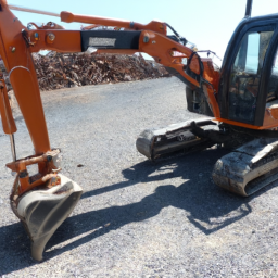
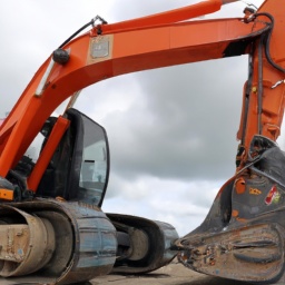
Replacing the gearbox on a Case 621F or 721F Tier 4 Wheel Loader can seem daunting, but with some basic mechanical understanding and careful steps, it can be done. click here for more details on the download manual…..


      CASE 721F – ASCO Equipment CASE 721F Wheel loader feeding and clearing output from a tub grinder at Whittlesey Lanscape Supply in Austin TX. This video …

    Here’s a simplified guide to help you through the process.

    ### Tools and Materials Needed:
    1. **Basic Hand Tools**: Wrenches, sockets, screwdrivers, and pliers.
    2. **Jack and Jack Stands**: To lift the loader safely.
    3. **Gearbox Replacement**: A new or refurbished gearbox.
    4. **Lubricant**: For reassembly.
    5. **Safety Gear**: Gloves, goggles, and steel-toed boots.
    6. **Service Manual**: For specific torque settings and diagrams.

    ### Steps to Replace the Gearbox:

    #### 1. **Preparation**
    – **Safety First**: Make sure the machine is on a flat surface and engage the parking brake. Wear your safety gear.
    – **Disconnect the Battery**: To prevent any electrical issues, disconnect the battery terminals.

    #### 2. **Lift the Loader**
    – Use a jack to lift the front of the wheel loader. Secure it with jack stands to ensure it won’t fall while you’re working.

    #### 3. **Remove the Old Gearbox**
    – **Access the Gearbox**: You might need to remove other components like the engine cover or protective shields to reach the gearbox.
    – **Disconnect Components**: Carefully disconnect any hoses, wires, or linkages connected to the gearbox. Label them if necessary for easier reassembly.
    – **Unbolt the Gearbox**: Use the appropriate tools to remove the bolts holding the gearbox in place. Keep track of the bolts in a container.
    – **Remove the Gearbox**: Once unbolted, gently pull the gearbox out. You may need help for this, as it can be heavy.

    #### 4. **Install the New Gearbox**
    – **Position the New Gearbox**: Carefully lift the new gearbox into place. Make sure it aligns with the mounting points.
    – **Bolt It Down**: Secure the gearbox by tightening the bolts you removed earlier. Refer to the service manual for the correct torque specifications.
    – **Reconnect Components**: Reattach any hoses, wires, or linkages you disconnected earlier.

    #### 5. **Final Checks**
    – **Inspect Everything**: Before lowering the loader, double-check that all connections are secure and there are no leftover parts.
    – **Refill Fluids**: If the gearbox requires lubrication, make sure to refill it as needed.

    #### 6. **Lower the Loader**
    – Carefully remove the jack stands and lower the loader back to the ground.

    #### 7. **Reconnect the Battery**
    – Reconnect the battery terminals, ensuring a secure connection.

    #### 8. **Test the Loader**
    – Start the loaderdownload Case 621F 721F Tier 4 Wheel Loader workshop manual and let it run for a few minutes. Check for any unusual noises or leaks. test the operation of the gearbox by moving the machine forward and backward.

    #### 9. **Final Cleanup**
    – Clean up your workspace, disposing of any old parts and fluids according to local regulations.

    ### Important Tips:
    – **Follow Safety Procedures**: Always prioritize safety when working with heavy machinery.
    – **Consult the Manual**: The service manual will provide specific instructions and torque settings that are crucial for a successful replacement.
    – **Take Your Time**: Don’t rush the process. ensure each step is done correctly to avoid issues later on.

    By following these steps, you should be able to replace the gearbox on a Case 621F or 721F Wheel Loader. If you’re ever unsure about a step, it’s best to consult a professional for assistance.
    A heater hose is a crucial component of a vehicle’s heating and cooling system, designed to facilitate the transfer of hot coolant from the engine to the heater core and back. Typically constructed from durable rubber or silicone, heater hoses are engineered to withstand high temperatures and pressures associated with the engine’s operation. Their primary function is to transport heated coolant, which is generated by the engine during combustion, to the heater core, a small radiator-like component located inside the vehicle’s cabin.

    Once the hot coolant flows into the heater core, it transfers its heat to the air that is blown into the cabin by the vehicle’s heating system. This process warms the interior of the car, providing comfort for passengers, especially in colder weather. After passing through the heater core, the cooled coolant returns to the engine through a return hose, where it is re-heated and cycled again.

    Heater hoses come in various lengths and diameters, tailored to fit specific vehicle models. Over time, they can degrade due to exposure to heat, chemicals, and the elements, leading to leaks or cracks. Regular inspection and maintenance of heater hoses are essential to prevent overheating issues and ensure efficient cabin heating. A malfunctioning heater hose can lead to coolant leaks, which may compromise engine performance and lead to costly repairs if not addressed promptly.

    Download VOLVO L180E Wheel LoaderService Repair Manual –

    shop
    Replacing the transmission filter on a Volvo L180E Wheel Loader involves several steps and requires specific tools and materials. click here for more details on the download manual…..


      volvo l180g high lift cada día que trabajo en esta maquina la encuentro excelente gran fuerza,estabilidad, ligera, confortable,ahorro de combustible …

      Know your machine – Volvo L180H High-Lift – Basic operator training – 4/7 In this video, you will get to know your Volvo L180HHL a bit better. Volvo High-Lifts are equipped with a Mode selector, Automatic …

    Below is a detailed description of the process, including the necessary tools.

    ### Tools and Materials Needed:
    – **Socket set**: A complete set of metric sockets (including extensions) will help remove bolts and nuts on the transmission housing.
    – **Wrenches**: A set of metric wrenches for any areas where sockets cannot fit.
    – **Screwdrivers**: Flathead and Phillips screwdrivers for clamps and securing components.
    – **Pliers**: Needle-nose and regular pliers for hose clamps and tightening or loosening connectors.
    – **Transmission filter**: Ensure you have the correct replacement filter specific to the L180E model.
    – **Gasket or sealant**: If the filter or housing requires a gasket, ensure you have the correct one, or use suitable sealant as per the manufacturer’s specifications.
    – **Oil catch pan**: To collect any fluid that may leak during the filter replacement process.
    – **Shop towels or rags**: For cleaning up spills and wiping down surfaces.
    – **Safety gloves and goggles**: To protect yourself while working.
    – **Torque wrench**: To ensure bolts are tightened to the manufacturer’s specified torque.

    ### Replacement Steps:
    – **Prepare the Work Area**:
    park the wheel loader on a flat, stable surface and engage the parking brake.
    – Ensure the engine is turned off and has cooled down to prevent burns or injuries.

    – **Locate the Transmission Filter**:
    – Identify the location of the transmission filter. It is typically situated on the transmission housing, often near the rear of the machine.

    – **Drain Transmission Fluid**:
    – Position the oil catch pan under the transmission to collect any fluid that drains out.
    If applicable, locate the transmission fluid drain plug and remove it to allow the fluid to fully drain. This step may not be necessary If the filter design allows for a dry change.

    – **Remove the old Filter**:
    – Using the appropriate tools, carefully remove any bolts or clamps securing the transmission filter.
    – Detach the old filter from its mounting location. Be cautious as some fluid may still leak out.
    – Inspect the old filter and surrounding components for any signs of wear or damage.

    – **Install the New Filter**:
    – Take the new transmission filter and, If required, apply a thin layer of transmission fluid to the rubber O-ring on the filter. This helps create a good seal.
    – Position the new filter in place and secure it using the previously removed bolts or clamps.
    If a gasket is required, ensure it is properly seated before tightening.

    – **Reattach the Drain Plug**:
    If the drain plug was removed, clean the threadsdownload VOLVO L180E Wheel Loader workshop manual and reinsert it, tightening to the manufacturer’s specified torque.

    – **Refill Transmission Fluid**:
    – Locate the transmission fluid fill cap, typically found on top of the transmission housing.
    – Use a funnel to pour new transmission fluid into the housing, ensuring you use the recommended type and quantity specified by the manufacturer.

    – **Check for Leaks**:
    – Start the engine and allow it to run for a few minutes.
    – Carefully inspect the filter area and surrounding components for any signs of leaks. If any leaks are present, address them before continuing.

    – **Final Checks**:
    – After confirming there are no leaks, shut down the engine and check the fluid level using the dipstick (if equipped). Add more fluid If necessary to reach the proper level.
    – Clean up any spilled fluid and dispose of the old filter and fluid according to local regulations.

    ### Conclusion:
    Replacing the transmission filter on a Volvo L180E Wheel Loader is a straightforward process when the appropriate tools and steps are followed. Regular maintenance, including filter changes, is essential for the longevity and efficiency of the machine. Always refer to the operator’s manual for specific details and torque specifications Related to your specific model.
    The fan relay is a crucial component in a vehicle’s electrical system, primarily responsible for controlling the operation of the cooling fan or fans in the engine compartment. Its primary function is to act as a switch that enables the fans to turn on or off based on the engine temperature or the demands of the vehicle’s air conditioning system.

    When the engine runs, it generates heat, which can lead to overheating If not properly managed. The fan relay helps regulate this temperature by activating the cooling fans when the engine reaches a certain temperature threshold. It does this by receiving signals from the engine control unit (ECU) or the temperature sensor. Once it receives the appropriate signal, the relay completes the electrical circuit, allowing current to flow to the cooling fan, which then spins to draw air through the radiator and cool the engine.

    Fan relays are typically designed to handle higher electrical loads, as the fans require significant power to operate. They also help to reduce the load on the vehicle’s electrical system by allowing the ECU to control the fans without needing to run higher currents through it directly. In case of a malfunction, a faulty fan relay can lead to overheating issues, as the cooling fans may not operate when needed, resulting in potential engine damage. Therefore, maintaining a functional fan relay is essential for the overall health and performance of the vehicle’s engine.

    Download Hyundai R250LC-3 Crawler Excavator Workshop Service Manual –

    stores
    Replacing the shift cable on a Hyundai R250LC-3 Crawler Excavator involves several steps, and it is important to follow a methodical approach to ensure the job is done correctly. click here for more details on the download manual…..


      Water Tank Radiator ASS'Y 11M9-45010 11M945010 for Hyundai Excavator R55-9 R60-9S R55W-9 R60W… Water Tank Radiator ASS’Y 11M9-45010 11M945010 for Hyundai Excavator R55-9 R60-9S R55W-9 R60W-9S From …

      3863451 CONN-OIL SUCTION for Hyundai excavator 3863451 CONN-OIL SUCTION for Hyundai excavator R140LC-9S, R160LC-9S, R170W-3, R180LC-3, R200NLC-3, R200W-3, …

    Below is a detailed guide outlining the components, tools, and step-by-step instructions for replacing the shift cable.

    ### components Involved
    1. **Shift Cable**: This is the main component that connects the shift lever to the transmission control mechanism.
    2. **Shift Lever**: Located in the operator’s cabin, this lever is used to change the gear.
    3. **Transmission Control Mechanism**: This device receives the input from the shift cable and controls the gear shifting in the transmission.
    4. **Cable Clips/Retainers**: These are used to secure the shift cable in place.
    5. **Adjustment Nut**: This may be used for adjusting the tension in the shift cable.
    6. **Protective Sleeves**: Some cables may have protective sleeves to prevent wear and tear.

    ### Tools Required
    – **Socket Set**: For removing bolts and nuts.
    – **Wrench Set**: For securing and loosening nuts.
    – **Pliers**: For pulling and securing clips.
    – **Screwdrivers**: For removing any covers or retaining screws.
    – **Cable Routing Tool**: Optional, for guiding the new cable into place.
    – **Safety Gear**: Gloves and goggles for personal protection.

    ### Step-by-Step Instructions

    #### Step 1: Safety First
    – Ensure the excavator is on a flat surface.
    – Engage the parking brake.
    – Disconnect the battery to prevent any accidental starts.

    #### Step 2: Access the Shift Cable
    – Open the operator’s cabin or access panel to reach the shift lever.
    – If necessary, remove any covers or panels that obstruct access to the shift cable and lever.

    #### Step 3: Disconnect the Old Shift Cable
    – Locate the connection point where the shift cable attaches to the shift lever.
    – Use a wrench to loosen the adjustment nut (if applicable) and disconnect the cable from the lever.
    – Move to the transmission control mechanism and locate where the other end of the shift cable connects.
    – Again, use a wrench to remove any bolts or clips securing the cable.
    – Carefully pull out the old shift cable from its routing path.

    #### Step 4: Prepare for Installation
    – Inspect the mounting points and ensure there are no obstructions or debris that could interfere with the new installation.
    – Compare the old shift cable with the new one to ensure they are identical in length and fittings.

    #### Step 5: Install the New Shift Cable
    – Route the new shift cable through the same path as the old cable. Use a cable routing tool if necessary for guidance.
    – Secure the cable at the transmission control mechanism first by connecting it to its designated point and tightening any bolts or clips.
    – Move to the shift lever and connect the other end of the cable. adjust the cable length as needed using the adjustment nut.
    – Ensure that the cable is not too loose or too tight.

    #### Step 6: Test the Installation
    – Before reassembling any covers or panels, test the shift lever by moving it through its range of motion.
    – Check that the cable moves smoothly without any binding or excessive slack.
    – If the cable does not operate smoothly, recheck the routingdownload Hyundai R250LC 3 Crawler Excavator workshop manual and adjustments.

    #### Step 7: Secure Everything
    – Once satisfied that the shift cable is functioning correctly, secure any cable clips or retainers.
    – Replace any covers or panels that were removed during the process.
    – Reconnect the battery.

    #### Step 8: Final Testing
    – Start the excavator and test the shift lever in various gears to ensure the shift cable is correctly installed and operating as intended.

    ### Conclusion
    Replacing the shift cable on a Hyundai R250LC-3 Crawler Excavator requires careful attention to detail and methodical execution. By following these steps, you can successfully replace the shift cable and restore the proper functioning of the gear-shifting mechanism. Always refer to the manufacturer’s service manual for specific details related to your model, as there may be slight variations in the process or components.
    Polish, in the context of Automotive care, refers to a type of product used to enhance and maintain the appearance of a vehicle’s exterior surfaces. Specifically, car polish is designed to improve the shine and luster of the paint while also providing a level of protection against environmental factors. It typically contains fine abrasives that help to remove minor imperfections such as swirl marks, light scratches, and oxidation, thereby restoring the car’s original finish.

    The process of polishing a car usually involves applying the polish using a soft cloth or a polishing machine, working it into the surface in circular motions. As the polish is worked into the paint, the abrasives gently cut into the clear coat, smoothing out imperfections and allowing the underlying color to shine through more vividly. This not only enhances the aesthetic appeal of the vehicle but can also contribute to its resale value by maintaining a well-kept appearance.

    In addition to aesthetic benefits, many modern polishes also contain protective agents, such as waxes or sealants, that form a barrier against UV rays, dirt, and moisture, which can lead to fading and deterioration over time. Regular use of polish, combined with proper washing and waxing, can help prolong the life of a vehicle’s paint job, ensuring it looks its best for years to come.

    Download Model 310G Backhoe Loader Operations and Diagnostics –

    fix
    Sure! click here for more details on the download manual…..


      How to Operate a Backhoe | Tractor Loader Backhoe Training BackhoeLoader #TractorLoaderBackhoe #JohnDeere310 How to Operate a Backhoe Loader – using the John Deere 310 for this …

      How to Use a Backhoe Transmission How to Use a Backhoe Transmission. Part of the series: How to Operate a Backhoe. Backhoes have a four-speed transmission …

    A coolant flush is an important maintenance task for keeping your 310G Backhoe Loader’s engine running smoothly. It helps remove old coolant and any contaminants that may have built up over time. Here’s a step-by-step guide on how to perform a coolant flush in simple terms:

    ### Tools and Materials Needed:
    1. **Coolant flush kit** (optional, but helpful)
    2. **Fresh coolant** (check your owner’s manual for the right type)
    3. **Water** (distilled is best)
    4. **Wrench or socket set** (for removing hoses)
    5. **Drain pan** (to catch old coolant)
    6. **Funnel**
    7. **Safety goggles and gloves** (for protection)

    ### Steps to Perform a Coolant Flush:

    1. **Safety First**: Make sure your backhoe is turned off, parked on a flat surface, and the engine is cool. Wear safety goggles and gloves to protect yourself.

    2. **Locate the Radiator**: Open the hood of your backhoe and find the radiator. This is where the coolant is stored.

    3. **Drain the Old Coolant**:
    – Place the drain pan under the radiator.
    – Look for the drain valve at the bottom of the radiator or remove the lower radiator hose with your wrench. Be careful, as old coolant can be hot if the engine was recently running.
    – Allow the old coolant to completely drain into the pan.

    4. **Flush the System**:
    – If you have a coolant flush kit, you can use it according to the instructions. If not, you can flush the system with water.
    – Close the drain valve or reattach the lower hose.
    – Fill the radiator with water using a funnel. This helps rinse out any remaining old coolant and debris.
    – Start the engine and let it run for about 10-15 minutes. This allows the water to circulate through the system.
    – Turn off the engine and let it cool down. Then, drain the water just like you did with the old coolant.

    5. **Add New Coolant**:
    – After draining the water, make sure the drain valve is closed or the hose is reattached.
    – Use the funnel to fill the radiator with fresh coolant. Check your owner’s manual for the correct mixture of coolant and water, as some coolants come pre-mixed.
    – Fill until the coolant reaches the recommended level.

    6. **Bleed the System** (if necessary):
    – Some systems may have a bleed valve to remove air pockets. If your 310G has one, open it while filling to let air escape.
    – Once coolant begins to flow out of the bleed valve, close it.

    7. **Check Levels**: Start the engine again and let it run for a few minutes. Check the coolant level and add more if necessary.

    8. **Dispose of Old Coolant Properly**: Never pour old coolant down the drain or on the ground. Take it to a recycling center or a place that accepts hazardous waste.

    9. **Final Check**: After everything is done, check for leaks around hosesdownload 310G Backhoe Loader Operations s workshop manual and connections. Make sure everything is secure.

    ### Conclusion:
    Congratulations! You’ve successfully flushed and replaced the coolant in your 310G Backhoe Loader. Regular maintenance like this helps ensure your machine runs efficiently and lasts longer. If you have any doubts or feel uncomfortable at any point, don’t hesitate to consult a professional or refer to the owner’s manual for more detailed instructions.
    A tire inflator is a compact and indispensable device designed to inflate vehicle tires, ensuring they maintain optimal pressure for safe and efficient driving. Tire pressure is critical for vehicle performance, fuel efficiency, and overall safety; under-inflated tires can lead to increased wear, reduced traction, and even blowouts. Tire inflators come in various forms, including manual pumps, electric inflators, and Portable air compressors, catering to different user preferences and needs.

    Manual tire inflators typically require physical effort to pump air into the tire, making them ideal for emergency situations or for those who prefer a hands-on approach. Electric tire inflators, on the other hand, are powered by a vehicle’s battery or a standard electrical outlet, allowing for quick and effortless inflation. Many modern electric inflators feature digital gauges that provide accurate pressure readings, automatic shut-off functions that stop inflation once the desired pressure is reached, and built-in lights for nighttime use.

    Portable tire inflators are particularly popular among drivers; they are lightweight and easy to store in a trunk, ready for use whenever needed. Some models even come with adapters to inflate sports equipment or inflatable toys, making them versatile tools for both automotive and recreational applications. Overall, a tire inflator is a practical investment for any vehicle owner, promoting safety and convenience on the road.

    Download Doosan Daewoo DX30Z Track Excavator Service Manual –

    owners manual
    Repairing the gear shift linkage on a Doosan Daewoo DX30Z Track Excavator involves several steps. click here for more details on the download manual…..


      Daewoo Doosan Final Drive Motors – Excavator Travel Traction Motors http://www.finaldrivemotors.com/Daewoo-Travel-Motors-s/114.htm Daewoo Doosan Travel Motors – Daewoo Doosan Final Drive …

    Here’s a reverse order breakdown of the process:

    ### 6. Reassemble the Excavator
    – **Reattach any covers or panels** that were removed to access the gear shift linkage.
    – **Reconnect the battery** and ensure all electrical connections are secure.
    – **Lower the excavator to the ground** and perform a final inspection to ensure everything is in place.

    ### 5. Test the Gear Shift Mechanism
    – **Start the excavator** and test the gear shift to ensure it operates smoothly.
    – **Check for any unusual noises** or resistance while shifting gears.
    – If everything functions correctly, the repair is successful.

    ### 4. Install the New or Repaired Linkage
    – **Attach the new or repaired gear shift linkage** to the lever and the transmission.
    ensure all bolts and fasteners are tightened to the manufacturer’s specifications.
    – **Check alignment** to make sure the linkage is properly positioned.

    ### 3. Remove Defective Linkage
    – **Disconnect the existing gear shift linkage** from the gear shift lever and the transmission.
    – Take Note of how the linkage is connected for accurate reassembly.
    – If applicable, **remove any retaining clips** or bolts that hold the linkage in place.

    ### 2. Inspect and Prepare
    – **Inspect the gear shift linkage** for wear, damage, or misalignment. This may involve cleaning the area and checking for any broken components.
    – If the linkage is damaged, determine whether it can be repaired or needs to be replaced.

    ### 1. Safety Precautions
    – **Ensure the excavator is on a stable, level surface** and engage the parking brake.
    – **Disconnect the battery** to prevent any electrical issues while working on the machine.
    – Wear appropriate **personal protective equipment (PPE)** such as glovesdownload Doosan Daewoo DX30Z Track Excavator workshop manual and safety glasses.

    By following these steps in reverse order, you can effectively repair the gear shift linkage on a Doosan Daewoo DX30Z Track Excavator. Always refer to the specific service manual for detailed instructions and safety guidelines.
    The side mirror, also known as a wing mirror or door mirror, is an essential component of a vehicle that plays a crucial role in ensuring safety and enhancing visibility while driving. Typically mounted on the outer edges of the vehicle, side mirrors are designed to provide the driver with a clear view of the areas adjacent to and behind the vehicle, which are often blind spots that are not visible through the rearview mirror.

    Side mirrors come in various designs and features, including manual and power-adjustable types. Power-adjustable mirrors allow drivers to change the angle of the mirror using controls inside the vehicle, enhancing convenience and safety. Additionally, many modern vehicles are equipped with heated side mirrors to prevent fogging and ice accumulation in colder climates, thus maintaining visibility in adverse weather conditions.

    Some advanced side mirrors include built-in turn signal indicators, which enhance visibility for other drivers and pedestrians by signaling lane changes or turns. Additionally, many vehicles now feature blind-spot monitoring systems that utilize sensors to alert drivers of vehicles in their blind spots, further increasing safety.

    Side mirrors are typically constructed from durable materials, such as plastic and glass, designed to withstand various weather conditions and minor impacts. They are also subject to strict regulations regarding size, placement, and reflectivity to ensure they meet safety standards. Overall, side mirrors are vital for safe driving, providing essential information that helps drivers make informed decisions on the road.

    Download HYUNDAI Crawler Excavator R300LC-7 Service Manual –

    fix
    Certainly! click here for more details on the download manual…..


      Vauxhall Meriva MPV review – CarBuyer Vauxhall Meriva MPV 2014 review: http://bit.ly/1hsu2al Subscribe to the Carbuyer YouTube channel: http://bit.ly/17k4fct Subscribe …

      Here’s a detailed guide on how to replace the radiator on a Hyundai Crawler Excavator R300LC-7, including descriptions of the tools you may need.

      ### Tools Required:
      – **Wrench Set**: A set of metric wrenches for loosening and tightening bolts and nuts.
      – **Socket Set**: A ratchet and socket set, preferably metric, for accessing tighter spaces.
      – **Pliers**: Adjustable or locking pliers for handling hoses and clips securely.
      – **Flathead and Phillips Screwdrivers**: For removing any screws that may hold panels or components in place.
      – **Radiator Hose Clamp Tool**: This tool makes it easier to remove and install hose clamps without damaging the hoses or clamps.
      – **Coolant Drain Pan**: To catch any coolant that spills when removing the radiator.
      – **Shop Towels or Rags**: For cleaning up spills and wiping down components.
      – **Torque Wrench**: To ensure that bolts are tightened to the manufacturer’s specified torque settings during reassembly.
      – **Safety Gear**: Gloves, goggles, and protective clothing to ensure safety during the process.

      ### Replacement Process:
      – **Preparation**:
      – Ensure the excavator is parked on a flat, stable surface.
      – Turn off the Engine and allow it to cool completely to avoid burns from hot components.

      – **Drain Coolant**:
      – Locate the drain valve on the bottom of the radiator.
      – Place the coolant drain pan beneath the valve and open it to drain the coolant.
      – Once drained, close the valve and dispose of the coolant properly.

      – **Remove Hoses**:
      – Identify and carefully remove the upper and lower radiator hoses using the radiator hose clamp tool or pliers.
      – Slide the clamps away from the hose ends and gently twist and pull the hoses off.

      – **Disconnect Electrical Connections**:
      – Identify any electrical sensors or fans connected to the radiator.
      – Carefully disconnect these connections, taking note of where each connection goes for easier reassembly.

      – **Unbolt Radiator**:
      – Use the wrench or socket set to remove bolts securing the radiator to the mounting brackets.
      – Be cautious of any additional brackets or supports that may need to be removed.

      – **Remove Radiator**:
      – After all connections and bolts are removed, carefully lift the radiator out of its compartment.
      – It may be helpful to have an assistant to help maneuver the radiator out to avoid damage.

      – **Inspect and Clean**:
      – Inspect the radiator mounting area for any debris or old sealant that may need to be cleaned.
      – Ensure that the new radiator fits properly in the space provided.

      – **Install New Radiator**:
      – Carefully position the new radiator in place, aligning it with the mounting brackets.
      – Reinstall and tighten the mounting bolts securely using the wrench or socket set.

      – **Reconnect Hoses**:
      – Reattach the upper and lower radiator hoses, ensuring they are seated properly.
      – Slide the clamps back into position and tighten them securely to prevent leaks.

      – **Reconnect Electrical Connections**:
      – Reconnect any electrical sensors, fans, or other components that were disconnected earlier, ensuring that each connection is secure.

      – **Refill Coolant**:
      – Open the radiator capdownload HYUNDAI Crawler Excavator R300LC 7 workshop manual and refill with the appropriate type and mixture of coolant.
      – Keep an eye on the overflow tank to ensure it is filled to the recommended level.

      – **Check for Leaks**:
      – Start the Engine and let it run for a few minutes while checking for any leaks around the hoses, clamps, and radiator.
      – Monitor the temperature gauge to ensure the system is functioning properly.

      – **Final Inspection**:
      – After confirming there are no leaks and the system is operating normally, double-check that all tools and materials have been removed from the work area.
      – Close the hood or access panels securely.

      – **Dispose of Old Radiator and Coolant**:
      – Properly dispose of the old radiator and any used coolant according to local regulations.

      ### Additional Tips:
      – Always consult the excavator’s service manual for specific instructions and torque specifications as they can vary by model.
      – If unsure about any step, consider consulting a professional mechanic to avoid damage to the machinery or personal injury.
      A blow-off valve (BOV) is a crucial component in turbocharged and supercharged engines, specifically designed to manage boost pressure and enhance Engine performance. Its primary function is to release excess pressure from the intake manifold when the throttle is closed, such as during gear shifts or rapid deceleration. When a driver suddenly removes their foot from the accelerator, the airflow intended for the Engine is abruptly cut off, causing a buildup of pressure in the intake system. If this pressure is not released, it can lead to compressor surge, which may damage the turbocharger and reduce its efficiency.

      The blow-off valve operates by opening to vent the excess pressure to the atmosphere or recirculating it back into the intake system, depending on the type of BOV used. There are two main types: atmospheric and recirculating. Atmospheric BOVs release the pressure into the environment, creating a distinctive “whoosh” sound that many car enthusiasts appreciate. In contrast, recirculating BOVs direct the vented air back into the intake before the turbocharger, helping maintain the boost pressure within the system and improving Engine response.

      In addition to protecting the turbocharger, the blow-off valve can also enhance Engine performance by ensuring smoother airflow, reducing turbo lag, and maintaining optimal boost levels. Overall, the BOV is an essential piece of hardware in performance tuning, contributing to both the longevity of the Engine components and the driving experience.

      Download JCB 406, 409 Wheel Loading Shovel Service Repair Manual –

      buy
      Adjusting the gear ratio on a JCB 406 or 409 Wheel Loading Shovel is a complex process that involves several steps and requires specialized tools and knowledge. click here for more details on the download manual…..


        How to operate your JCB Compact Wheel Loader For more information please follow the link below: https://www.jcb.com/en-gb/products/wheel-loaders Get to know your compact …

        2000 JCB 409B wheel loader for sale at auction | bidding closes May 7, 2019 View details and pictures — and place your bid at …

      Here’s a detailed breakdown of the tools needed and the process involved:

      ### Tools Required:
      – **Torque Wrench**:
      – Used to apply a specific amount of torque to fasteners, ensuring they are tightened to the manufacturer’s specifications.

      – **Socket Set**:
      – A variety of sockets (including deep sockets) to fit different bolt sizes on the wheel loader. Ensures that you can access and remove the necessary components.

      – **Wrenches**:
      – Adjustable and fixed wrenches to handle various nuts and bolts that may not be accessible with sockets.

      – **Pliers**:
      – For gripping, twisting, and cutting any wiring or small components as needed during adjustment.

      – **Screwdrivers**:
      – Both flathead and Phillips to remove or adjust any covers or components that may obstruct access to the gear components.

      – **Jack and Stands**:
      – To safely lift and secure the wheel loader before beginning work on the undercarriage.

      – **Oil Drain Pan**:
      – For catching any fluids that may need to be drained during the adjustment process.

      – **Measuring Tools**:
      – Calipers or a micrometer to measure gear components for precision adjustments.

      – **Service Manual**:
      – The vehicle’s specific manual provides diagrams and specifications for gear ratios and adjustment procedures.

      ### Adjustment Process:
      – **Safety First**:
      – Engage the parking brake and ensure the machine is on a flat surface. Use wheel chocks for additional safety. Wear protective gear including gloves and safety glasses.

      – **Prepare the Machine**:
      – Use a jack to lift the front of the loader. Secure it with jack stands to prevent it from falling during the adjustment.

      – **Drain Fluids**:
      – If necessary, drain the transmission or differential fluid into an oil drain pan to prevent spills and make it easier to access the components.

      – **Remove Covers**:
      – Use screwdrivers and wrenches to remove any covers or shields that protect the gear assembly. This may include side panels or undercarriage covers.

      – **Inspect current Gear Ratio**:
      – Before making adjustments, measure the current gear ratio by checking the size of the gear teeth and their arrangement. compare these measurements with those provided in the service manual.

      – **Adjust Gear Components**:
      – Depending on the design, you might need to replace gears or adjust the alignment of the existing gears. This could involve loosening bolts with a torque wrench or socket and repositioning gears according to the desired ratio.

      – **Reassemble Components**:
      – Once adjustments are made, carefully reassemble any removed components. Use the torque wrench to ensure bolts are tightened to the manufacturer’s specifications.

      – **Refill Fluids**:
      – Refill the transmission or differential with the appropriate typedownload JCB 406 409 Wheel Loading Shovel workshop manual and amount of fluid, as specified in the service manual.

      – **Test the Adjustment**:
      – Start the machine and conduct a test run. Pay attention to how the machine operates under load to ensure the new gear ratio is functioning as intended.

      – **Final Inspection**:
      – After testing, inspect all components for any signs of leaks or abnormal wear. Ensure all tools are removed from the work area and that the machine is in a safe, operable condition.

      ### Conclusion:
      Adjusting the gear ratio on a JCB 406 or 409 Wheel Loading Shovel requires careful attention to detail, the right tools, and a thorough understanding of the machinery. always refer to the manufacturer’s service manual for specific instructions and safety precautions. If uncertain, it’s advisable to consult with a professional technician.
      The emission control valve is a critical component of a vehicle’s emission control system, which is designed to reduce the release of harmful pollutants into the atmosphere. This valve plays a significant role in managing the flow of gases and vapors from the fuel system and the engine, ensuring that emissions comply with regulatory standards.

      Typically found in systems such as the Evaporative Emission Control System (EVAP), the emission control valve helps prevent the escape of fuel vapors from the fuel tank into the atmosphere. It operates by controlling the flow of these vapors to the engine, where they can be burned during the combustion process instead of being released into the environment. This not only helps reduce hydrocarbon emissions but also improves fuel efficiency.

      The emission control valve can be electronically or mechanically operated. In modern vehicles, it is often controlled by the engine control unit (ECU), which monitors various parameters such as engine temperature and pressure to optimize performance. When the engine is running, the valve opens and closes at specific intervals, allowing for the effective recycling of fuel vapors and maintaining optimal air-fuel ratios.

      Failure of the emission control valve can lead to increased emissions, reduced engine performance, and can trigger warning lights on the dashboard. Regular maintenance and timely replacement of a faulty valve are essential for ensuring compliance with environmental regulations and for the overall health of the vehicle’s engine.

      Download New Holland 900W Operators Manual –

      bookshop
      Replacing the valve body on a Holland 900W s involves several steps that should be followed carefully to ensure proper installation and functionality. click here for more details on the download manual…..


        Mantenimiento a Generadores: Verificar el Aceite

        The Truth about FAT Tire Ebikes: Sidestep the Bullsh💩 https://tailhappytv.com click here to see my favorite ebikes ⚡️ The pitfalls and deception to look out for when buying a 750w …

      Here’s a reverse order outline of the process:

      ### 8. Reassemble the Transmission
      – **Reconnect Electrical Connections**: Reattach any electrical connectors that were disconnected during the removal process.
      – **Reinstall the Transmission Pan**: Place a new gasket on the pan (if applicable) and bolt it back onto the transmission securely.
      – **Fill Transmission Fluid**: Refill the transmission with the appropriate type and amount of fluid through the dipstick tube.

      ### 7. Install the New Valve Body
      – **Position the New Valve Body**: Carefully align the new valve body with the transmission casing and gently lower it into place.
      – **Secure the Valve Body**: Tighten all bolts to the manufacturer’s specifications to ensure a secure fit.

      ### 6. Remove the Old Valve Body
      – **Disconnect Any Remaining Connections**: Ensure all hoses and electrical connectors are fully detached.
      – **Unscrew the Bolts**: Remove all bolts securing the old valve body to the transmission.
      – **Lift Out the Valve Body**: Carefully lift the old valve body out of the transmission casing.

      ### 5. Prepare for Removal
      – **Drain Transmission Fluid**: Place a drain pan underneath and remove the drain plug or the transmission pan to allow fluid to drain out.
      – **Disconnect the Battery**: Disconnect the negative terminal of the battery to prevent any electrical issues.

      ### 4. Access the Valve Body
      – **Remove the Transmission Pan**: Unscrew and take off the transmission pan to expose the valve body.
      – **Remove Any Obstructions**: Take off any components or brackets that might obstruct access to the valve body.

      ### 3. Safety Precautions
      – **Gather Tools and Parts**: Collect necessary tools (socket set, torque wrench, etc.) and the new valve body.
      – **Read the Service Manual**: Familiarize yourself with the specific instructions and torque specifications for your model.

      ### 2. Prepare the Workspace
      – **Ensure a clean Area**: Work in a clean, organized space to avoid contamination.
      – **Use Proper Safety Gear**: Wear gloves and safety glasses to protect yourself during the replacement process.

      ### 1. Assess the Situation
      – **Diagnose the Issue**: Confirm that the valve body is indeed the problem by checking for symptoms like slipping, harsh shifting, or fluid leaks.

      ### Conclusion
      Following these steps in reverse order can help you undersdownload Holland 900W s workshop manualtand the valve body replacement process on a Holland 900W s. Always refer to the specific service manual for detailed instructions and specifications related to your model for the best results. If you’re not experienced with auto repairs, consider consulting a professional mechanic.
      A bumper is a crucial component of a vehicle’s structure, typically located at both the front and rear ends. Its primary function is to absorb impact during low-speed collisions, thereby protecting the more delicate parts of the vehicle, such as the engine, transmission, and other vital systems. Bumpers are designed to minimize damage to both the vehicle itself and any other objects or vehicles it may come into contact with.

      Modern bumpers are usually constructed from a combination of materials, including plastic, rubber, and metal. This blend allows for a lightweight yet durable structure that can absorb energy during an impact. Many bumpers also incorporate energy-absorbing elements, such as foam or crumple zones, which further enhance their ability to mitigate damage. In addition to their protective role, bumpers often house various features, including sensors, lights, and towing attachments.

      Moreover, bumpers play a significant role in a vehicle’s aesthetics and aerodynamics. Manufacturers often design them to align with the overall style of the vehicle, enhancing its visual appeal. In terms of regulations, bumpers must meet specific safety standards set by government agencies, ensuring they provide adequate protection in the event of a collision. Overall, bumpers are integral to a vehicle’s safety, functionality, and design, serving as the first line of defense in automotive safety.

      Download New Holland LS190 Skid Steer Loader Operators Owners Maintenance Manual –

      discount
      Overhauling the gear set on a Holland LS190 Skid Steer Loader can be a complex task, especially for someone with little mechanical experience. click here for more details on the download manual…..


        New Holland LS190 SkidSteer Operation Video Video showing the operation of the New Holland Skid Steer.

        New holland ls190 skid steer For sale.

      However, I’ll break it down into simpler steps, explaining the process in a way that’s easier to understand. Before you start, ensure you have the right tools, safety equipment, and a service manual for reference.

      ### Tools and Materials Needed:
      1. **Basic Hand Tools**: Wrenches, sockets, screwdrivers, pliers, etc.
      2. **Torque Wrench**: To ensure bolts are tightened to the manufacturer’s specifications.
      3. **Pry Bar**: For removing stubborn parts.
      4. **Gear Oil**: To refill the gear set after overhaul.
      5. **Cleaning Supplies**: Rags, brushes, and degreasers.
      6. **Replacement Parts**: Gaskets, seals, bearings, and any worn gear components.

      ### Safety Precautions:
      – **Wear Safety Gear**: Gloves, safety glasses, and steel-toed boots.
      – **Work in a Well-Ventilated Area**: Preferably outdoors or in a garage with good airflow.
      – **Disconnect the Battery**: To prevent accidental starts.

      ### Step-by-Step Overhaul Process:

      1. **Preparation**:
      – **Read the Manual**: Familiarize yourself with the machine and specific gear set components.
      – **Gather Tools**: Ensure you have everything ready before starting.

      2. **Drain the Gear Oil**:
      – **Locate the Drain Plug**: This is usually at the bottom of the gear case.
      – **Place a Container**: Position a container to catch the old oil as you remove the plug.
      – **Remove the Plug**: Allow the oil to drain completely.

      3. **Remove the Gear Set**:
      – **Access the Gear Set**: This may involve removing panels or covers. Use your manual to identify how to access the gear set.
      – **Disconnect Components**: Carefully disconnect any components that are in the way (like drive shafts or other attachments).
      – **Unbolt the Gear Set**: Use the appropriate socket to remove the bolts holding the gear set in place. Keep track of where each bolt goes.

      4. **Inspect and Clean**:
      – **Check for Wear**: Look for any worn gears, bearings, or seals. If they are damaged, they will need to be replaced.
      – **Clean Surfaces**: Use a degreaser and rags to clean the gear housing and any parts you will be reusing.

      5. **Replace Worn Parts**:
      – **Install New Gears/Seals**: Replace any worn components with new parts. Make sure they are fitted correctly.
      – **Use Gasket Sealant**: If applicable, apply gasket sealant to ensure a good seal when reassembling.

      6. **Reassemble the Gear Set**:
      – **Position the Gear Set**: Carefully place the gear set back into the housing.
      – **Secure with Bolts**: Reinstall and tighten all bolts to the specified torque in the manual.

      7. **Refill with Gear Oil**:
      – **Locate the Fill Plug**: find the fill plug on the gear case.
      – **Pour in New Gear Oil**: Using a funnel, fill the case with new gear oil until it reaches the recommended level. Consult your manual for the specific typedownload Holland LS190 Skid Steer Loader s workshop manual and amount of oil.

      8. **Final Checks**:
      – **Inspect Everything**: Double-check all connections, bolts, and seals to ensure everything is secure.
      – **Reconnect the Battery**: If you disconnected it earlier.

      9. **Test the Loader**:
      – **Start the Loader**: Turn on the skid steer and let it run for a few minutes.
      – **Check for Leaks**: Look underneath for any signs of leaking oil and listen for unusual noises.

      ### Conclusion
      Overhauling the gear set on a Holland LS190 Skid Steer Loader is a detailed process that requires careful attention to detail. If at any point you feel unsure, it’s wise to consult a professional mechanic or technician. Always refer to the service manual for specific instructions and specifications related to your machine. Good luck!
      The windshield, also known as the windscreen in some regions, is a crucial component of a vehicle that serves multiple functions, primarily providing visibility and protection for the driver and passengers. Located at the front of the car, the windshield is made from laminated safety glass, which consists of two layers of glass with a layer of polyvinyl butyral (PVB) sandwiched in between. This construction not only enhances the strength of the glass but also prevents shattering upon impact, thereby reducing the risk of injury from flying glass shards in the event of an accident.

      Beyond its protective role, the windshield contributes to the overall structural integrity of the vehicle. It aids in maintaining the shape of the car’s cabin and plays a vital role in the deployment of airbags during collisions. The design of modern windshields often incorporates features such as tinting for glare reduction, integrated heating elements to prevent frost and ice accumulation, and even advanced technologies like heads-up displays and sensors for advanced driver-assistance systems (ADAS).

      Additionally, windshields are designed to improve aerodynamics, reducing drag and contributing to fuel efficiency. Regular maintenance, including the prompt repair of chips and cracks, is essential for ensuring optimal visibility and safety. Therefore, the windshield is not just a transparent barrier; it is an integral element of automotive engineering that enhances both safety and performance.

      Download New Holland CE LB110.B, LB115.B, LB75.B, LB90.B Operators Manual –

      bookshop
      Replacing the trailing arm on a Holland CE LB110.B, LB115.B, LB75.B, or LB90.B involves several steps. click here for more details on the download manual…..


        2001 NEW HOLLAND LB90 For Sale http://http://www.machinerytrader.com/listingsdetail/detail.aspx?OHID=9889133 Title: 2001 NEW HOLLAND LB90 For Sale …

      Here’s a reverse order breakdown of the process:

      ### 7. **Reassemble and Tighten Components:**
      – Reinstall any removed components such as the wheel, brake drum, and hub.
      – Tighten the wheel lug nuts to the manufacturer’s specified torque.
      – Reattach any other parts that were removed during the process, ensuring everything is secure.

      ### 6. **Lower the Equipment:**
      – Carefully lower the machine back to the ground using the hydraulic system or jack.
      – Remove any jack stands or supports used for safety.

      ### 5. **Install the New Trailing Arm:**
      – Position the new trailing arm in place, aligning it with the mounting points.
      – Insert and hand-tighten the bolts or fasteners that secure the trailing arm.

      ### 4. **Secure the Trailing Arm:**
      – Use a torque wrench to tighten the bolts to the manufacturer’s specified torque settings.
      – Ensure that all fasteners are secure and that the trailing arm is properly installed.

      ### 3. **Remove the Old Trailing Arm:**
      – Disconnect any components that may be attached to the trailing arm, such as brake lines or sensors.
      – Unbolt the old trailing arm from its mounting points using appropriate tools.
      – Carefully remove the old trailing arm from the equipment.

      ### 2. **Prepare for Installation:**
      – Ensure the work area is clear and organized.
      – Gather all necessary tools, including wrenches, sockets, a torque wrench, and any other specific tools required for your model.

      ### 1. **Safety Precautions:**
      – Before starting, ensure that the equipment is on a flat surface and secured.
      – Use wheel chocks to prevent movement.
      – Wear appropriate personal protective equipment (PPE).

      This reverse order provides a structured approach to replacing a trailing arm in Holdownload Holland CE LB110.B LB115.B LB75.B LB90.B s workshop manualland CE equipment models. Always refer to the specific service manual for detailed instructions and torque specifications for your particular model.
      The water pump gasket is a crucial component in an engine’s cooling system, serving as a seal between the water pump and the engine block. Its primary function is to prevent coolant leaks, ensuring that the engine maintains the optimal operating temperature. The water pump circulates coolant through the engine and the radiator, facilitating heat dissipation. Without a properly functioning gasket, the coolant could escape, leading to overheating and potential engine damage.

      Typically made from materials like rubber, cork, or composite substances, the water pump gasket is designed to withstand extreme temperatures and pressures within the engine environment. Over time, exposure to heat, coolant, and vibration can cause the gasket to deteriorate, leading to leaks. Symptoms of a failing water pump gasket might include visible coolant puddles beneath the vehicle, an overheating engine, or a drop in coolant levels without any apparent leaks elsewhere.

      Replacing a worn or damaged water pump gasket is essential for maintaining the efficiency and longevity of the engine. The process usually involves draining the coolant, removing the water pump, cleaning the mating surfaces, and installing a new gasket before reassembling the components. Regular maintenance checks can help identify issues with the water pump gasket early, preventing more extensive damage and costly repairs. Properly functioning water pump gaskets contribute significantly to the overall health of the engine, making them an essential aspect of automotive care.