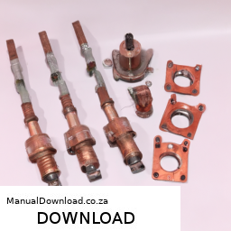
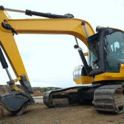
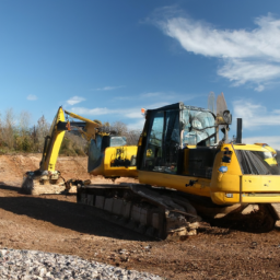
Download Terex TX760B / TX860B / TX970B / TX980B Backhoe Loader Service & Repair Manual –

book shop
Cleaning the throttle body on a Terex TX760B, TX860B, TX970B, or TX980B Backhoe Loader can help improve engine performance and ensure smooth operation. click here for more details on the download manual…..

    Here’s a step-by-step guide to help you do this safely and effectively, even if you have limited mechanical experience.

    ### Tools and Materials Needed:
    – Safety gloves and goggles
    clean rags or paper towels
    – Throttle body cleaner (available at auto parts stores)
    – A small brush (like an old toothbrush)
    – A socket set or wrench (if necessary)
    – Screwdriver set (if necessary)
    – A flashlight (optional)

    ### Step-by-Step Instructions:

    1. **Safety First**:
    – Make sure the backhoe is turned off and parked on a flat surface. Engage the parking brake.
    allow the engine to cool down if it has been running.

    2. **Locate the Throttle Body**:
    open the hood or engine compartment of the backhoe.
    – The throttle body is typically located between the air intake duct and the intake manifold. Look for a round or oval metal component with a large opening.

    3. **Access the Throttle Body**:
    – You may need to remove some components to get to the throttle body, such as the air intake duct. This usually involves loosening clamps or removing screws.
    – Use a screwdriver or socket set to carefully remove any parts that obstruct access.

    4. **Inspect the Throttle Body**:
    – Before cleaning, take a moment to inspect the throttle body for excessive dirt or carbon buildup. This will help you understand how much cleaning is needed.

    5. **Clean the Throttle Body**:
    – Spray the throttle body cleaner into the opening of the throttle body. Be sure to follow the instructions on the cleaner’s label.
    – Use the small brush to gently scrub the inside of the throttle body, focusing on any caked-on dirt or buildup. Be careful not to damage any components.
    – Wipe away the residue with clean rags or paper towels until it’s clean.

    6. **Clean the Throttle Plate**:
    – The throttle plate is a metal flap inside the throttle body that opens and closes to control airflow. clean both sides of the throttle plate carefully.
    – Make sure the throttle plate can move freely without any obstruction.

    7. **Reassemble the Components**:
    – Once everything is clean, reattach any components you removed to access the throttle body. Ensure that all screwsdownload Terex TX760B TX860B TX970B TX980B Backhoe Loader workshop manual and clamps are tightened securely.
    – Double-check that everything is put back in its proper place.

    8. **Test the Backhoe**:
    – Start the engine and let it run for a few minutes. Pay attention to how it idles and responds to throttle input.
    – If everything seems to be working smoothly, you’ve successfully cleaned the throttle body!

    ### Tips:
    – Always consult the owner’s manual for specific instructions related to your model.
    – If you’re unsure about any step, don’t hesitate to ask for help from someone with more mechanical experience.
    – Dispose of any used materials, like rags and paper towels, according to local regulations.

    By following these steps, you can help maintain the performance of your Terex Backhoe Loader while gaining some hands-on experience with basic engine maintenance!
    An armrest is a common yet essential component found in various types of vehicles, including cars, trucks, and SUVs. Typically located between the front seats or at the rear of the vehicle, the armrest serves both functional and aesthetic purposes. Functionally, it provides comfort and support for passengers by allowing them to rest their arms, reducing fatigue on long journeys. It also promotes a more relaxed driving posture, which can enhance the overall driving experience.

    Armrests can vary significantly in design, material, and features. Basic armrests may be simple padded sections, while more advanced versions may include storage compartments, cup holders, or even integrated technology, such as charging ports or controls for audio systems. Some armrests are adjustable, allowing users to change their height or angle for maximum comfort. In premium vehicles, armrests may be upholstered with high-quality materials like leather, providing a luxurious feel.

    In addition to comfort and convenience, armrests also contribute to the vehicle’s interior aesthetics. They can be designed to match the overall theme of the car’s interior, complementing the dashboard and seating materials. Moreover, they play a role in defining the vehicle’s style, whether sporty, elegant, or utilitarian. Overall, the armrest is a small yet significant feature that enhances passenger comfort and elevates the driving experience.

    Download Kobelco MD180LC Service Manual –

    owners manual
    Repairing the transmission cooler on a Kobelco MD180LC excavator involves several steps and requires specific tools. click here for more details on the download manual…..


      SoonParts Water Pump ME037709 ME996936 for Kobelco K907 K907D K907L K909 II K909LC K909LC II MD18… Buy Water Pump ME037709 ME996936 for Kobelco K907 K907D K907L K909 II K909LC K909LC II MD180LC from WWW.

      TD06

    Below is a guide outlining the process, along with detailed descriptions of the tools needed for the repair.

    ### tools and Materials Needed:

    – **Wrenches and Socket Set**:
    – **Description**: A comprehensive set of wrenches and sockets (both metric and standard) is essential for loosening and tightening bolts and fittings on the transmission cooler and surrounding components.

    – **Pliers**:
    – **Description**: Needle-nose and standard pliers are useful for gripping and manipulating small parts, especially hoses and clamps.

    – **Torque Wrench**:
    – **Description**: This tool ensures that bolts are tightened to the manufacturer’s specified torque settings, preventing damage to components or leaks.

    – **Screwdrivers**:
    – **Description**: A set of flat-head and Phillips screwdrivers for removing any screws and securing clamps that may be present.

    – **Hose Cutter or Utility Knife**:
    – **Description**: Used to cut rubber hoses if replacement is necessary. Ensure a clean cut to avoid leaks when installing new hoses.

    – **Coolant and transmission Fluid**:
    – **Description**: Required for refilling the system after the repair. Make sure to use fluids that meet the manufacturer’s specifications.

    – **Replacement Parts**:
    – **Description**: This may include a new transmission cooler, gaskets, seals, and hoses. Ensure that parts are OEM (Original equipment Manufacturer) or of equivalent quality.

    – **Cleaning Supplies**:
    – **Description**: Rags, brushes, and a suitable solvent for cleaning any dirt or debris from the cooler and surrounding area.

    – **Safety Gear**:
    – **Description**: Safety goggles and gloves are essential for protecting yourself from debris and chemicals during the repair process.

    ### Repair Procedure:

    – **Safety First**:
    – Ensure the excavator is parked on a flat surface, the engine is off, and the key is removed. Wear safety goggles and gloves to protect yourself.

    – **Drain the transmission Fluid**:
    – Locate the transmission fluid drain plug and use a wrench to remove it. Allow the fluid to drain completely into a suitable container for disposal.

    – **Remove the transmission Cooler**:
    – Disconnect the hoses attached to the cooler using pliers or a wrench. Be prepared for some residual fluid to spill out.
    – Remove any mounting bolts securing the cooler to the frame or other components. Use the appropriate socket or wrench for this task.
    – Carefully lift the cooler out of its mounting, taking care not to damage any surrounding components.

    – **Inspect the Cooler**:
    – Examine the cooler for signs of damage, such as cracks, corrosion, or clogged passages. If any damage is found, consider replacing the cooler.

    – **Clean the Area**:
    – Use ragsdownload Kobelco MD180LC workshop manual and a solvent to clean the mounting area and any mating surfaces on the cooler.

    – **Install the New or Repaired Cooler**:
    – If replacing, position the new cooler in place and secure it with bolts. Ensure that you use a torque wrench to tighten the bolts to the manufacturer’s specifications.
    – Reconnect the hoses, ensuring they fit snugly and are secured with clamps.

    – **Refill the transmission Fluid**:
    – Locate the filler cap for the transmission fluid and pour in the new fluid as specified in the operator’s manual. Check the fluid level with the dipstick (if applicable) and add more fluid as necessary.

    – **Check for Leaks**:
    – Start the engine and let it run for a few minutes while checking for any leaks around the cooler and connections. If leaks are present, shut down the engine and tighten fittings or replace faulty components.

    – **Final Inspection and Cleanup**:
    – After confirming that there are no leaks, make a final inspection of the area to ensure everything is secure.
    – Dispose of any used fluids and materials according to local regulations, and clean up your work area.

    This guide should help in repairing the transmission cooler on a Kobelco MD180LC excavator. Always refer to the manufacturer’s service manual for specific instructions and torque specifications.
    A brake drum is a crucial component of a drum brake system, commonly found in various vehicles, particularly older models and some lightweight vehicles. It serves as a cylindrical housing that encloses the brake shoes, which are the friction components that press against the drum to slow down or stop the vehicle. When the driver applies the brake pedal, hydraulic force is transmitted through the brake lines to the wheel cylinders, which then push the brake shoes outward against the inner surface of the brake drum.

    The brake drum is typically made of cast iron or a similar durable material to withstand the high temperatures generated during braking. It is designed to dissipate heat effectively, as excessive heat can lead to brake fade, a reduction in braking performance. The inner surface of the drum is machined to create a smooth, even finish, allowing the brake shoes to make optimal contact and produce sufficient friction.

    One of the advantages of brake drums is their ability to provide strong braking force, especially under heavy loads, making them suitable for trucks and trailers. However, they can be heavier and less efficient than modern disc brake systems, which have largely replaced them in many applications. Maintenance of brake drums is essential, as they can wear over time, requiring periodic inspection, resurfacing, or replacement to ensure safe and effective braking performance.

    Download Case CX210C Operators Manual –

    discount
    Suspension repair on a Case CX210C excavator involves several steps and requires a range of tools and equipment. click here for more details on the download manual…..


      Le camion spectaculaire Voici quelle que tour par un camion de marque Cats.

      Piston / Diesel Engine / Excavator #viral #shorts #piston how to install piston rings piston how to assemble pistons how to change piston rings how to install pistons how to assemble …

    Here’s a detailed breakdown of the process and the tools you’ll need:

    – **Safety Gear:**
    – **Safety Glasses:** protects your eyes from debris during the repair.
    – **Gloves:** Provides hand protection.
    – **Steel-Toed Boots:** protects your feet from heavy equipment.
    – **Hard Hat:** Ensures head protection, especially in construction areas.

    – **Basic Hand Tools:**
    – **Wrenches (Metric and Standard):** Used to loosen and tighten bolts and nuts on suspension components.
    – **Sockets and Ratchet Set:** Essential for removing and installing bolts in tight spaces.
    – **Pliers:** Helpful for gripping and bending components.
    – **Screwdrivers (Flat and Phillips):** Useful for removing any covers or panels.
    – **Hammer/Mallet:** Used to persuade stubborn parts apart or into place without damaging them.

    – **Specialized Tools:**
    – **Torque Wrench:** Ensures bolts are tightened to manufacturer specifications, preventing over-tightening or under-tightening.
    – **Ball Joint Separator:** A tool designed to separate the ball joints from the control arms or other suspension components without damage.
    – **Hydraulic Jack:** Used to lift the excavator safely to access suspension components.
    – **Jack Stands:** Essential for supporting the excavator once it’s lifted, ensuring safety during repairs.

    – **Suspension Components:**
    – **Shock Absorbers:** Inspect and replace if leaking or damaged.
    – **Bushings:** Check for wear and replace if cracked or deteriorated as they provide cushioning and reduce vibration.
    – **Control Arms:** Inspect for cracks or bends; replace if damaged.
    – **Springs:** Check for sagging or broken coils and replace if necessary.

    – **Lifting Equipment:**
    – **Forklift or Telehandler:** Helpful for lifting heavy suspension parts if they are too heavy to handle manually.
    – **Chain Hoist:** If working in a confined space, this can assist in lifting heavy components safely.

    – **Fluid Management:**
    – **Fluid Catch Pan:** Used to catch any hydraulic fluid that may leak during repair.
    – **Oil Absorbent Pads:** Helps to clean up any spills and maintain a safe work environment.

    – **Cleaning Supplies:**
    – **Degreaser:** removes grease and grime from suspension components for better visibility and inspection.
    – **Rags and Paper Towels:** For cleaning and wiping down parts during the repair process.

    – **Replacement Parts:**
    – **OEM Parts:** Always advisable to use Original Equipment Manufacturer parts for reliability and compatibility.
    – **Aftermarket Parts:** If opting for aftermarket, ensure they meet quality standards and specifications.

    – **Documentation:**
    – **Service Manual:** Refer to the Case CX210C service manual for specific torque values, part numbers, and repair procedures.
    – **Repair Log:** Maintain records of any repairs performed for future reference and maintenance tracking.

    ### Steps for Suspension Repair:

    – **Preparation:**
    – Park the excavator on a level surface and engage the parking brake.
    – Disconnect the battery to ensure safety while working on electronic components.

    – **Lifting the Excavator:**
    – Use the hydraulic jack to lift the excavatordownload Case CX210C s workshop manual and place jack stands securely under the frame to support it.

    – **Removing Components:**
    – Begin by removing any covers or panels that obstruct access to the suspension parts.
    – Use the appropriate wrenches and sockets to remove bolts securing the shock absorbers, control arms, and other components.

    – **Inspection:**
    – Inspect all removed components carefully for wear and damage. Replace any faulty parts as necessary.

    – **Installation of New Parts:**
    – Install new or refurbished suspension parts, ensuring all bolts are aligned and secured.
    – Use the torque wrench to tighten bolts to the specified torque settings from the service manual.

    – **Reassembly:**
    – Reinstall any covers or panels that were removed.
    – Double-check all connections and ensure nothing is left loose.

    – **Lowering the Excavator:**
    – Carefully remove jack stands and lower the excavator with the hydraulic jack.

    – **Final Checks:**
    – Reconnect the battery and perform a test run to ensure the suspension is functioning correctly and there are no unusual noises or issues.

    – **Cleanup:**
    – Clean the work area, dispose of any waste materials properly, and store tools in their designated places.

    By following these detailed steps and using the appropriate tools, you can carry out a suspension repair on a Case CX210C excavator effectively and safely. Always refer to the manufacturer’s guidelines and safety protocols throughout the process.
    A blow-off valve (BOV) is a crucial component in turbocharged and supercharged engines, primarily designed to manage boost pressure and prevent compressor surge. When the throttle is closed suddenly—such as during rapid deceleration or shifting gears—the sudden drop in intake manifold pressure creates a vacuum that can lead to a dangerous build-up of pressure within the intake system. This is where the blow-off valve comes into play.

    The primary function of a BOV is to release excess boost pressure from the intake system back into the atmosphere or recirculate it into the intake before the turbocharger. When the throttle closes, the BOV opens, allowing pressurized air to escape. This not only prevents compressor surge, which can damage the turbocharger over time, but also helps maintain the efficiency of the turbo system. By venting the excess pressure, the BOV ensures that the turbocharger can continue spinning freely and can react quickly when the throttle is opened again.

    Blow-off valves can be either atmospheric or recirculating. Atmospheric BOVs vent the discharged air to the outside, producing a characteristic “whoosh” sound that is often favored by car enthusiasts. In contrast, recirculating valves redirect the air back into the intake system, helping to maintain pressure and improve overall engine performance.

    Overall, the blow-off valve is an essential component for maintaining the longevity and efficiency of forced induction systems, providing both functional benefits and enhancing the driving experience.

    Download Ford 555 Tractor Backhoe Loader Service Repair Manual –

    purchase
    Replacing a planetary gear set in a Ford 555 Tractor Backhoe Loader is a complex task that requires mechanical skill and understanding of heavy machinery. click here for more details on the download manual…..


      MY Ford Tractor Loader Backhoe will not go forward or reverse For those on the forums and google looking for info on why your Ford Tractor Loader or backhoe With the Power reverser …

      FORD 555 BACKHOE REPAIRS. FORD 555 Backhoe repairs, Nothing major but stuff that needs to be fixed on the new to me Ford dirt swinger. If your new to the …

    This guide will provide a detailed overview of the components involved and the steps necessary to complete the replacement.

    ### Tools and Equipment Needed

    1. **Basic Hand Tools**: Wrenches, sockets, ratchets, and screwdrivers.
    2. **Torque Wrench**: For accurate torque specifications.
    3. **Hydraulic Jack and Jack Stands**: For lifting the machine safely.
    4. **Pry Bars**: To help remove stubborn components.
    5. **Bearing Puller**: Useful for removing bearings.
    6. **Seal Puller**: For removing seals without damaging the housing.
    7. **Clean Rags and Cleaning Solvent**: For cleaning surfaces.
    8. **Grease and Lubricants**: For reassembly.
    9. **Service Manual**: Specific to the Ford 555 for torque specs and detailed diagrams.

    ### Components Involved

    1. **Planetary Gear Set**: The assembly that includes:
    – **Sun Gear**: The central gear that drives the planet gears.
    – **Planet Gears**: The gears that revolve around the sun gear and are mounted on a carrier.
    – **Ring Gear**: The outer gear that meshes with the planet gears.
    – **Carrier**: Holds the planet gears in place and transfers torque.

    2. **Hydraulic Motor**: Provides the necessary power to drive the planetary gear set.

    3. **Housing**: The case that contains the planetary gear set and keeps everything in alignment.

    4. **Seals and Gaskets**: prevent fluid leaks and contain lubrication.

    5. **Bearings**: Support the gears and allow for smooth rotation.

    ### Steps for Replacement

    1. **Preparation**
    – Ensure the tractor is on a flat, stable surface and turn off the engine.
    – Disconnect the battery to prevent accidental starts.
    – Use the hydraulic jack to lift the rear of the tractor and secure it with jack stands.

    2. **Remove the Backhoe Assembly**
    – Disconnect hydraulic lines leading to the backhoe.
    – Remove the pins and brackets securing the backhoe to the tractor frame.
    – Carefully lift and set the backhoe assembly aside.

    3. **Access the Transmission Housing**
    – Remove the access panel or cover on the transmission housing to expose the planetary gear set.

    4. **Drain Fluid**
    – Drain the hydraulic fluid from the transmission to prevent spills and contamination.

    5. **Remove the Planetary Gear Set**
    – Unscrew any bolts securing the planetary gear set housing.
    – Carefully remove the housing to expose the gear set.
    – Take note of the arrangement of gears and carriers for reassembly.
    – Use the bearing puller if necessary to remove the planet gears and carrier.
    – Remove the sun gear and ring gear as needed.

    6. **Inspect Components**
    – Inspect the sun gear, planet gears, and ring gear for wear or damage.
    – Check bearings and seals for signs of wear; replace if necessary.

    7. **Install the New Planetary Gear Set**
    – Begin by placing the new sun gear into position.
    – Install the planet gears onto the carrier, ensuring they mesh properly with the sun gear.
    – Attach the ring gear to the housing, ensuring it aligns correctly with the planet gears.
    – Secure all components in place with the appropriate fasteners, torquing them to specification.

    8. **Reassemble the Transmission Housing**
    – Replace any sealsdownload Ford 555 Tractor Backhoe Loader workshop manual and gaskets before reattaching the housing cover.
    – Ensure all bolts are tightened to the required torque specifications.

    9. **Reconnect the Backhoe Assembly**
    – Reattach the backhoe to the tractor frame, ensuring all pins and brackets are secure.
    – Reconnect hydraulic lines, checking for proper connections.

    10. **Refill Fluid**
    – Refill the hydraulic system with the appropriate hydraulic fluid as per the service manual.

    11. **Test the System**
    – Reconnect the battery and start the tractor.
    – Test the backhoe and planetary gear operation to ensure everything is functioning correctly.

    ### Final Checks

    – **Leak Inspection**: After running the tractor, inspect for any leaks around the seals and gaskets.
    – **Function Test**: Operate the backhoe to ensure smooth operation without unusual noises.

    ### Conclusion

    Replacing a planetary gear set in a Ford 555 Tractor Backhoe Loader is a detailed process that requires careful attention to detail and proper reassembly. Always refer to the manufacturer’s service manual for specific torque specifications and additional instructions for your particular model. If you’re not comfortable performing this task, consider consulting a professional mechanic.
    A brake line is a crucial component of a vehicle’s braking system, responsible for transferring hydraulic pressure from the brake pedal to the brake calipers or brake drums at each wheel. Brake lines are typically made from high-strength materials such as steel or reinforced rubber, designed to withstand the high pressures generated when the brakes are applied. The primary function of the brake line is to convey the brake fluid, which is essential for the hydraulic braking mechanism to function effectively.

    When a driver presses the brake pedal, the force is transmitted through the master cylinder, which generates hydraulic pressure in the brake fluid. This pressure travels through the brake lines to the brake calipers (in disc brake systems) or brake cylinders (in drum brake systems), causing them to engage and apply friction to the brake rotors or drums. This friction is what ultimately slows down or stops the vehicle.

    Brake lines are designed to handle extreme conditions, including high temperatures and exposure to road debris and chemicals. Over time, however, they can develop issues such as leaks, corrosion, or wear, which can compromise braking performance and pose significant safety risks. Regular inspection and maintenance of brake lines are essential to ensure they remain in good condition, as any failure in this component can lead to brake failure, endangering the vehicle occupants and others on the road.

    Download Volvo EC210 ExcavatorService & Repair Manual –

    repairs
    Replacing a wheel bearing on a Volvo EC210 Excavator involves several steps that should be followed in reverse order after completing the replacement. click here for more details on the download manual…..


      VOLVO EC480D Differential Valve VOLVO Excavator EC480D Differential Valve!

      #full out final drive #leaked #volvo excavator ec210 blc

    Here’s a reverse order guide to help you understand the process:

    ### 7. Reassemble Everything
    – **Reinstall the Wheel:** Align the wheel with the hub and secure it using the lug nuts. Tighten them to the manufacturer’s specified torque.
    – **Reattach the Brake Caliper:** If applicable, reattach the brake caliper to the wheel assembly, ensuring all bolts are tightened correctly.
    – **Reconnect Any Covers or Shields:** If you removed any dust covers or shields, reinstall them to protect the bearing.

    ### 6. Prepare for Assembly
    – **Clean the Area:** Ensure that the area around the wheel hub is clean and free from debris or contaminants.
    – **Apply Grease:** If the new bearing requires it, apply a suitable grease to the bearing before installation.

    ### 5. Install the New Wheel Bearing
    – **Position the New Bearing:** Carefully place the new bearing into the wheel hub.
    – **Press In the Bearing:** Use a bearing press or appropriate tool to press the new bearing into place, ensuring it is seated evenly.

    ### 4. Remove the Old Wheel Bearing
    – **Extract the Old Bearing:** If necessary, use a bearing puller to remove the old bearing from the hub.
    – **Inspect for Damage:** Check the hub for any signs of damage or wear that may need addressing before installing the new bearing.

    ### 3. Prepare the Hub
    – **Remove the Wheel:** Use a wrench to loosen and remove the lug nuts, and then take off the wheel.
    – **Access the Bearing:** If there are any additional components blocking access to the bearing, remove them as necessary (e.g., brake components, dust covers).

    ### 2. Gather Tools and Parts
    – **Gather Required Tools:** Ensure you have the necessary tools such as a lug wrench, bearing puller, bearing press, torque wrench, and any other specific tools needed for the Volvo EC210.
    – **Acquire New Parts:** Obtain the correct replacement wheel bearing for your Volvo EC210 Excavator.

    ### 1. Safety Precautions
    – **Park on Level Ground:** Ensure the excavator is parked on stable, level ground.
    – **Engage the Parking Brake:** Always engage the parking brake to prevent movement.
    – **Wear Safety Gear:** Put on appropriate safety gear, including glovesdownload Volvo EC210 Excavator workshop manual and eye protection.

    ### Conclusion
    Following these steps in reverse order gives you a comprehensive overview of the wheel bearing replacement process for a Volvo EC210 Excavator. Always refer to the manufacturer’s service manual for specific torque specifications and detailed instructions tailored to your model.
    The AC compressor is a crucial component of an automobile’s air conditioning system, responsible for circulating refrigerant and maintaining the cooling process within the vehicle. It functions as a pump that compresses low-pressure refrigerant gas into a high-pressure gas, which is then sent to the condenser. The compressor is typically driven by a belt connected to the engine, allowing it to convert mechanical energy into the energy needed for refrigeration.

    When the air conditioning system is activated, the compressor engages, and the refrigerant, which is usually a chlorofluorocarbon or hydrofluorocarbon, absorbs heat from the cabin air and transforms into a gas. The compressor’s role is to increase the pressure and temperature of this gas before it is sent to the condenser located at the front of the vehicle. In the condenser, the refrigerant releases its heat to the outside air, transforming back into a liquid state. This liquid is then routed to the expansion valve or orifice tube, where it experiences a drop in pressure, allowing it to cool down further before returning to the evaporator inside the cabin.

    Overall, the AC compressor is vital for ensuring that the air conditioning system operates efficiently, providing a comfortable environment for passengers by regulating cabin temperature and humidity levels. A malfunctioning compressor can lead to reduced cooling performance or complete failure of the air conditioning system, making its maintenance and timely repair essential for vehicle comfort.

    Download Volvo EC140C L (EC140CL) Excavator Service Repair Manual-

    workshop manual
    Performing engine diagnostics on a Volvo EC140C L EC140CL Excavator involves a systematic approach to identify and troubleshoot issues. click here for more details on the download manual…..


      Volvo EC140 Excavator: COOLING FAN HUB, RADIATOR, OIL COOLER INSTALLATION. Part #3. Volvo EC140 Excavator: COOLING FAN HUB, RADIATOR, OIL COOLER INSTALLATION. Part #3. Simple Step by step installation …

    Here’s a reverse order of the steps you might follow, assuming you have access to the operator’s manual and the necessary tools:

    ### 7. Document Findings
    – Record all diagnostics results, error codes, and observations.
    – Take note of any patterns or recurring issues for future reference.

    ### 6. Analyze Data
    – Review the diagnostic results and error codes retrieved from the machine’s onboard computer.
    – Cross-reference the codes with the manual to identify specific faults or issues.

    ### 5. Conduct Tests
    – Perform any additional tests recommended in the manual, such as checking fuel pressure, air intake, or exhaust emissions.
    – Use a multimeter to check electrical connections, sensors, and other components as needed.

    ### 4. Retrieve diagnostic Codes
    – Connect a diagnostic tool or computer to the excavator’s diagnostic port.
    – Power on the machine and access the engine control unit (ECU) to retrieve any stored error codes.

    ### 3. Inspect Components
    – Visually inspect the engine and related components for signs of wear, damage, or leaks.
    – Check the condition of the air filters, fuel filters, belts, and hoses.

    ### 2. Prepare for Diagnostics
    – Ensure that the excavator is on a flat, stable surface and the engine is cool.
    – Gather necessary tools, such as a diagnostic scanner, multimeter, and basic hand tools.

    ### 1. Consult the Manual
    – Refer to the Volvo EC140C L EC140CL Excavator manual for specific diagnostic procedures and troubleshooting flowcharts.
    – Familiarize yourself with the engine specifications and recommended diagnostic practices.

    By following these steps in reverse order, you can effectively perform engine diagnostics on the Volvo EC140C L EC140CL Excavator. always prioritize safetydownload Volvo EC140C L EC140CL Excavator Manual workshop manual and consult the manual for detailed Instructions and specifications.
    The rear axle is a critical component of a vehicle’s drivetrain, primarily responsible for transferring power from the engine to the rear wheels, enabling movement and handling. It plays a vital role in the overall performance and stability of the vehicle, particularly in rear-wheel-drive setups, where the engine’s power is directed to the rear wheels. The rear axle consists of several key parts, including the axle housing, axle shafts, differential, and sometimes the brake assembly.

    The axle housing encloses the differential and axle shafts, providing structural integrity and housing lubricant to minimize friction. The differential is crucial as it allows the rear wheels to rotate at different speeds while cornering, which is essential for maintaining traction and stability. Without a functioning differential, vehicles would struggle to navigate turns effectively, leading to excessive tire wear and potential loss of control.

    The axle shafts are connected to the wheels and transmit power from the differential to the wheels. Additionally, the rear axle may incorporate features such as limited-slip differentials for enhanced traction in slippery conditions, or it may be part of a more complex independent suspension system, which improves ride quality and handling.

    Overall, the rear axle is integral not just to propulsion but also to the overall dynamics of a vehicle, influencing factors like handling, ride comfort, and safety. Regular maintenance of the rear axle, including checking fluid levels and inspecting for wear, is essential for reliable vehicle operation.

    Download Hyundai Crawler Excavator R360LC-3 Service Repair Manual –

    sale
    Replacing the timing chain on a Hyundai Crawler Excavator R360LC-3 is a complex procedure that requires careful planning and execution. click here for more details on the download manual…..


      HYUNDAI R360LC-7 2006 MODELL

    Below is a detailed step-by-step guide, including descriptions of the necessary tools and equipment needed for the job.

    ### Tools and Equipment Needed:

    – **Socket Set**: A complete metric socket set (including deep sockets) to fit various bolt sizes on the engine.
    – **Wrenches**: A set of combination wrenches in metric sizes for access to tighter spaces.
    – **Torque Wrench**: A precision tool to ensure that bolts are tightened to the manufacturer’s specified torque settings.
    – **Pliers**: For removing clips and other small fasteners.
    – **Screwdrivers**: Both flathead and Phillips for various components and covers.
    – **Timing Chain Kit**: This usually includes the timing chain, sprockets, and sometimes new tensioners or guides.
    – **Engine Oil**: To lubricate the new timing chain upon installation.
    – **Gasket Sealant**: For resealing any covers that are removed during the process.
    – **Oil Catch Pan**: To collect any oil that may spill during the process.
    – **Shop Manual**: A service manual specific to the Hyundai R360LC-3 for reference to specifications and diagrams.
    – **Crankshaft Pulley Holder Tool**: To prevent the crankshaft from turning while loosening the crankshaft bolt.
    – **Timing Light (optional)**: For verifying timing after the installation is complete.
    – **Safety Gear**: Gloves, goggles, and a hard Hat to ensure personal safety.

    ### Step-by-Step Procedure:

    – **Preparation**:
    – Ensure the excavator is parked on a level surface and that the engine is cool.
    – Disconnect the battery to prevent any electrical issues during the process.

    – **Drain Engine Oil**:
    – Place an oil catch pan underneath the engine oil pan and remove the drain plug to let the oil drain completely.

    – **Remove Engine Covers**:
    – Use the socket set and wrench to remove any covers obstructing access to the timing chain. This includes the valve cover and front timing cover.
    – Be careful Not to damage any gaskets; you may need to replace them later.

    – **Align Timing Marks**:
    – Rotate the crankshaft using a socket wrench on the crankshaft pulley bolt until the timing marks on the crankshaft and camshaft sprockets are aligned. This is crucial to ensure that the engine is at top dead center (TDC) before removing the timing chain.

    – **Remove Old Timing Chain**:
    – Use the appropriate tools to remove the tensioner and guides. This may involve removing additional bolts or components depending on the engine design.
    – Once the tensioner and guides are removed, carefully take off the old timing chain and sprockets.

    – **Inspect Components**:
    – Check the condition of the camshaft and crankshaft sprockets for wear. If they show significant wear, replace them as part of the timing chain kit.
    – Inspect the tensioner and guides for damage or wear. Replace them if necessary.

    – **Install New Timing Chain**:
    – Position the new timing chain around the crankshaft and camshaft sprockets, ensuring that the timing marks remain aligned.
    – Install the new tensioner and guides, following the manufacturer’s specifications for torque settings.

    – **Reassemble Engine Covers**:
    – Replace any gaskets that were removed,download Hyundai Crawler Excavator R360LC 3 workshop manual and apply gasket sealant if required.
    – Reinstall the front timing cover and the valve cover, tightening bolts to the recommended torque settings from the shop manual.

    – **Refill Engine Oil**:
    – Replace the drain plug after the oil has drained completely and refill the engine with new engine oil.

    – **Reconnect Battery**:
    – Reconnect the battery terminals.

    – **Start the Engine**:
    – Start the engine and allow it to idle for a few minutes. Check for any unusual noises or leaks.
    – If equipped, use a timing light to verify that the timing is set correctly.

    – **Final Checks**:
    – Once everything is confirmed to be operating normally, perform a final inspection of all bolts and ensure that all tools are removed from the engine bay.

    ### Safety Considerations:

    – Always wear personal protective equipment (PPE) such as gloves and safety glasses.
    – Ensure that the machine is secured and cannot roll or move during the repair.
    – Follow all manufacturer guidelines and safety protocols when performing maintenance.

    By following these steps carefully and using the appropriate tools, you can successfully replace the timing chain on a Hyundai Crawler Excavator R360LC-3. Always refer to the specific service manual for your machine for any additional details or specifications.
    The oil drain plug is a critical component found in the oil pan of an internal combustion engine. Its primary function is to provide a means for draining engine oil during routine maintenance, such as oil changes. Typically made of metal, the oil drain plug is designed to withstand high temperatures and pressures associated with engine operation. It features a threaded design that allows it to be securely fastened to the oil pan, preventing oil leaks and ensuring the engine remains lubricated.

    When performing an oil change, the mechanic or vehicle owner will remove the oil drain plug to allow the old, used oil to flow out completely. This process Not only helps in removing contaminants and debris that accumulate in the oil over time but also allows for the replacement of old oil with fresh oil, which is essential for optimal engine performance. The plug often comes with a washer or gasket to create a tight seal and minimize the risk of leakage.

    In addition to its functional role, the oil drain plug can also serve as an inspection point. Some designs incorporate a magnet to attract metal particles, allowing for early detection of wear or potential issues within the engine. regular inspection and maintenance of the oil drain plug are essential, as a damaged or improperly sealed plug can lead to significant oil leaks, resulting in engine damage and reduced vehicle performance. Overall, the oil drain plug is a small yet vital part of an engine’s lubrication system, playing a key role in maintaining the engine’s health and efficiency.

    Download KOMATSU PC27MR-3 PC30MR-3 PC35MR-3 Excavator Service Manual –

    get
    Replacing the strut mount on a KOMATSU PC27MR-3, PC30MR-3, or PC35MR-3 excavator involves several steps, and while it’s generally recommended to follow the instructions in a forward manner, I can outline the process in reverse order for you. click here for more details on the download manual…..


      Sold! 2012 Komatsu PC27MR-3 Hydraulic Mini Excavator Aux Hyd bidadoo.com This unit sold at no-reserve auction on 3/29/2018. bidadoo is the largest and most trusted online auction service. We feature …

      Replacement Radiator Thank Mini Excavator Komatsu PC50

    ### Reverse Order Steps for Strut Mount Replacement:

    1. **Reassemble the Components:**
    – Reattach any covers, panels, or components that were removed to access the strut mount.
    – Ensure all bolts and fasteners are tightened to the manufacturer’s specifications.

    2. **Install the New Strut Mount:**
    – Position the new strut mount in place, ensuring it aligns correctly with the mounting points.
    – Secure the strut mount with the bolts, tightening them in a crisscross pattern to ensure even pressure.

    3. **Reconnect the Strut:**
    – Align the strut with the new mount and carefully reattach it, ensuring it is secure.
    – Tighten the strut bolts to the specified torque settings.

    4. **Lower the Excavator:**
    – Once everything is reconnected, lower the excavator If it was raised on jacks or stands.

    5. **Remove the Old Strut Mount:**
    unscrew and remove the old strut mount from its position, ensuring no debris falls into the assembly.

    6. **Disconnect the Strut:**
    – Carefully detach the strut from the current mount, taking care Not to damage any surrounding components.

    7. **Prepare for Replacement:**
    – Raise the excavator using appropriate jacks or stands to gain access to the strut and mount.
    – Ensure the work area is safe and clear of any hazards.

    ### Additional Tips:
    – Always consult the specific service manual for the KOMATSU excavator model you are working on for detailed instructions, torque specifications, and safety guidelines.
    – Use proper safety equipment and procedures when working on heavy machinery.
    – It may be helpful to have a second person assist with holding components in place during the installation.

    By following these reverse steps, you can better visualizedownload KOMATSU PC27MR 3 PC30MR 3 PC35MR 3 Excavator workshop manual and understand the entire process of replacing the strut mount on the KOMATSU PC27MR-3, PC30MR-3, or PC35MR-3 excavator.
    A sway bar link, also known as a stabilizer link or anti-roll bar link, is an essential component of a vehicle’s suspension system that plays a crucial role in enhancing stability and handling. It connects the sway bar (or anti-roll bar) to the vehicle’s suspension components, typically the control arms or struts. The sway bar itself is designed to reduce body Roll during cornering, which helps maintain tire contact with the road and improves overall vehicle control.

    The sway bar link consists of a metal rod with bushings or ball joints at each end, allowing for flexibility and movement as the suspension travels over bumps and irregularities in the road. When a vehicle turns, the sway bar transfers the weight of the vehicle towards the outside wheels, minimizing tilt and ensuring a more balanced ride. This action helps to improve traction and responsiveness, making the vehicle feel more stable and secure during maneuvers.

    Over time, sway bar links can wear out due to exposure to road conditions, corrosion, and the repetitive motion of the suspension system. Symptoms of a failing sway bar link may include clunking noises during turns, a loose or unstable feeling while driving, or excessive body roll. Regular inspection and timely replacement of worn sway bar links are essential for maintaining optimal vehicle performance and safety.

    Download Model 520 530 533 Skid Steer Loader Repair Manual –

    service
    Replacing the struts on a Bobcat 520, 530, or 533 Skid Steer Loader requires careful attention to detail and safety precautions. click here for more details on the download manual…..

        Here’s a detailed guide on how to perform this task.

        ### Tools and materials Needed:
        1. **Tools:**
        – Wrenches (sized for your specific bolts, typically 3/8″, 1/2″, and 9/16″)
        – Socket set
        – Torque wrench
        – Floor jack or hydraulic jack
        – Jack stands
        – Pry bar
        – Screwdrivers (flathead and Phillips)
        – Hammer
        – Safety goggles
        – Gloves

        2. **Materials:**
        – Replacement struts (specific to model 520, 530, or 533)
        – New bolts/nuts (if necessary)
        – Lubricant or anti-seize compound
        – Cleaning rags

        ### Step-by-Step Procedure:

        #### **1. Safety First**
        – Park the skid steer on a flat, stable surface.
        – Engage the parking brake and turn off the engine.
        – Disconnect the battery by removing the negative terminal to prevent any accidental starts.

        #### **2. Lift the Skid Steer**
        – Use a floor jack to lift the front of the skid steer.
        – Place jack stands under the frame to secure it in place. Ensure the skid steer is stable.

        #### **3. Remove the Old Struts**
        – **Locate the Struts:** The struts are typically located at each corner of the skid steer’s frame where the loader arms are connected.

        – **Remove Bolts:** Using the appropriate socket and wrench, remove the bolts securing the strut to the frame and to the loader arm. there may be a bolt at the top and bottom of each strut.

        – **Detach the Strut:** After the bolts are removed, you may need to gently tap the strut with a hammer to loosen it. If it’s stuck, a pry bar can help leverage it out. Be cautious not to damage surrounding components.

        #### **4. Prepare for New Strut Installation**
        – **Clean the Area:** Wipe down the mounting points on the skid steer to remove any dirt or debris. This ensures a good fit for the new struts.
        – **Inspect Other Components:** While you have the strut area accessible, inspect related components like bushings and bolts for wear. Replace them If necessary.

        #### **5. install the New Struts**
        – **Position the New Strut:** Align the new strut in its mounting position. It should fit snugly into place.

        – **Insert Bolts:** Start threading the bolts by hand to avoid cross-threading. Once they are in place, use a wrench to tighten them, but do not fully tighten yet.

        – **Torque Specifications:** Refer to the service manual for the specific torque settings for the strut bolts. Use a torque wrench to tighten the bolts to the recommended specifications.

        #### **6. Reassemble and Lower the Skid Steer**
        – **Check Alignment:** Ensure the strut is properly aligneddownload 520 530 533 Skid Steer Loader workshop manual and seated in its mounts.

        – **Lower the Skid Steer:** Carefully remove the jack stands and lower the skid steer back to the ground using the floor jack.

        #### **7. Reconnect Battery and Test**
        – Reconnect the negative battery terminal.
        – Start the skid steer and test the functionality of the loader arms and struts. Listen for any unusual noises and check for proper operation.

        #### **8. Final Inspection**
        – After a short test run, inspect the strut installation and ensure everything is secure. Look for any signs of leaks or misalignment.

        ### Conclusion:
        Replacing the struts on a Bobcat 520, 530, or 533 Skid Steer Loader can be completed with careful attention to detail and safety. Always refer to the specific service manual for your model for any particular instructions or torque specifications. If you’re unsure about any part of the process, it’s wise to consult with a professional mechanic or technician.
        The exhaust manifold is a critical component of an internal combustion engine, designed to collect and channel exhaust gases from multiple cylinders to a single outlet, typically leading to the exhaust system. Its primary function is to efficiently direct the spent gases generated during the combustion process away from the engine, thereby reducing back pressure and optimizing engine performance.

        Manufactured from materials such as cast iron or stainless steel, the exhaust manifold is engineered to withstand high temperatures and corrosive exhaust gases. The design typically features separate channels for each cylinder’s exhaust output, merging into a common outlet. This configuration helps to minimize turbulence and maximize the flow of exhaust gases, which is essential for maintaining engine efficiency and power.

        Additionally, the exhaust manifold plays a role in controlling emissions. It is often equipped with features that allow for the integration of components such as catalytic converters, which further reduce harmful pollutants before they exit the vehicle.

        Over time, exhaust manifolds can be subjected to thermal cycling, leading to potential cracks or leaks, which can compromise engine performance and increase emissions. Therefore, regular inspection and maintenance are crucial to ensure the manifold remains in good condition, contributing to the overall efficiency and longevity of the vehicle’s engine.

        Download Case CX130 CX160 CX180 Excavator Complete Workshop Service Repair Manual –

        diy
        Certainly! click here for more details on the download manual…..


          IN GOD – How to change Fuel Filters & reset computer for CX160D Case Track hoe CX160D Case Tr… This Video will show how the reset the computer too after you have changed the Fuel Filters the CX160D Case Track hoe.

          2004 CASE CX130 2004 CASE CX130 for sale on equipmenttrader.com: …

        Here’s a step-by-step guide to checking the engine light on a Case CX130, CX160, or CX180 Excavator, presented in reverse order:

        ### 6. **Consult the Manual**
        – Refer to the operator’s manual specific to your Case excavator model for troubleshooting steps and error code definitions.

        ### 5. **Clear Codes (if necessary)**
        – If you have resolved the issue, you may want to clear any trouble codes using a diagnostic tool to reset the check engine light.

        ### 4. **Read Diagnostic Codes**
        – Use an appropriate diagnostic tool to connect to the excavator’s onboard diagnostic system.
        – Retrieve any stored diagnostic trouble codes (DTCs) that can provide insight into the issue causing the check engine light.

        ### 3. **Inspect for Obvious Issues**
        – Perform a visual inspection of the engine compartment and surrounding components for any obvious signs of trouble, such as loose or damaged wires, leaks, or unusual sounds.

        ### 2. **Turn on the Ignition**
        – Without starting the engine, turn the ignition key to the “On” position. Observe whether the check engine light illuminates and stays on momentarily as part of the self-test.

        ### 1. **Start the Engine**
        – Start the excavator’s engine and observe the check engine light. If it remains lit after the initial self-test, further investigation is required.

        By following these steps in reverse order, you can efficiently identify and address the issue related to the check engine light on your Case excavator.
        The Gear selector, also known as the Gear shift or transmission lever, is a crucial component in both manual and automatic vehicles that allows the driver to select the appropriate Gear for the desired speeddownload Case CX130 CX160 CX180 Excavator workshop manual and power. Its primary function is to engage and disengage the transmission gears, enabling the car to operate efficiently across various driving conditions. In manual vehicles, the Gear selector is typically a stick or lever that the driver moves through a series of defined positions—often labeled with numbers indicating the gears (1 through 5 or 6) and a reverse gear. This type of selector requires the driver to coordinate the use of the clutch pedal, allowing for smooth transitions between gears while managing engine speed and power output.

        In automatic vehicles, the Gear selector functions differently. It often incorporates a more complex mechanism that automatically adjusts the gears based on the vehicle’s speed and acceleration needs. The driver can select different modes, such as “Park,” “Reverse,” “Neutral,” and “Drive,” each serving distinct purposes. Advanced automatic systems may also include additional settings such as “Sport” for performance driving or “Eco” for fuel efficiency. With the advent of modern technology, some vehicles now feature electronic Gear selectors, which rely on buttons or touchscreens instead of traditional levers, providing a sleeker design and potentially quicker Gear changes. Overall, the Gear selector plays a fundamental role in vehicle operation, influencing performance, safety, and driver convenience.