
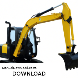
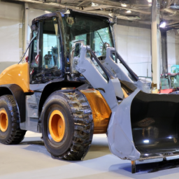
Replacing the strut mounts on a Case 580N, 580SN, 580SN WT, or 590SN involves several steps and requires specific tools and safety precautions. click here for more details on the download manual…..
- Case 580ST Backhoe Loader DPF Problem [Solved] In this video we talk about solving a 2016 Case 580ST Backhoe Loader DPF with problem .The DPF of this equipment is known to …
Below is a detailed guide, including the description of each tool needed for the task:
### Tools and Equipment Needed
– **Jack and Jack Stands**:
– Used to lift the machine safely and securely, allowing access to the strut mounts. Ensure the jack is rated for the weight of the machine.
– **Wrenches (Metric and Standard)**:
– Required for loosening and tightening bolts. A set that includes both open-end and box-end wrenches will be beneficial.
– **Socket Set**:
– A ratchet and various socket sizes are necessary for removing the bolts securing the strut mounts. A deep socket set may be particularly useful for accessing bolts in tight spaces.
– **Pry Bar**:
– Useful for gently levering components apart if they are stuck or not coming free easily. Be cautious to avoid damaging other components.
– **Torque Wrench**:
– Essential for tightening bolts to the manufacturer’s specified torque settings, ensuring safety and proper function.
– **Impact Wrench (optional)**:
– Can make removing stubborn bolts easier and faster, especially if they are rusted or corroded.
– **Rubber Mallet**:
– Helps in tapping components into place without damaging them.
– **Safety Gear**:
– Includes gloves, safety glasses, and steel-toed boots to protect against injuries during the replacement process.
### replacement Process
– **Preparation**:
– Park the machine on a flat, stable surface. Ensure the parking brake is engaged, and the engine is turned off. Remove the key to prevent accidental startup.
– **Lifting the Machine**:
– Use the jack to lift the machine. Place jack stands underneath for additional safety. Ensure the vehicle is secure before working underneath.
– **Accessing the Strut Mounts**:
– Depending on the specific configuration, you may need to remove certain panels or components to access the strut mounts. Take note of how they are installed for reassembly.
– **Removing Old Strut Mounts**:
– Use the socket set or wrenches to remove the bolts securing the strut mounts. If the bolts are stubborn, apply penetrating oil and allow it to sit for a few minutes before attempting removal. Use a pry bar if necessary to help free the mounts.
– **Inspecting Strut Mounts and Surrounding Components**:
– Check the old strut mounts for signs of wear or damage. Inspect surrounding components for any potential issues that may need attention, such as bushings or mounts.
– **Installing New Strut Mounts**:
– Position the new strut mounts in place. Start the bolts by hand to ensure they are not cross-threaded, then tighten them with the socket set or wrenches.
– **Torque Specifications**:
– Refer to the machine’s service manual for the proper torque specifications for the strut mount bolts. Use the torque wrench to tighten the bolts to the specified settings.
– **Reassembling Components**:
– If you removed any panels or other components to access the strut mounts, reinstall them in reverse order. Ensure all bolts and fasteners are tightened appropriately.
– **Lowering the Machine**:
– Carefully remove the jack stands and lower the machine using the jack. Ensure the area is clear before lowering.
– **Testing**:
– Once the machine is back on the ground, perform a test run to ensure everything is functioning correctly. Listen for any unusual noises that may indicate improper installation.
– **Final Inspection**:
– After testing, do a final inspection of the strut mounts and surrounding areas to ensure everything is secure and there are no leaks or issues.
### Safety Tips
– Always use appropriate safety Gear to protect yourself.
– Ensure the machine is stable before working under it.
– Follow all manufacturer guidelines and consult the service manual for any specific instructions related to your machine model.
This guide outlines the steps and tools necessary for strut mount replacement on Case 580N, 580SN, 580SN WT, and 590SN models. Always refer to the official service manual for detailed specifications and torque settings.
The intake air temperature (IAT) sensor is a crucial component of an internal combustion engine’s air intake system. Its primary function is to monitor the temperature of the air entering the engine. This data is vital for the engine control unit (ECU) to optimize fuel injection and ignition timing, ensuring efficient combustion and overall engine performance.
Typically located in the intake manifold or within the air intake duct, the IAT sensor usually employs a thermistor, which is a type of resistor whose resistance changes with temperature. As the intake air temperature fluctuates, the sensor sends corresponding voltage signals to the ECU. The ECU uses this information to adjust the air-fuel mixture; warmer air is less dense and contains less oxygen, requiring a different fuel mixture compared to cooler air.
Accurate readings from the IAT sensor are essential for achieving optimal engine performance, fuel efficiency, and emissions control. A malfunctioning sensor can lead to incorrect air-fuel mixture calculations, resulting in symptoms like poor acceleration, reduced fuel economy, engine misfires, or even stalling. In modern vehicles, the IAT sensor often works in conjunction with other sensors, such as the mass air flow (MAF) sensor and the coolant temperature sensor, to provide a comprehensive view of the engine’s operating conditions. Regular checks and maintenance of the IAT sensor can help ensure the vehicle runs smoothly and efficiently.
 and safety equipment.
 and additional guidance.
 and mounting points for any defects that need addressing.
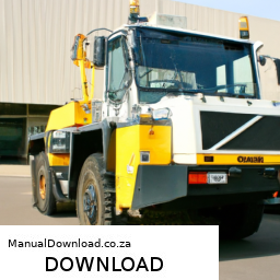
 and amount.
 and then lower the wheel loader back to the ground before fully tightening the lug nuts in a crisscross pattern.
 and torque specifications for your particular model.
 and engine. Apply
 and consult the manual or a professional if needed.
 and safety guidelines.