
Repairing the torque converter clutch on a Liebherr L556 1288 wheel loader can be a complex task, especially for someone with little mechanical experience. click here for more details on the download manual…..
- How To Replace Rear Hub Bearing Assemblies – Dodge Neon (Andy’s Garage: Episode – 403) In this video, Andy Phillips shows step by step how to replace the rear hub bearing assembly on a Dodge Neon. Replacing a hub …
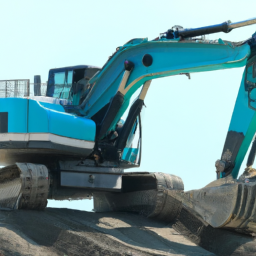
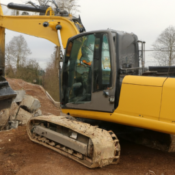
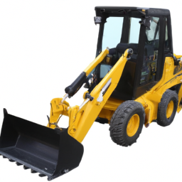
- LIEBHERR L556 shovel – wheel loader www.tijs.nl €72500 Brand: LIEBHERR Type: L556 Year of construction: 2016 Hours: 8177 SN number: 1288-41621 – additional; …
However, I’ll break it down into simpler terms so you can understand the general process. Please remember that it’s always best to consult the operator’s manual or a professional mechanic for specific guidance.
### What is a Torque Converter and a Clutch?
1. **Torque Converter**: This is a component in your wheel loader’s transmission that helps to transfer power from the engine to the wheels. It allows the vehicle to move without stalling and provides a smoother driving experience.
2. **Clutch**: The torque converter has a clutch that locks the converter to the engine at higher speeds to improve efficiency. Sometimes, this clutch can fail, causing issues like slipping or overheating.
### Basic Steps for Repairing the Torque Converter Clutch
#### 1. **Safety First**
– Ensure that the wheel loader is turned off, parked on a flat surface, and the key is removed.
– Wear safety goggles and gloves to protect yourself.
#### 2. **Gather Tools and Materials**
– You will need basic tools such as wrenches, sockets, screwdrivers, and possibly a jack and jack stands.
– Replacement parts like the torque converter clutch or seals may also be needed.
#### 3. **Accessing the Torque Converter**
– **Remove the access Panel**: Depending on the design of the Liebherr L556, you may need to remove the cover or access panel to get to the torque converter. This usually involves unscrewing a few bolts.
– **Locate the Torque Converter**: It will be near the engine and connected to the transmission.
#### 4. **Disconnecting Components**
– **Fluid Lines**: Carefully disconnect any hydraulic lines connected to the torque converter. Be prepared for some hydraulic fluid to spill, so have a container ready to catch it.
– **Electrical Connections**: If there are any electrical connectors, disconnect them as well.
#### 5. **Removing the Torque Converter**
– **Unbolt the Torque Converter**: There will be bolts holding the torque converter in place. Use the appropriate socket to remove them.
– **Carefully Pull It Out**: Once unbolted, gently pull the torque converter away from the engine. Be cautious, as it can be heavy.
#### 6. **Inspecting and Repairing**
– **Check for Damage**: Look for any signs of wear or damage on the clutch and torque converter. If the clutch is worn out, it will need to be replaced.
– **Replace the Clutch**: If necessary, remove the old clutch and install a new one according to the instructions provided with the replacement part.
#### 7. **Reinstalling the Torque Converter**
– **Align and Insert**: Carefully align the torque converter back into place and push it towards the engine.
– **Bolt It Back**: Reattach the bolts to secure the torque converter.
#### 8. **Reconnecting Components**
– **Reconnect Hydraulic Lines**: Reattach any fluid lines and tighten them securely.
– **Reconnect Electrical Connections**: If you disconnected any electrical components, reconnect them.
#### 9. **Final Steps**
– **Replace the access Panel**: Once everything is back in place, replace the access panel and secure it with screws.
– **Refill Fluids**: If any hydraulic fluid was lost, refill it to the appropriate level.
– **Test the Loader**: start the wheel loader and test the operation of the torque converter clutch to ensure it’s working properly.
### Conclusion
Repairing the torque converter clutch on a Liebherr L556 wheel loader can be challenging without mechanical experience. Always prioritize safety and consider seeking help from a professional mechanic if you’re uncertain about any step. Additionally, referring to the manufacturer’s service manual will provide specific details tailored to your machine.
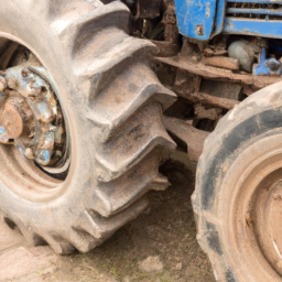
A tire is a crucial component of a vehicle, serving as the interface between the car and the road. Constructed from layers of rubber, fabric, and steel, tires are designed to provide traction, stability, and support for the weight of the vehicle. They come in various types and sizes, tailored to different driving conditions and vehicle requirements, including passenger cars, trucks, and specialized vehicles.
The primary function of a tire is to provide grip on the road surface, allowing for safe acceleration, braking, and cornering. The tread pattern on the tire plays a significant role in this aspect, as it is engineered to channel water away, reducing the risk of hydroplaning and enhancing traction in wet conditions. Tires are also designed to absorb shocks from bumps and irregularities in the road, contributing to a smoother ride for passengers.
Tires are categorized into various types such as all-season, winter, and performance tires, each optimized for specific driving conditions. Regular maintenance, including checking air pressure and tread depth, is essential for tire longevity and vehicle safety. Additionally, tire technology has evolved significantly, with advancements in materials and design improving fuel efficiency, reducing road noise, and enhancing performance. Overall, tires are integral to vehicle safety and performance, influencing everything from handling to fuel economy.

 and clamps are tightened securely.
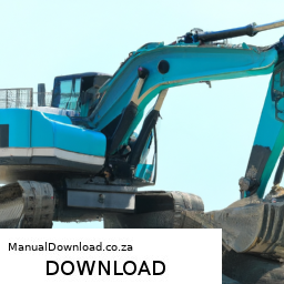
 and a solvent to clean the
 and place jack stands securely under the frame to support it.
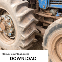
 and gaskets before reattaching the housing cover.
 and eye protection.
 and consult the manual for detailed
 and
and 
 and understand the entire process of replacing the strut mount on the KOMATSU PC27MR-3, PC30MR-3, or PC35MR-3 excavator.
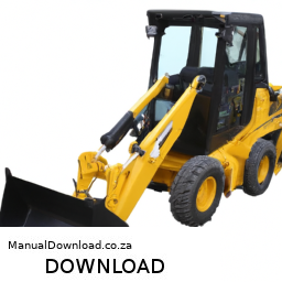
 and seated in its mounts.