Certainly! click here for more details on the download manual…..
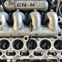
- IN GOD – How to change Fuel Filters & reset computer for CX160D Case Track hoe CX160D Case Tr… This Video will show how the reset the computer too after you have changed the Fuel Filters the CX160D Case Track hoe.
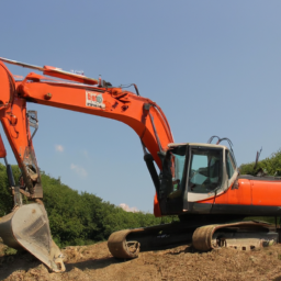
- 2004 CASE CX130 2004 CASE CX130 for sale on equipmenttrader.com: …
Here’s a step-by-step guide to checking the engine light on a Case CX130, CX160, or CX180 Excavator, presented in reverse order:
### 6. **Consult the Manual**
– Refer to the operator’s manual specific to your Case excavator model for troubleshooting steps and error code definitions.
### 5. **Clear Codes (if necessary)**
– If you have resolved the issue, you may want to clear any trouble codes using a diagnostic tool to reset the check engine light.
### 4. **Read Diagnostic Codes**
– Use an appropriate diagnostic tool to connect to the excavator’s onboard diagnostic system.
– Retrieve any stored diagnostic trouble codes (DTCs) that can provide insight into the issue causing the check engine light.
### 3. **Inspect for Obvious Issues**
– Perform a visual inspection of the engine compartment and surrounding components for any obvious signs of trouble, such as loose or damaged wires, leaks, or unusual sounds.
### 2. **Turn on the Ignition**
– Without starting the engine, turn the ignition key to the “On” position. Observe whether the check engine light illuminates and stays on momentarily as part of the self-test.
### 1. **Start the Engine**
– Start the excavator’s engine and observe the check engine light. If it remains lit after the initial self-test, further investigation is required.
By following these steps in reverse order, you can efficiently identify and address the issue related to the check engine light on your Case excavator.
The Gear selector, also known as the Gear shift or transmission lever, is a crucial component in both manual and automatic vehicles that allows the driver to select the appropriate Gear for the desired speed and power. Its primary function is to engage and disengage the transmission gears, enabling the car to operate efficiently across various driving conditions. In manual vehicles, the Gear selector is typically a stick or lever that the driver moves through a series of defined positions—often labeled with numbers indicating the gears (1 through 5 or 6) and a reverse gear. This type of selector requires the driver to coordinate the use of the clutch pedal, allowing for smooth transitions between gears while managing engine speed and power output.
In automatic vehicles, the Gear selector functions differently. It often incorporates a more complex mechanism that automatically adjusts the gears based on the vehicle’s speed and acceleration needs. The driver can select different modes, such as “Park,” “Reverse,” “Neutral,” and “Drive,” each serving distinct purposes. Advanced automatic systems may also include additional settings such as “Sport” for performance driving or “Eco” for fuel efficiency. With the advent of modern technology, some vehicles now feature electronic Gear selectors, which rely on buttons or touchscreens instead of traditional levers, providing a sleeker design and potentially quicker Gear changes. Overall, the Gear selector plays a fundamental role in vehicle operation, influencing performance, safety, and driver convenience.
 and function.
 and Remove Equipment**
 tands and lower the excavator back to the
 and test the gear shifting under operational conditions.
 and prevents future issues.
 and let it run for a few minutes. Check for any leaks around the new fuel filter and connections.
 and
and 
 and ensuring the machine is stable during the procedure.
 and hand-tighten the