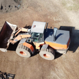
Download New Holland CL30, CL40 Operators Manual –

online
Adjusting the gear selector cable on a Holland CL30 or CL40 involves several steps. click here for more details on the download manual…..


    Rewiring a Skid Steer Loader – Rust Bucket Rehab Ford CL340 Rewiring our Skid Steer Ford CL340 Restoration, Charlie works on rewiring the electrical components of the Skid Steer.

    Rewiring a Skid Steer Loader – Rust Bucket Rehab Ford CL340 Rewiring our Skid Steer Ford CL340 Restoration, Charlie works on rewiring the electrical components of the Skid Steer.

Below is a step-by-step guide presented in reverse order:

### Step 6: Reassemble and Test
– **Reconnect Battery**: If you disconnected the battery, reconnect it.
– **Test the Gear Selector**: Start the machine and test the gear selector to ensure it shifts smoothly through all gears.
– **Inspect for Proper Operation**: Check that the gear selection aligns with the actual gear engagement and that there are no unusual sounds or resistance.

### Step 5: Final Adjustments
– **Fine-Tune the Cable**: If needed, make minor adjustments to the cable tension to achieve smooth operation. Ensure that the cable is neither too tight nor too loose.
– **Secure the Adjustments**: Ensure that all fasteners are tightened securely, and the cable is held in place without any slack.

### Step 4: Secure the Cable
– **Tighten the Cable Anchor**: Once the desired adjustment is made, tighten the anchor points to secure the cable in place.
– **Check Cable Routing**: Ensure that the cable is routed correctly and does not interfere with any moving parts.

### Step 3: Adjust the Cable Tension
– **Locate the Adjustment Point**: identify the adjustment point on the cable, usually near the gear selector mechanism.
– **Loosen the Lock Nut**: Use the appropriate tool to loosen the lock nut on the adjustment point.
– **Adjust the Cable Length**: Turn the adjustment screw to increase or decrease the cable length, which adjusts the tension. Make small adjustments and check often.

### Step 2: Access the Gear Selector Cable
– **Remove Covers**: If necessary, remove any panels or covers obstructing access to the gear selector cable.
– **Locate the Cable**: identify the gear selector cable and its connection points at both the gear shifterdownload Holland CL30 CL40 s workshop manual and the transmission.

### Step 1: Prepare for Adjustment
– **Safety First**: Ensure the machine is on a flat surface, and engage the parking brake. Turn off the engine and remove the key.
– **Gather Tools**: Collect the necessary tools, such as wrenches, pliers, and a socket set, before starting the adjustment process.

By following these steps in reverse order, you can successfully adjust the gear selector cable on a Holland CL30 or CL40. Always refer to the manufacturer’s manual for specific details and safety precautions.
The glove box, also known as a glove compartment, is a storage compartment located in the dashboard of a vehicle, typically in front of the front passenger seat. Its primary purpose is to provide a convenient space for storing various items that drivers and passengers may need while on the road. The glove box is usually accessed by opening a hinged door, which may be equipped with a latch or a locking mechanism to secure its contents.

Historically, the term “glove box” originated from its initial purpose of storing driving gloves, which were commonly worn by drivers in the early 20th century. However, over time, the use of the glove box has evolved to accommodate a range of items, including vehicle registration documents, insurance papers, owner’s manuals, maps, first-aid kits, sunglasses, and personal items such as snacks or small tools.

In modern vehicles, glove boxes may also feature additional amenities such as built-in lights, cooling functions, or even usb ports for charging electronic devices. The design and size of glove boxes can vary significantly between different car models, reflecting the manufacturer’s approach to interior space utilization. Overall, the glove box serves as an essential component of vehicle ergonomics, enhancing driver convenience and organization while contributing to a clutter-free cabin environment.

Download Daewoo Doosan DL350 Service Manual –

get
Replacing the drive belt on a Daewoo Doosan DL350 wheel loader requires careful attention to detail and adherence to safety protocols. click here for more details on the download manual…..


    How Doosan's Combination Transmission Works in the DL420 CVT Wheel Loader Combination transmission allows machine to run in either hydrostatic or traditional automatic mode when it’s most efficient for a …

    Wheel Loaders Auto Shutdown | Doosan Equipment Europe Wheel Loaders engine auto shutdown : fuel consumption saving.

Below is a step-by-step guide outlining the process, including detailed descriptions of each component involved.

### Tools and Materials Needed:
1. **Tools:**
– Socket set (including metric sockets)
– Wrenches (metric)
– Torque wrench
screwdrivers (flathead and Phillips)
– Pliers
– Belt tension gauge (optional)
– Jack stands (if needed)

2. **Materials:**
– Replacement drive belt (ensure it matches the OEM specifications)
– Belt dressing (optional)
– Lubricant (for any moving parts as necessary)

### Safety Precautions:
– **Personal protective Equipment (PPE):** Wear safety goggles, gloves, and steel-toed boots.
– **Work Area:** Ensure the work area is clean and well-lit.
– **Stability:** Make sure the machine is on a flat surface and use wheel chocks.

### Step-by-Step Drive Belt Replacement:

#### 1. **Preparation:**
– **Turn Off the Engine:** Ensure the engine is off and the key is removed from the ignition.
– **Disconnect the Battery:** Disconnect the negative terminal of the battery to prevent any electrical issues.

#### 2. **Access the Drive Belt:**
– **Locate the Drive Belt:** The drive belt is typically found near the engine compartment, connected to the alternator, water pump, and other accessories.
– **Remove Any Covers:** If there are protective covers or shields over the engine compartment, remove them using the appropriate tools (screws or bolts).

#### 3. **Inspect Existing Components:**
– **Visual Inspection:** Check for any wear on the drive belt, pulleys, and tensioners. Look for cracks, fraying, or glazing on the belt.
– **Check Tensioner:** The tensioner maintains the proper tension on the belt. Ensure it’s functioning correctly.

#### 4. **Remove the Old Drive Belt:**
– **Loosen the Tensioner:** Use a wrench or socket to release tension on the belt by rotating the tensioner pulley. This may involve either loosening a bolt or using a ratchet to pivot the tensioner.
– **Slide Off the Belt:** With the tension released, carefully remove the belt from the pulleys. Note how the belt is routed for installation of the new belt.

#### 5. **Install the New Drive Belt:**
– **Route the New Belt:** Following the belt routing diagram (often found on a sticker near the engine), route the new belt over the appropriate pulleys. Ensure it is seated properly in the grooves.
– **Adjust Tension:** If you have a manual tensioner, use the wrench to apply tension again. If it’s automatic, ensure it is engaging correctly. If using a belt tension gauge, adjust to the specified tension.

#### 6. **Recheck All Connections:**
– **Inspect Pulleys:** Before closing everything up, inspect all pulleys for any debris or damage.
– **Check Alignment:** Ensure that the belt is properly aligned within the pulleys.

#### 7. **Reattach Covers:**
– If you removed any covers or shields, reattach them securely using the original screws or bolts.

#### 8. **Reconnect the Battery:**
– Reconnect the negative terminal of the battery.

#### 9. **Start the Engine:**
– **Run the Engine:** start the enginedownload Daewoo Doosan DL350 workshop manual and let it idle for a few minutes. Listen for any unusual noises and observe the belt in operation to ensure it is functioning correctly.
– **Check for Slippage:** Ensure that the belt is not slipping off the pulleys.

#### 10. **Final Inspection:**
– After running the engine, turn it off and do a final inspection of the belt and pulleys.
– **Check Tension Again:** If necessary, recheck the tension of the belt after a short run.

### Conclusion:
The replacement of the drive belt on a Daewoo Doosan DL350 is a straightforward process if safety precautions are observed and instructions are followed carefully. Always refer to the operation and service manual for any model-specific details or torque specifications. Regular maintenance will ensure the longevity and reliability of your equipment.
The Manifold Absolute Pressure (MAP) sensor is a critical component in modern internal combustion engines, playing a vital role in optimizing engine performance and efficiency. Positioned within the intake manifold, the MAP sensor measures the absolute pressure of the air entering the engine. This information is crucial for the engine control unit (ECU) as it helps determine the optimal air-fuel mixture necessary for combustion.

The MAP sensor operates by utilizing a diaphragm that responds to changes in manifold pressure. When the engine is running, the pressure in the intake manifold varies based on engine load, throttle position, and altitude. The sensor converts these pressure changes into an electrical signal that is sent to the ECU. The ecu interprets this data, along with inputs from other sensors (such as the throttle position sensor and air temperature sensor), to calculate the appropriate amount of fuel to inject into the combustion chambers.

By accurately gauging the air pressure, the MAP sensor helps the ecu adjust the fuel delivery, ignition timing, and other parameters, enhancing engine performance, fuel economy, and emissions control. A malfunctioning MAP sensor can lead to various issues, including poor engine performance, increased fuel consumption, and elevated emissions, making it essential for vehicle maintenance and diagnostics. Overall, the MAP sensor is integral to modern engine management systems, ensuring that vehicles run efficiently and reliably.

Download DAEWOO DOOSAN MEGA 200- Wheeled Loader Service Parts Catalogue Manual –

online
Performing a transmission fluid flush on a Daewoo Doosan Mega 200 Wheeled Loader involves several steps that should be executed in reverse order for clarity. click here for more details on the download manual…..


    DOOSAN MEGA 250, 2006 wheeled loader DOOSAN MEGA 250V, Year: 2006, Hours: 945 only, in top condition for sale. Ask for an offer: info@ikran.eu.

    Dead Doosan Excavator Forced To Work | Excavator Working Video Welcome to our new Excavator video of Handicapped Excavator working in Mining. Excavators are massive and used for mass …

Here’s a detailed guide in reverse order:

### 8. Final Steps
– **Reconnect the Battery**: After ensuring everything is secure and all connections are checked, reconnect the battery.
– **Check Fluid Level**: start the engine and allow it to idle for a few minutes. With the engine running, check the transmission fluid level using the dipstick or level indicator. Add more fluid if necessary.

### 7. Clean Up
– **Dispose of Old Fluid**: Properly dispose of the old transmission fluid and any used filters according to local regulations.
– **Store Tools**: Gather and store all tools and equipment used during the process.

### 6. Replace the Transmission Filter (if applicable)
– **Install New Filter**: If your model has a transmission filter, remove the old filter and install the new one according to manufacturer specifications.
– **Secure Filter**: Ensure the filter is properly sealed and secured to prevent leaks.

### 5. Drain Old Transmission Fluid
– **Remove Drain Plug**: Place a drain pan under the transmission and remove the drain plug to allow the old fluid to drain completely.
– **Wait for Complete Drainage**: allow sufficient time for all fluid to drain out.

### 4. Flush the Transmission
– **Add Flush Solution**: If using a transmission flush machine, follow the manufacturer’s instructions to add the flush solution. If doing it manually, you might run the vehicle for a short time while the fluid circulates.
– **Run Engine**: If doing a manual flush, start the engine and let it run for a few minutes to circulate the flush solution.

### 3. Prepare for the Flush
– **Gather Necessary Tools and Materials**: Have the required tools, new transmission fluid, a new filter (if applicable), a drain pan, and any flush solutions ready.
– **Safety Precautions**: Ensure the loader is parked on a flat surface, and the engine is cool. Use proper safety equipment, such as gloves and goggles.

### 2. Access the Transmission
– **Lift the Loader**: If necessary, lift the loader using jacks or ramps to gain access to the undercarriage.
– **Locate the Transmission Components**: Identify the transmission fluid drain plug and filter location (if applicable).

### 1. Prepare the Work Area
– **Ensure Adequate Space**: Make sure you have enough room to work around the loader.
– **Safety Measures**: Ensure the area is well-ventilateddownload DAEWOO DOOSAN MEGA 200 Wheeled Loader ue workshop manual and that any hazards are cleared.

### Important Notes
– Always refer to the specific operator’s manual for your Daewoo Doosan Mega 200 Wheeled Loader for any manufacturer-specific procedures or recommendations.
– It’s crucial to use the correct type of transmission fluid specified for your loader to prevent damage.
– If you’re not comfortable performing this procedure, consider hiring a qualified mechanic or technician.

Following these steps in reverse order will help ensure a comprehensive understanding of the process involved in flushing the transmission fluid.
A brake light bulb is a crucial component of a vehicle’s lighting system, specifically designed to signal when a driver is applying the brakes. Located at the rear of the vehicle, brake light bulbs serve an essential safety function by alerting other drivers to the vehicle’s deceleration or stopping action. This communication is vital for preventing rear-end collisions, as it provides a clear indication of the vehicle’s intentions to those following behind.

Brake light bulbs come in various types, including incandescent, halogen, and LED options. Incandescent bulbs, typically the traditional choice, emit light through a filament that heats up when electricity passes through it. Halogen bulbs are a more advanced version of incandescent bulbs, offering improved brightness and longevity. LED brake light bulbs have gained popularity due to their energy efficiency, longer lifespan, and faster response time when activated. This means they illuminate more quickly than traditional bulbs, providing a more immediate warning to drivers behind.

The installation of brake light bulbs is generally straightforward, with most vehicles allowing easy access to the light housing. However, regular maintenance is essential, as burnt-out bulbs can go unnoticed, compromising safety. Therefore, drivers should routinely check their brake lights to ensure they are functioning correctly, contributing to overall road safety for everyone.

Download Hyundai Wheel Loaders HL757-7 Service Manual –

australia
Replacing the lower control arm on a Hyundai HL757-7 wheel loader can seem daunting, especially if you have limited mechanical experience. click here for more details on the download manual…..


      Hyundai HL760-9 Wheel Loader

    However, with the right guidance and some patience, you can tackle this job. Here’s a step-by-step explanation of how to do it:

    ### Tools and Materials Needed:
    – Safety equipment (gloves, goggles, etc.)
    – Jack and jack stands
    wrenches and sockets (specific sizes will depend on your vehicle)
    – Torque wrench
    – Hammer
    – Pry bar
    – Replacement lower control arm
    – Lubricant (like grease)

    ### Steps for Lower Control Arm Replacement:

    1. **Safety First**:
    – Make sure the wheel loader is on a flat surface.
    – Engage the parking brake and turn off the engine.
    – Wear safety gloves and goggles for protection.

    2. **Lift the Wheel Loader**:
    – Use a jack to lift the front end of the wheel loader.
    – Place jack stands securely under the frame to support the vehicle. Never work under a vehicle supported only by a jack.

    3. **Remove the Wheel**:
    – Use a wrench or socket to loosen and remove the lug nuts on the wheel you’re working on.
    – Carefully take the wheel off and set it aside.

    4. **Locate the Lower Control Arm**:
    – The lower control arm is a metal arm that connects the frame of the wheel loader to the wheel hub. It helps with the wheel’s movement and stability.

    5. **Disconnect the Lower Control Arm**:
    – Look for bolts connecting the lower control arm to the frame and the wheel hub. Use the appropriate socket or wrench to remove these bolts.
    – If the bolts are tight, you may need to use a hammer to gently tap them out or apply some lubricant to help loosen them.

    6. **Remove the Old Control Arm**:
    – Once the bolts are removed, the lower control arm should come free. You may need to use a pry bar to help separate it from the vehicle if it’s stuck.

    7. **Install the New Control Arm**:
    – Take your new lower control arm and position it where the old one was removed.
    – Align it with the mounting points on the frame and the wheel hub.

    8. **Reconnect the Bolts**:
    – Insert and hand-tighten the bolts to hold the new control arm in place.
    – Once all bolts are in position, use your torque wrench to tighten them to the manufacturer’s specifications. this information can usually be found in the service manual.

    9. **Replace the Wheel**:
    – Reattach the wheel, making sure it is aligned properly.
    – Hand-tighten the lug nuts,download Hyundai Wheel Loaders HL757 7 workshop manual and then lower the wheel loader back to the ground before fully tightening the lug nuts in a crisscross pattern.

    10. **Final Checks**:
    – Ensure everything is securely fastened and that there are no leftover parts.
    – Check for any unusual sounds or movements when you first drive the wheel loader after the repair.

    ### Conclusion:
    Replacing a lower control arm can be challenging, but by following these steps carefully, you can complete the task with confidence. If you encounter any issues or feel unsure at any point, don’t hesitate to consult a more experienced mechanic or refer to the vehicle’s service manual for specific details related to your model. Always prioritize safety and double-check your work before putting the wheel loader back into operation.
    The oil drain gasket, also commonly referred to as the oil pan gasket, is an essential component of an internal combustion engine’s lubrication system. Its primary function is to create a seal between the oil pan and the engine block, preventing the engine oil from leaking out. this gasket is typically made from materials like rubber, silicone, or composite materials that can withstand the high temperatures and pressures found in an engine environment.

    The oil drain gasket plays a crucial role in maintaining the integrity of the engine’s lubrication system. A properly sealed oil pan ensures that the engine oil remains contained, allowing it to efficiently lubricate the moving parts of the engine, reduce friction, and dissipate heat. Over time, due to factors like age, heat cycling, and exposure to oil, the gasket can deteriorate, leading to leaks. An oil leak can result in a decrease in oil levels, which can cause engine wear, overheating, and potentially catastrophic engine failure if not addressed promptly.

    Replacing a worn or damaged oil drain gasket is a relatively straightforward maintenance task, yet it is vital for the overall health of the engine. Regular inspections and maintenance can help identify potential issues with the gasket, ensuring optimal engine performance and longevity. In summary, the oil drain gasket is a small but critical component that plays a vital role in the effective operation of an engine’s lubrication system.

    Download Liebherr L556 – 1288 Wheel loader Service Repair Workshop Manual –

    book store
    Repairing the torque converter clutch on a Liebherr L556 1288 wheel loader can be a complex task, especially for someone with little mechanical experience. click here for more details on the download manual…..


      How To Replace Rear Hub Bearing Assemblies – Dodge Neon (Andy’s Garage: Episode – 403) In this video, Andy Phillips shows step by step how to replace the rear hub bearing assembly on a Dodge Neon. Replacing a hub …

      LIEBHERR L556 shovel – wheel loader www.tijs.nl €72500 Brand: LIEBHERR Type: L556 Year of construction: 2016 Hours: 8177 SN number: 1288-41621 – additional; …

    However, I’ll break it down into simpler terms so you can understand the general process. Please remember that it’s always best to consult the operator’s manual or a professional mechanic for specific guidance.

    ### What is a Torque Converter and a Clutch?

    1. **Torque Converter**: This is a component in your wheel loader’s transmission that helps to transfer power from the engine to the wheels. It allows the vehicle to move without stalling and provides a smoother driving experience.

    2. **Clutch**: The torque converter has a clutch that locks the converter to the engine at higher speeds to improve efficiency. Sometimes, this clutch can fail, causing issues like slipping or overheating.

    ### Basic Steps for Repairing the Torque Converter Clutch

    #### 1. **Safety First**
    – Ensure that the wheel loader is turned off, parked on a flat surface, and the key is removed.
    – Wear safety goggles and gloves to protect yourself.

    #### 2. **Gather Tools and Materials**
    – You will need basic tools such as wrenches, sockets, screwdrivers, and possibly a jack and jack stands.
    – Replacement parts like the torque converter clutch or seals may also be needed.

    #### 3. **Accessing the Torque Converter**
    – **Remove the access Panel**: Depending on the design of the Liebherr L556, you may need to remove the cover or access panel to get to the torque converter. This usually involves unscrewing a few bolts.
    – **Locate the Torque Converter**: It will be near the engine and connected to the transmission.

    #### 4. **Disconnecting Components**
    – **Fluid Lines**: Carefully disconnect any hydraulic lines connected to the torque converter. Be prepared for some hydraulic fluid to spill, so have a container ready to catch it.
    – **Electrical Connections**: If there are any electrical connectors, disconnect them as well.

    #### 5. **Removing the Torque Converter**
    – **Unbolt the Torque Converter**: There will be bolts holding the torque converter in place. Use the appropriate socket to remove them.
    – **Carefully Pull It Out**: Once unbolted, gently pull the torque converter away from the engine. Be cautious, as it can be heavy.

    #### 6. **Inspecting and Repairing**
    – **Check for Damage**: Look for any signs of wear or damage on the clutch and torque converter. If the clutch is worn out, it will need to be replaced.
    – **Replace the Clutch**: If necessary, remove the old clutch and install a new one according to the instructions provided with the replacement part.

    #### 7. **Reinstalling the Torque Converter**
    – **Aligndownload Liebherr L556 1288 Wheel loader workshop manual and Insert**: Carefully align the torque converter back into place and push it towards the engine.
    – **Bolt It Back**: Reattach the bolts to secure the torque converter.

    #### 8. **Reconnecting Components**
    – **Reconnect Hydraulic Lines**: Reattach any fluid lines and tighten them securely.
    – **Reconnect Electrical Connections**: If you disconnected any electrical components, reconnect them.

    #### 9. **Final Steps**
    – **Replace the access Panel**: Once everything is back in place, replace the access panel and secure it with screws.
    – **Refill Fluids**: If any hydraulic fluid was lost, refill it to the appropriate level.
    – **Test the Loader**: start the wheel loader and test the operation of the torque converter clutch to ensure it’s working properly.

    ### Conclusion

    Repairing the torque converter clutch on a Liebherr L556 wheel loader can be challenging without mechanical experience. Always prioritize safety and consider seeking help from a professional mechanic if you’re uncertain about any step. Additionally, referring to the manufacturer’s service manual will provide specific details tailored to your machine.
    A tire is a crucial component of a vehicle, serving as the interface between the car and the road. Constructed from layers of rubber, fabric, and steel, tires are designed to provide traction, stability, and support for the weight of the vehicle. They come in various types and sizes, tailored to different driving conditions and vehicle requirements, including passenger cars, trucks, and specialized vehicles.

    The primary function of a tire is to provide grip on the road surface, allowing for safe acceleration, braking, and cornering. The tread pattern on the tire plays a significant role in this aspect, as it is engineered to channel water away, reducing the risk of hydroplaning and enhancing traction in wet conditions. Tires are also designed to absorb shocks from bumps and irregularities in the road, contributing to a smoother ride for passengers.

    Tires are categorized into various types such as all-season, winter, and performance tires, each optimized for specific driving conditions. Regular maintenance, including checking air pressure and tread depth, is essential for tire longevity and vehicle safety. Additionally, tire technology has evolved significantly, with advancements in materials and design improving fuel efficiency, reducing road noise, and enhancing performance. Overall, tires are integral to vehicle safety and performance, influencing everything from handling to fuel economy.

    Download 2011 Terex Wheel Loader TL100 Operating Manual –

    online
    Replacing the clutch release bearing on a Terex Wheel Loader TL100 involves several detailed steps and requires specific tools and equipment. click here for more details on the download manual…..


      Terex TL100 Compact Loading Shovel Terex TL100 Shovel. Dec 2012 (62). 3022 hours. 405/70- x 20 bibload style tyres – 20%. RDS weighlog. Deutz 55KW (75HP …

      Below is a comprehensive guide to assist you in the process.

      – **Preparation and Safety**
      – **Personal Protective Equipment (PPE):** Ensure you are wearing appropriate PPE, including gloves, safety glasses, and steel-toed boots.
      – **Work Area:** Clear the workspace and ensure it is well-lit and free of hazards.
      – **Owner’s Manual:** Have the TL100 owner’s manual on hand for specific instructions and torque specifications.

      – **Tools and Equipment Required**
      – **Basic Hand Tools:**
      – **Socket Set:** Metric and standard sockets for various bolts.
      – **Wrenches:** A set of open-end and box-end wrenches for different sizes.
      – **Screwdrivers:** Flathead and Phillips screwdrivers for various fasteners.
      – **Specialized Tools:**
      – **Clutch Alignment Tool:** To ensure the clutch is properly aligned during reassembly.
      – **Bearing Puller or Slide Hammer:** For removing the old release bearing.
      – **Torque Wrench:** For tightening bolts to manufacturer specifications.
      – **Pry Bar:** To help separate components when necessary.
      – **Lifting Equipment:**
      – **Jack and Jack Stands:** To lift the loader safely.
      – **Engine Hoist or A-Frame:** If the Engine needs to be removed for access.

      – **Disconnecting the Battery**
      – Disconnect the negative terminal of the battery to prevent electrical shorts and ensure safety while working.

      – **Removing the Transmission**
      – **Accessing the Transmission:**
      – Depending on the design, you may need to remove the Engine assembly or access the transmission through the underside of the loader.
      raise the loader using a jack and secure with jack stands to ensure it is stable.
      – **Disconnecting Components:**
      – Remove any components that obstruct access to the transmission, such as the driveshaft, exhaust system, or hydraulic lines.
      – Label and store bolts and parts in a clear manner for reassembly.
      – **Unbolting the Transmission:**
      – Carefully unbolt the transmission from the engine, noting the locations of each bolt.
      – Use a bearing puller or slide hammer to gently pull the transmission away from the engine.

      – **Accessing the clutch Assembly**
      – Once the transmission is removed, locate the clutch assembly.
      – Inspect the clutch housing for any wear or damage that may require further attention.

      – **Removing the Old clutch Release Bearing**
      – **Release bearing Retainer:** If there is a retainer holding the release bearing in place, remove it using appropriate tools.
      – **Extracting the Bearing:** Use the bearing puller to carefully remove the old clutch release bearing from the clutch fork or housing.

      – **Installing the New clutch Release Bearing**
      – **Preparation:** Clean the area where the new bearing will be installed to remove any debris or old lubricant.
      – **Positioning the New Bearing:** Carefully install the new clutch release bearing into the clutch fork or housing, ensuring it is seated properly.
      – **Reinstall Retainer:** If applicable, reinstall the bearing retainer to secure the new bearing in place.

      – **Reassembling the clutchdownload Terex Wheel Loader TL100 workshop manual and Transmission**
      – **Aligning the Clutch:** Use the clutch alignment tool to ensure the clutch disc is correctly aligned with the flywheel.
      – **Reinstall the Transmission:** Carefully guide the transmission back into position, ensuring all alignment pins are aligned.
      – **Bolting the Transmission:** Securely bolt the transmission back to the Engine using the specified torque values from the owner’s manual.

      – **Reconnecting Components**
      – Reattach any components that were removed previously, such as the driveshaft, exhaust system, and hydraulic lines.
      – Ensure all connections are tight and secure.

      – **Final Checks**
      – **Reconnect the Battery:** Reconnect the negative terminal of the battery.
      – **Fluid Levels:** Check and fill any necessary fluids, such as transmission fluid or hydraulic fluid.
      – **Test Operation:** Start the Terex Wheel Loader and test the clutch operation. Look for any unusual noises or issues during operation.

      – **Dispose of Old Parts Properly**
      – Ensure the old release bearing and any other discarded components are disposed of according to local regulations.

      Following these steps will help you successfully replace the clutch release bearing on a Terex Wheel Loader TL100. Always refer to the specific service manual for additional details and specifications related to your model.
      A cable release is a mechanical device commonly used in photography and certain automotive applications, designed to trigger or release a function remotely without the need for direct manual interaction with the mechanism. In photography, a cable release allows photographers to take a picture without physically touching the camera, which helps minimize camera shake and results in sharper images, especially during long exposures or when using telephoto lenses. The device typically consists of a flexible cable that connects a button or lever to the camera’s shutter mechanism. When the photographer presses the button, the cable transmits the action to the camera, releasing the shutter and capturing the image.

      In automotive contexts, a cable release can refer to a mechanism that operates a variety of functions, including hood latches, trunk releases, or even emergency brake systems. This component usually consists of a pull cable that connects a handle inside the vehicle to the latch mechanism outside. When the driver pulls the handle, it pulls on the cable, which in turn releases the latch, allowing the hood or trunk to open. The cable release system is designed for ease of use and accessibility, enabling quick access to essential components of the vehicle without the need for additional tools.

      Overall, the cable release is a simple yet effective tool that enhances functionality and user experience in both photography and automotive applications.

      Download Case 521E Parts-

      shop
      Repairing the suspension on a Case 521E involves several steps that typically need to be performed in a specific order to ensure safety and effectiveness. click here for more details on the download manual…..


        How to: Operate A Wheel Loader Quick video on how to Operate a wheel loader like I said in the video there are other switches to control functions to control things …

        Toro 521 snow blower recoil starter install and carburetor clean I purchased the snow blower for cheap and begin to diagnose it. After installing the recoil starter and cleaning the carburetor I …

      Here’s a reverse order of the suspension repair process:

      ### 7. Reassemble the Components
      – **Reattach Wheels**: If you removed the wheels, reattach them and ensure they are torqued to the manufacturer’s specifications.
      – **Reconnect any removed components**: This includes any brackets, shields, or covers that were taken off during the repair process.

      ### 6. Test the Suspension
      – **Check for proper operation**: Once everything is reassembled, operate the machine to ensure the suspension is functioning correctly. Look for any unusual noises or signs of misalignment.
      – **Inspect for leaks**: If hydraulic components were involved, check for leaks.

      ### 5. Install New Components
      – **Install new parts**: Replace any worn-out components, such as bushings, springs, or shocks, ensuring they are properly seated and secured.
      – **Torque specifications**: Use a torque wrench to tighten bolts to the manufacturer’s specifications.

      ### 4. Remove Old Components
      – **Take out damaged parts**: Carefully remove any worn or damaged suspension components. This may involve unbolting shocks, springs, or control arms.
      – **Mark and label components**: If necessary, mark the location of components for easier reinstallation.

      ### 3. Lift the Machine
      – **Use a hydraulic lift or jack**: Safely elevate the machine to access the suspension components. Make sure to use jack stands for safety.

      ### 2. Prepare the Work Area
      – **Gather tools and parts**: Ensure you have all necessary tools (wrenches, sockets, etc.) and replacement parts ready.
      – **Clean the area**: Remove any debris or obstructions from the work area to ensure a safe working environment.

      ### 1. Safety Precautions
      – **Wear safety gear**: Use gloves, goggles, and other appropriate safety equipment.
      – **Ensure stability**: Make sure the machine is on level grounddownload Case 521E Parts workshop manual and stable before starting any work.

      By following these steps in reverse, you can effectively perform a suspension repair on a Case 521E loader. Always consult the machine’s service manual for specific instructions and torque specifications related to your model.
      Carpet, as a component of an automobile’s interior, plays a crucial role in enhancing both the aesthetic appeal and functionality of the vehicle. primarily made from synthetic fibers like nylon, polyester, or polypropylene, car carpets serve several important purposes. They provide a soft, comfortable surface for passengers, enhancing the overall driving experience. The carpet helps to absorb sound, reducing noise levels inside the cabin and contributing to a quieter ride, which is particularly valuable in luxury vehicles.

      In addition to comfort and sound insulation, car carpets also contribute to safety. They are designed with anti-slip properties to help keep passengers stable while entering or exiting the vehicle. Many modern carpets include additional padding or insulation layers that not only absorb vibrations but also add thermal insulation, which helps maintain a comfortable temperature inside the vehicle.

      Moreover, car carpets are typically designed to be durable and resistant to wear and tear from daily use. They can withstand spills, dirt, and the wear from footwear, making them easier to clean and maintain. Many vehicles come equipped with removable carpet mats to provide additional protection and ease of cleaning. Overall, car carpets are an essential component that combines functionality, comfort, and aesthetics, significantly impacting the driving experience and interior ambiance.

      Download Hyundai HL730-7A,HL730TM-7A Wheel Loader Factory Service Repair Manual-

      get
      Performing a CV joint replacement on a Hyundai HL730 7A Wheel Loader involves several detailed steps. click here for more details on the download manual…..


        Hyundai HL730-9A Wheel Loader Hyundai HL730-9A Wheel Loader, EROPS, diesel engine, heat, air conditioning, Am/Fm radio, 8′ bucket, 17.5R25 tires, operating …

        Ask The Experts: How To Operate a Hyundai HL700 Series Wheel Loader We go over what you should know about Hyundai wheel loader basic operation.

      While I can’t provide a manual, I can summarize the process in reverse order for clarity. Please ensure that you have the proper tools and safety equipment before beginning the procedure.

      ### Reverse Order Steps for CV Joint Replacement:

      1. **Reinstall the Wheel and Lower the Loader**:
      – Tighten the wheel lug nuts to the manufacturer’s specifications.
      – Lower the loader back onto the ground.

      2. **Reconnect the Steering Assembly**:
      – Reattach any steering components that were disconnected during the CV joint removal.

      3. **Reinstall the CV Joint**:
      – Align the new CV joint with the axle and push it into place.
      – Ensure that it is properly seated and the retaining clips are secure.

      4. **Install the Axle Nut**:
      – Place the axle nut onto the CV joint and tighten it to the specified torque.

      5. **Reattach the Brake Components**:
      If the brake caliper was removed, reinstall it and ensure it is properly secured.

      6. **Reconnect Any Disconnect Components**:
      – Reattach any suspension or transmission components that may have been removed for access.

      7. **Inspect and Clean**:
      – Before final assembly, inspect the surrounding components for wear or damage.
      – Clean any debris and grease from the area.

      8. **Remove the Old CV Joint**:
      – Use appropriate tools to disconnect the old CV joint from the axle and the wheel assembly.

      9. **Lift the Loader**:
      – Use a hydraulic jack to lift the loader safely and secure it with jack stands.

      10. **Prepare the work Area**:
      – Gather all necessary tools including wrenches, sockets, and a torque wrench.
      – Ensure the loader is on a flat surface and the wheels are chocked for safety.

      ### Additional Tips:
      – Always refer to the specific service manual for the Hyundai HL730 7A for detailed torque specifications and any model-specific steps.
      – It’s advisable to have a second person assist with heavy components.
      – Wear safety gear such as glovesdownload Hyundai HL730 7A HL730TM 7A Wheel Loader Manual workshop manual and goggles.

      This reverse order guide should help you visualize the steps for CV joint replacement. Always prioritize safety and consult a professional If uncertain about any step in the process.
      The brake light switch is a crucial component of a vehicle’s braking system, playing a vital role in ensuring both safety and functionality. Located usually near the brake pedal, this switch is activated when the driver presses the brake pedal. Its primary function is to complete an electrical circuit that activates the brake lights, signaling to other drivers that the vehicle is slowing down or stopping. This is essential for road safety, as it alerts following vehicles to the driver’s intentions, helping to prevent rear-end collisions.

      Brake light switches are typically designed to be highly reliable, as they are critical for safe driving. They can be mechanical or electronic, with mechanical switches relying on physical movement to engage, while electronic switches may use sensors to detect pedal movement. In some modern vehicles, the brake light switch can also interact with other systems, such as cruise control, to disengage when the brakes are applied.

      Failure of the brake light switch can lead to a range of issues, including malfunctioning brake lights, which can result in traffic violations or accidents. Symptoms of a failing brake light switch may include the brake lights remaining illuminated even when the pedal is not pressed, or the brake lights not illuminating at all. Regular inspection and timely replacement of this component are essential for maintaining vehicle safety and functionality.

      Download Fiat Kobelco Compact LINE W80 Mini Wheel Loaders* Factory Service / Repair/ Workshop Manual ! –

      books
      Repairing the alternator on a Fiat Kobelco Compact LINE W80 Mini Wheel Loader involves several steps. click here for more details on the download manual…..


        Diesel Injection Pump (IN LINE 6 CYLINDER HIGHPRESSURE DIESELPUMP) #injectionpump #fuelpump #dies… Diesel Injection Pump (IN LINE 6 CYLINDER HIGHPRESSURE DIESELPUMP) #injectionpump #fuelpump #diesel #dieselpump …

      Below is a detailed guide, broken down into bullet points, outlining the tools needed and the step-by-step process for the repair.

      ### Tools Required:
      – **Socket Wrench Set**: For loosening and tightening various bolts and nuts on the alternator.
      – **Torque Wrench**: To ensure that bolts are tightened to the manufacturer’s specifications.
      – **Screwdrivers (Flathead and Phillips)**: For removing any covers or panels that may obstruct access to the alternator.
      – **Pliers**: To help with disconnecting and securing electrical connectors.
      – **Wire Brush or Sandpaper**: For cleaning the electrical connections and the mounting area.
      – **Multimeter**: To test the output voltage of the alternator and diagnose issues.
      – **Belt tension Gauge**: To ensure proper tension on the alternator belt (if applicable).
      – **Replacement Parts**: New alternator or alternator components (if needed), such as brushes or diodes.
      – **Safety Gear**: Gloves, safety glasses, and possibly a hard hat.

      ### Steps to Repair the Alternator:

      – **Safety First**:
      ensure the equipment is turned off and parked on a level surface.
      – Engage the parking brake and disconnect the battery to avoid any electrical shorts.

      – **Access the Alternator**:
      – Remove any covers or panels that may obstruct access to the alternator. Use screwdrivers to take out screws or bolts securing these components.
      – Locate the alternator, typically mounted on the engine block.

      – **Disconnect electrical Connections**:
      – Carefully disconnect the wiring harness from the alternator. Use pliers to gently pull on the connectors without damaging them.
      – Remove the positive and negative battery cables if they are still connected to prevent any electrical hazard.

      – **Remove the Alternator Belt**:
      – If applicable, use a wrench to loosen the tensioner pulley and remove the belt from the alternator. ensure to note the routing of the belt for reinstallation.

      – **Unscrew the Alternator**:
      – Use a socket wrench to remove the bolts securing the alternator to its mount. Keep these bolts in a safe place for reinstallation.

      – **Inspect the Alternator**:
      – Once removed, inspect the alternator for any visible signs of wear or damage. Look for burnt-out diodes, worn brushes, or damaged bearings.
      – Use a multimeter to check the output voltage. A healthy alternator should produce around 13.5 to 14.5 volts when running.

      – **Repair or Replace**:
      – If the alternator is repairable, replace worn components such as brushes or diodes. Follow the manufacturer’s guidelines for replacement parts.
      – If the alternator is beyond repair, install the new alternator in its place. ensure the mounting holes align correctly.

      – **Reinstall the Alternator**:
      – Secure the alternator back onto its mount using the original bolts. Tighten them to the manufacturer’s specifications using a torque wrench.

      – **Reconnect the Belt**:
      – If applicable, reroute the alternator belt according to the noted configurationdownload Fiat Kobelco Compact LINE W80 Mini Wheel Loaders workshop manual and adjust the tension using the tensioner pulley. Use a belt tension gauge to ensure proper tension.

      – **Reconnect electrical Connections**:
      – Reattach the wiring harness and ensure all connections are secure. Connect the positive and negative battery cables.

      – **Test the System**:
      – Reconnect the battery and start the engine. Check the voltage output at the alternator using a multimeter to ensure it is functioning correctly.
      – Observe the alternator for any unusual noises or issues during operation.

      – **Final Checks**:
      – Replace any covers or panels removed earlier and secure them with screws or bolts.
      – Dispose of any old parts or materials safely.

      ### Conclusion:
      Following these steps will help you successfully repair the alternator on a Fiat Kobelco Compact LINE W80 Mini Wheel Loader. Always refer to the manufacturer’s service manual for specific instructions and safety guidelines tailored to your equipment.
      A wheel lock is a vital security component designed to prevent the theft of wheels and tires from vehicles. It usually consists of a specialized lug nut or bolt that requires a unique key or adapter for removal, making it nearly impossible for thieves to detach the wheels without the proper tool. Wheel locks are typically made from hardened steel, providing durability and resistance against cutting and impact tools.

      The installation of wheel locks is straightforward; they replace one or more of the standard lug nuts on each wheel. The locking mechanism is characterized by a unique pattern or shape that corresponds to a specific key. This means that even if a thief possesses a standard set of tools, they would be unable to remove the locked wheel without the corresponding key.

      In addition to enhancing security, wheel locks also serve as a visual deterrent. The presence of wheel locks can make a vehicle less attractive to potential thieves, who might opt for easier targets. While no security measure is foolproof, wheel locks significantly increase the difficulty and time required to steal wheels, thereby reducing the likelihood of theft.

      Overall, wheel locks are an essential investment for vehicle owners who want to protect their wheels and tires from theft, especially in areas where such incidents are prevalent. They offer peace of mind and contribute to the overall security strategy for personal vehicles, car dealerships, and rental agencies alike.

      Download KOMATSU WA380-1, WA420-1 Wheel Loader Operation & Maintenance Manual (S/N: 20001 and up) –

      owners manual
      Replacing a catalytic converter on a Komatsu WA380-1 or WA420-1 wheel loader can seem daunting, but with a basic understanding and the right tools, you can accomplish this task. click here for more details on the download manual…..


        Parking brake release solenoid

        2014 KOMATSU WA380-7 RUBBER TIRE LOADER For Sale https://www.machinerytrader.com/listings/other-items/for-sale/208588499?LP=MAT EROPS, NO BUCKET, 23.5R25 TIRES, …

      Below is a step-by-step guide tailored for someone with little mechanical experience.

      ### Tools and Materials Needed:
      1. **Safety Gear**: Safety glasses, gloves, and a hard hat.
      2. **Basic Tools**:
      – Wrenches (typically 10mm, 12mm, or 14mm)
      – Socket set
      – Ratchet
      – Torque wrench
      – Pliers
      – Screwdriver
      3. **New Catalytic Converter**: Make sure you have the correct model for your Komatsu WA380-1 or WA420-1.
      4. **Gasket**: For sealing the connection.
      5. **Shop Rags**: For cleaning up.

      ### Step-by-Step Replacement Process:

      #### Step 1: Safety First
      – **Park the Loader**: Ensure the loader is parked on a flat surface and the engine is off.
      – **Engage the Parking Brake**: This will prevent the machine from moving unexpectedly.
      – **Disconnect the Battery**: Disconnect the negative terminal to prevent any electrical issues while working.

      #### Step 2: Locate the Catalytic Converter
      – **Find the Exhaust System**: The catalytic converter is located along the exhaust system, usually between the engine and the muffler.
      – **Identify the Converter**: It is a cylindrical component, often covered in a heat shield.

      #### Step 3: Remove the Old Catalytic Converter
      – **Access the Converter**: Depending on the design, you might need to remove some protective covers or heat shields to reach the converter.
      – **Loosen Bolts**: Using the appropriate wrench or socket, carefully loosen the bolts securing the catalytic converter to the exhaust system. If they are rusted, you might need to apply some penetrating oil.
      – **Remove the Converter**: Once the bolts are removed, gently pull the catalytic converter away from the exhaust pipes. You might need to twist or turn it slightly to free it.

      #### Step 4: Prepare for the New Converter
      – **Clean the Area**: Use a rag to clean the exhaust pipe flanges where the new converter will attach. This helps ensure a good seal.
      – **Check Gasket**: If the old gasket is worn out, replace it with a new one.

      #### Step 5: Install the New Catalytic Converter
      – **Position the New Converter**: Align it with the exhaust pipes.
      – **Secure with Bolts**: Hand-tighten the bolts first to hold the converter in place, then use your wrench to tighten them securely. Be careful not to overtighten, as this can damage the converter or exhaust pipes.
      – **Replace Heat Shields**: If you removed any heat shields, reattach them now.

      #### Step 6: Reconnect the Battery
      – **Reconnect the Battery**: Attach the negative terminal back to the battery.

      #### Step 7: Test the Loader
      – **Start the Engine**: Turn on the loader and let it idle for a few minutes.
      – **Check for Leaks**: Listen for any unusual soundsdownload KOMATSU WA380 1 WA420 1 Wheel Loader Operation S N 1 up workshop manual and look for exhaust leaks around the catalytic converter area. If you see any leaks, you may need to tighten the bolts further.

      ### Final Tips:
      – **Consult the Owner’s Manual**: If you have access to the loader’s manual, refer to it for specific instructions or torque specifications.
      – **Seek Help if Needed**: If at any point you feel uncomfortable, don’t hesitate to ask for help from someone with more mechanical experience.

      ### Conclusion
      Replacing the catalytic converter on a Komatsu WA380-1 or WA420-1 wheel loader requires basic tools and a careful approach. By following these steps, you can complete the replacement and help ensure the machine runs efficiently and meets emission standards. Always prioritize safety and don’t hesitate to seek assistance if needed.
      A pressure plate is a crucial component in a vehicle’s clutch system, primarily found in manual transmission vehicles. Its primary role is to engage and disengage the clutch, allowing for smooth shifting between gears. The pressure plate is a metal disc that is mounted on the flywheel, and it works in conjunction with the clutch disc and release bearing.

      When the driver presses the clutch pedal, the release bearing pushes against the pressure plate, causing it to move away from the clutch disc. This disengagement allows the engine to rotate independently of the transmission, enabling the driver to shift gears without grinding or damaging the gearbox. When the pedal is released, a series of springs within the pressure plate push it back into contact with the clutch disc, re-engaging the clutch and allowing power from the engine to be transmitted to the wheels.

      The pressure plate is designed to withstand significant forces and heat generated during the engagement and disengagement process. It often features a series of springs that provide the necessary clamping force to hold the clutch disc tightly against the flywheel, ensuring efficient power transfer. Over time, however, wear and tear can lead to issues such as slipping or difficulty in shifting gears, necessitating replacement to maintain optimal vehicle performance. Understanding the role and functionality of the pressure plate is essential for diagnosing clutch-related issues and ensuring the longevity of a vehicle’s transmission system.