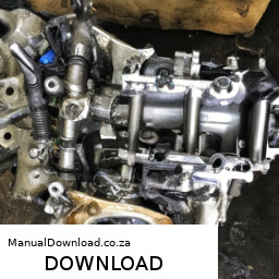
Windshield repair on a Kawasaki FH721D engine workshop may refer to a process related to repairing a damaged windshield on a vehicle or equipment that utilizes this engine. click here for more details on the download manual…..
- Kawasaki FH721D Kawasaki FH721D 25hp bench test.
- Kawasaki fh721d piston install 25hp John Deere 757
However, it seems that you might be looking for a general guide on how to perform windshield repair, possibly within a workshop setting. Here’s a reverse order explanation of the process:
### Step-by-Step Windshield Repair Process (In Reverse Order)
#### 6. **Curing the Resin**
– Allow the resin to cure as per the product instructions, typically By exposing it to UV light or letting it set for a specified duration.
– ensure the repair area is clear of any obstructions during this process.
#### 5. **Finishing Touches**
– After curing, use a razor blade to carefully trim any excess resin that may have seeped out of the crack.
– Clean the area around the repair with a glass cleaner to remove any dust or fingerprints.
#### 4. **Injecting the Resin**
– Use a resin injector tool to inject the repair resin into the damaged area.
– ensure that the resin fills the crack completely to eliminate air pockets.
#### 3. **Preparing the Surface**
– Clean the damaged area thoroughly to remove any dirt or debris. Use a glass cleaner and lint-free cloth.
– If necessary, use a drill to create a small entry point at the end of the crack to ensure the resin can be injected effectively.
#### 2. **Assessing the Damage**
– Inspect the crack or chip to determine if it is suitable for repair. Generally, cracks longer than 6 inches or chips larger than a quarter may require replacement instead.
– If the damage is repairable, proceed with the next steps.
#### 1. **Gathering Materials**
– Collect all necessary tools and materials, including:
– Windshield repair kit (resin, injector, curing strips)
– Razor blade
– Glass cleaner
– Lint-free cloth
– Drill (if needed)
### Final Notes
– Always follow safety precautions while working on any repairs.
– If you’re unsure about the repair process or the damage is extensive, consider consulting a professional for assistance.
– Keep in mind that the quality of the repair can vary based on the skill of the person performing it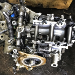 and the extent of the damage.
This reverse order breakdown provides a clear understanding of the windshield repair process, starting from the final steps and working back to the initial preparations.
An exhaust hanger is a crucial component in a vehicle’s exhaust system, designed to support and secure the exhaust pipes and muffler in place. Typically made from rubber, metal, or a combination of both, exhaust hangers are engineered to absorb vibrations and movements generated By the engine and road conditions, thereby mitigating noise and preventing damage to the exhaust system.
The primary function of an exhaust hanger is to maintain the proper alignment of the exhaust system components, ensuring that they do not come into contact with other parts of the vehicle, such as the chassis or suspension. This is vital for preventing wear and tear, which could lead to exhaust leaks or even compromised vehicle performance. The rubber material in many exhaust hangers helps to dampen vibrations, providing a quieter ride and enhancing overall comfort for passengers.
Exhaust hangers come in various shapes and sizes, tailored to fit different vehicle models and exhaust configurations. Over time, they can suffer from wear, cracking, or deterioration due to exposure to heat, moisture, and road grime. Regular inspection of exhaust hangers is essential, as damaged hangers can lead to loose exhaust components, increased noise, and potential damage to the exhaust system, necessitating timely replacement to maintain optimal vehicle performance and safety.
 and ensuring the engine is
 and amount of oil as specified in the owner’s manual.