Download Komatsu 140E-5 Engine SAA6D140E-5 Service Repair Manual –

australian
Performing a transmission fluid flush on a Komatsu 140E-5 with an SAA6D140E-5 engine is a task that should be approached with care, especially for those with limited mechanical experience. click here for more details on the download manual…..


    ADJUSTMENT CROSSHEAD ENGINE KOMATSU SAA6D140E-5 UNIT HM400-3, D155-6, WA500-6 KOMATSU

    HAL HAL PENTING SAAT MENGGANTI POMPA SOLAR PADA UNIT D155A-6, HM400-3R, WA500-6_MUDAH DAN BENAR Salam alat berat Ganti supply pump eh malah muncul problem yang lain, ada error CA778 dan startnya juga lama baru bisa …

Below is a simplified step-by-step guide to help you understand the process. Before you start, make sure you have the necessary tools and materials, and consider consulting the owner’s manual for specific details Related to your machine.

### Tools and Materials Needed:
– New transmission fluid (check the owner’s manual for the correct type and amount)
– Transmission fluid filter (if applicable)
– Fluid evacuation pump or suction pump
– Wrenches and sockets (for removing bolts)
– Clean containers for old fluid
– Funnel for adding new fluid
– Rags or paper towels for cleanup
– Safety gloves and goggles

### Step-by-Step Guide:

1. **Safety First:**
– Ensure the machine is parked on a flat, stable surface.
– Turn off the engine and engage the parking brake.
– Wear safety gloves and goggles to protect yourself.

2. **Locate the Transmission Fluid Dipstick:**
– Open the engine compartment and locate the transmission fluid dipstick. It may be labeled and is usually found near the transmission.

3. **Check the Fluid Level:**
– Pull out the dipstick, wipe it clean with a rag, and reinsert it to check the fluid level. This will give you an idea of how much fluid is currently in the transmission.

4. **Prepare for Fluid Removal:**
– Place a clean container under the transmission to catch the old fluid.
– If your machine has a drain plug, use the appropriate wrench to remove it and allow the old fluid to drain completely. If not, you can use a fluid evacuation pump to remove the fluid through the dipstick tube.

5. **Remove the Old Filter (If Applicable):**
– If your transmission has a filter, locate it and remove it according to the manufacturer’s instructions. This may involve unscrewing it or unclipping it.

6. **Install the New Filter (If Applicable):**
– If you removed a filter, install the new One in its place. Make sure it’s secure and correctly oriented.

7. **Replace the Drain Plug:**
– Once all the old fluid has drained, replace the drain plug and tighten it securely.

8. **Add New Transmission Fluid:**
– Using a funnel, pour the new transmission fluid into the dipstick tube. Refer to your owner’s manual for the correct amount to add.

9. **Check the Fluid Level Again:**
– After adding the new fluid, wait a moment and then remove the dipstick again to check the fluid level. If it’s below the recommended level, add more fluid until it reaches the correct mark.

10. **Start the Engine:**
start the engine and let it run for a few minutes. This will help circulate the new fluid through the system.

11. **Check for Leaks:**
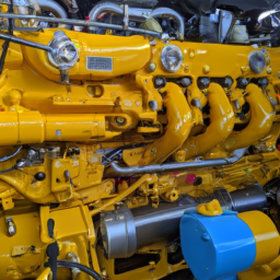
– After running the engine, check around the drain plugdownload Komatsu 140E 5 Engine SAA6D140E 5 workshop manual and filter (if applicable) for any signs of leaking fluid. If you see any leaks, you may need to tighten the plug or filter.
12. **Dispose of Old Fluid Properly:**
– Dispose of the old transmission fluid and any filters according to local regulations. Many auto parts stores or service stations accept used fluid for recycling.

### Final Thoughts:
Completing a transmission fluid flush can help maintain the performance and longevity of your Komatsu 140E-5. Always refer to the owner’s manual for specific instructions Related to your machine. If you are unsure about any part of the process, it might be wise to seek help from a professional mechanic.
A map light, also known as a reading light or interior light, is a small yet essential component found in many vehicles. Positioned typically on the overhead console or near the rearview mirror, the map light serves a practical purpose, providing illumination to help passengers read maps, locate items, or perform other tasks without disturbing the driver.

The design of a map light usually features a focused beam of light that can be adjusted or directed as needed. This adjustability allows occupants to illuminate specific areas, such as a map or a book, while minimizing glare and distraction to the driver. Many modern map lights utilize LED technology, which not only enhances energy efficiency but also prolongs the lifespan of the bulb compared to traditional incandescent options.

In addition to its functional aspects, the map light often contributes to the overall ambiance of the vehicle’s interior. It can be designed to match the vehicle’s aesthetic, offering various color temperatures, brightness levels, and switch types—such as toggle or touch-sensitive controls. Some vehicles even include features like a dimming function, allowing users to adjust the intensity of the light to suit their preferences.

Overall, the map light is a vital component that enhances the convenience and comfort of the driving experience, ensuring that passengers can easily access information or perform tasks without compromising safety.

Download service & repair manual Komatsu 170-3 series –

online
Controlling arm replacement on a Komatsu 170-3 requires careful execution and the right tools. click here for more details on the download manual…..


    Komatsu PC170LC Excavator from Kirby-Smith Machinery is Fast & Comfortable for LASAL, LLC See why this Komatsu PC170LC Excavator from Kirby-Smith Machinery is Fast & Comfortable for LASAL, LLC.

    گیربکس لودرWA470_3 کوماتسو #کوماتسو #گیربکس #لودر #komatsu #WHE…

Below are detailed steps and the tools needed for the process:

### Tools Required:
– **Socket Set**: A comprehensive socket set (including metric sizes) will be needed to remove bolts from the control arm assembly.
– **Wrench Set**: A combination of open-end and box-end wrenches for tightening and loosening nuts and bolts.
– **Torque Wrench**: For ensuring that all bolts are tightened to the manufacturer’s specifications.
– **Pry Bar**: To help in separating parts if they are stuck or difficult to remove.
– **Hammer**: A rubber mallet or dead blow hammer can be used to gently tap components without damaging them.
– **Jack and Jack Stands**: To safely lift and support the vehicle while working underneath it.
– **Pneumatic or Electric Impact Wrench**: For quickly removing stubborn bolts.
– **Suspension Tool Kit**: May include specialized tools for bushings or ball joints if applicable.
– **Safety Gear**: Gloves, safety glasses, and steel-toed boots for personal protection.
– **Grease or Lubricant**: To ease the installation of new components and prevent corrosion.

### Replacement Procedure:
– **Preparation**:
– Park the Komatsu 170-3 on a level surface.
– Engage the parking brake and turn off the ignition.
– Place wheel chocks around the wheels to prevent rolling.

– **Lifting the Vehicle**:
– Use the jack to lift the vehicle at the designated lift points.
– Secure the vehicle with jack stands to ensure it remains stable during the replacement process.

– **Removing the Wheel** (if necessary):
– If the control arm is obstructed by the wheel, remove the wheel by loosening the lug nuts with the socket set and then taking off the wheel.

– **Disconnecting Components**:
identify and remove any components connected to the control arm, such as sway bar links or shock absorbers, using the appropriate tools.
– Using the impact wrench or socket set, remove the bolts securing the control arm to the chassis and the spindle/knuckle.

– **Removing the Old Control Arm**:
– Once all bolts are removed, gently pry the control arm away from its mounting points using a pry bar.
– Inspect the old control arm for wear or damage before discarding it.

– **Preparing for New Control Arm Installation**:
– Clean the mounting surfaces on the chassis and spindle to ensure a good fit for the new control arm.
– Apply grease or lubricant to the bolts and bushings of the new control arm for easier installation.

– **Installing the New Control Arm**:
– Position the new control arm in place and align it with the mounting holes.
– Insert the bolts and hand-tighten them to hold the control arm in position.

– **Tightening Bolts**:
– Using the torque wrench, tighten the bolts to the manufacturer’s specifications, ensuring each bolt is properly secured.
– Reattach any components that were disconnected earlier, such as sway bar links or shock absorbers.

– **Reinstalling the Wheel** (if removed):
– Place the wheel back on the hubdownload Komatsu 170 3 workshop manual and hand-tighten the lug nuts.
– Use the torque wrench to tighten the lug nuts to the manufacturer’s specifications.

– **Lowering the Vehicle**:
– Carefully remove the jack stands and lower the vehicle back to the ground using the jack.
– Re-check the lug nuts and ensure everything is secure.

– **Final Inspection**:
– Before operating the machine, double-check all connections and components.
– Take the vehicle for a short test drive to ensure that everything is functioning properly and that there are no unusual noises or handling issues.

### Disposal:
– Dispose of the old control arm and any other removed components according to local regulations.

By following these steps and using the appropriate tools, you can effectively replace the control arm on a Komatsu 170-3. Always refer to the specific service manual for detailed specifications and torque values related to your model.
The gearbox, also known as a transmission, is a critical component of a vehicle’s drivetrain, responsible for transferring power from the engine to the wheels. It plays a vital role in enabling the vehicle to operate efficiently across a range of speeds and driving conditions. Essentially, the gearbox allows the engine to run at its optimal speed while providing the necessary torque to propel the vehicle forward.

There are two primary types of gearboxes: manual and automatic. A manual gearbox requires the driver to engage the gears by using a clutch pedal and Gear stick, allowing for greater control over the vehicle’s performance. In contrast, an automatic gearbox shifts gears automatically based on the vehicle’s speed and engine load, providing a more convenient driving experience.

Gearboxes consist of various gears, shafts, and other mechanical components that work together to alter the torque and speed delivered to the wheels. The Gear ratios determine how much the engine’s power is multiplied or reduced, enabling the car to accelerate smoothly or climb steep inclines. Advanced gearboxes, such as continuously variable transmissions (CVTs) and dual-clutch transmissions (DCTs), utilize sophisticated systems to provide seamless Gear transitions and improved fuel efficiency.

Overall, the gearbox is essential for optimizing vehicle performance, enhancing drivability, and contributing to fuel economy, making it a cornerstone of automotive engineering.