Download Deutz 2013 2v Engine Spare Parts Catalogue Manual –

get
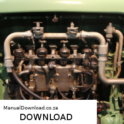
Repairing the suspension crossmember on a Deutz 2V engine can seem daunting, especially if you have little mechanical experience. click here for more details on the download manual…..


    Deutz TCD2012 L04 2V Dyno run of reconditioned Diesel engine Deutz TCD2012 L04 2V Please visit us on wibako.eu.

    Ozka Front Tractor Tires – Review and TEST DRIVE – Deutz Fahr Ӧzka KNK 33 front tractor tires, initial review and test drive. These tires made by @OZKATyre were put on the Deutz Fahr D4506 …

However, I’ll break it down into simple steps. Keep in mind that working on machinery can be dangerous, so always prioritize safety and consult a professional if you’re unsure about any step.

### What is a Suspension Crossmember?

The suspension crossmember is a structural piece that supports the vehicle’s suspension system. It connects the left and right sides of the suspension and helps to stabilize the vehicle.

### Tools and Materials Needed

1. **Basic Tools**:
– Wrenches and sockets (various sizes)
– Screwdrivers
– Pliers
– Hammer
– Jack and jack stands (for lifting the vehicle)
– Safety goggles and gloves

2. **Replacement Parts** (if necessary):
– New crossmember or repair parts
– Bushings or mounts (if needed)

3. **Cleaning Supplies**:
– Degreaser
Rags or paper towels

### Step-by-Step Guide to Repair the Suspension Crossmember

#### Step 1: Safety First
– **Park the Vehicle**: Ensure the vehicle is on a flat surface.
– **Turn Off the Engine**: Make sure the vehicle is turned off and cool.
– **Wear Safety Gear**: Put on your safety goggles and gloves to protect yourself.

#### Step 2: Lift the Vehicle
– **Use the Jack**: Place the jack under the vehicle’s frame and lift it.
– **Secure with Jack Stands**: Once elevated, place jack stands under the vehicle to secure it. Never work under a vehicle supported only by a jack.

#### Step 3: Locate the Crossmember
– **Identify the Part**: The suspension crossmember is usually located near the front of the vehicle, connecting the left and right suspension components.

#### Step 4: Inspect the Crossmember
– **Check for Damage**: Look for any visible cracks, rust, or broken parts. If the crossmember is damaged, it may need to be replaced.

#### Step 5: Remove the Crossmember
– **Loosen Bolts**: Using the appropriate wrench or socket, loosen and remove the bolts that hold the crossmember in place. Keep track of the bolts and nuts as you will need them later.
– **Support the Suspension**: If the crossmember is holding any suspension components, you may need to support them temporarily with a jack or blocks.

#### Step 6: Clean the Area
– **Remove Old Grease and Dirt**: Use a degreaser and Rags to clean the area around the crossmember. This will make it easier to install the new part and check for other potential issues.

#### Step 7: Install the New Crossmember
– **Position the New Part**: Align the new or repaired crossmember where the old one was located.
– **Secure with Bolts**: Hand-tighten the bolts first, then use your wrench to secure them fully. Make sure everything is aligned properly.

#### Step 8: Reassemble Any Removed Components
– **Reconnect Suspension Parts**: If you had to disconnect any parts, reattach them securely.

#### Step 9: Lower the Vehicle
– **Remove Jack Stands**: Carefully take out the jack sdownload Deutz 2v Engine ue workshop manual
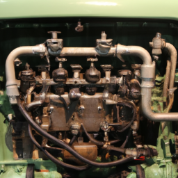
tands and lower the vehicle back to the ground using the jack.

#### Step 10: Test the Repair
– **Check Everything**: Before driving, double-check that all bolts are tight and that nothing is loose.
– **Take a Test Drive**: Go for a short drive to ensure everything feels stable and there are no unusual noises.

### Final Tips
– **Consult the Manual**: If you have access to the service manual for the Deutz engine, refer to it for specific instructions and torque specifications.
– **Ask for Help**: If at any point you feel unsure, don’t hesitate to ask someone with more mechanical experience or consult a professional mechanic.

By following these steps carefully, you can successfully repair the suspension crossmember on a Deutz 2V engine. Remember, safety is paramount, so take your time and don’t rush through any steps!
The hood, also known as the bonnet in some regions, is a vital component of a vehicle that serves several important functions. Located at the front of the car, the hood provides access to the engine compartment, which houses the engine and various other mechanical systems, such as the battery, cooling system, and electrical wiring. Typically made from materials like steel, aluminum, or composite materials, the hood is designed to be both lightweight and durable, helping to protect the engine from external elements while also contributing to the vehicle’s overall aerodynamics.

In terms of design, hoods can vary significantly depending on the make and model of the vehicle. Some hoods feature vents or scoops to improve airflow to the engine or enhance cooling, while others may have a more streamlined appearance for aesthetic purposes. The hood is often equipped with a latch mechanism that secures it in place while driving, ensuring that it remains closed during operation. Safety is also a major consideration; modern hoods are designed to crumple in the event of a collision, reducing the risk of injury to pedestrians.

In addition to its practical uses, the hood plays a significant role in the vehicle’s overall appearance, contributing to its style and character. Custom hoods are popular among car enthusiasts, allowing for personalization and performance enhancements. Whether for maintenance, repairs, or aesthetic appeal, the hood is an essential element of automotive design that combines functionality with style.

Download 2016 BMW 428i xDrive (F36) 4 Series Gran Coupe OEM Download Service & Repair Manual Software –

discount
Repairing the hydraulic clutch on a BMW 428i xDrive F36 Gran Coupe involves several steps. click here for more details on the download manual…..


    BMW 428i gran coupe (F36) cold start

    BMW 435i WITH SPACERS 15m & 20m #bmw #bmwnation #bmw4series #car #bmwmpower #automobile #reac…

Below are the steps presented in reverse order, starting from the completion of the repair and working back to the initial preparations:

### 10. **Reassemble Components:**
– Reinstall any covers or panels that were removed to access the clutch system.
– Ensure all fasteners are tightened to the manufacturer’s specifications.

### 9. **Bleed the clutch System:**
– Use a brake bleeder tool or manual method to bleed the hydraulic system, ensuring all air is removed.
– Check the fluid level and top up as necessary with the recommended brake fluid.

### 8. **Reconnect the clutch Line:**
– If you disconnected the hydraulic line, carefully reconnect it, ensuring a secure fit and no leaks.

### 7. **Replace the clutch Master/Slave Cylinder:**
– If necessary, remove the old master cylinder or slave cylinder and replace it with the new OEM part.
– Secure the new component in place, making sure all connections are tight.

### 6. **Access the Hydraulic Components:**
– Depending on the model year and specific setup, you may need to remove the driver’s side footwell cover to access the clutch master cylinder.

### 5. **Remove the Old Hydraulic Fluid:**
– Use a siphon or turkey baster to remove old hydraulic fluid from the reservoir.
– Dispose of the old fluid in accordance with local regulations.

### 4. **Prepare the Workspace:**
– Gather all necessary tools and materials, including new hydraulic fluid, a wrench set, a brake bleeder tool, and any replacement parts.
– Ensure your vehicle is securely parked and on a flat surface.

### 3. **Disconnect the Battery:**
– Disconnect the negative terminal of the battery to prevent any electrical issues during the repair process.

### 2. **Identify the Problem:**
– Diagnose the issue with the clutch, confirming whether it is a fluid leak, air in the system, or a faulty master/slave cylinder.

### 1. **Gather technical Specifications:**
– Obtain the service manual for the BMW 428i xDrive F36, which includes specifications, torque settings, and diagrams for reference throughout the repair process.

### Additional Tips:
– Always wear safety gear, including gloves and goggles, when working with hydraulic fluids.
– Make sure to work in a well-ventilated area to avoid inhaling fumes from the brake fluid.
– If you’re unsure about any step, consult a professional mechanic or refer to repair forums specific to BMW vehicles.

Following these steps in reverse will help ensure that the hydraulic clutch repair is done systematicallydownload BMW 428i xDrive F36 4 Gran Coupe OEM workshop manual and effectively.
A car Jack is a mechanical device designed to lift a vehicle off the ground, allowing for various maintenance and repair tasks to be performed safely and efficiently. This essential tool is crucial for changing tires, inspecting undercarriage components, or performing brake work, among other automotive tasks.

Car jacks come in several types, with the most common being the hydraulic jack, scissor jack, and floor jack. Hydraulic jacks utilize hydraulic fluid to lift heavy loads and are known for their ease of use and efficiency. They typically feature a piston mechanism that allows for significant lifting power with minimal effort. Scissor jacks are manual devices that operate on a simple lever and screw mechanism, which expands and contracts to lift the car. They are often included with vehicles as part of the tire-changing kit due to their compact size and lightweight design. Floor jacks, on the other hand, are more robust and feature a wide base and large wheels, making them stable and mobile while providing substantial lifting capabilities.

Safety is paramount when using a car jack. It’s critical to ensure that the Jack is placed on a solid, level surface and that the vehicle is in Gear or has its parking brake engaged to prevent it from rolling. Additionally, Jack stands should be used to secure the vehicle once it is elevated, as relying solely on the Jack can be dangerous due to potential mechanical failure. Overall, a car Jack is an indispensable tool for both professional mechanics and DIY enthusiasts, facilitating necessary repairs while ensuring safety and efficiency.

Download Lycoming 0-235-C n 0-290-D aircraft engine Parts manual PC- –

book store
Adjusting the parking brake on a Lycoming O-235-C and O-290-D aircraft engine is a straightforward process, but it requires careful attention to detail to ensure safety and proper functioning. click here for more details on the download manual…..


    世界一周を小型飛行機で軽々と出来るフライトシミュレーター 🛩🌥🌎… ミニチュア版の世界を飛び回り、様々なプロジェクトに荷物を届ける小さなゲーム。 気に入って頂けましたら、是非とも …

Here’s a simple guide to help you understand the steps involved in adjusting the parking brake:

### Tools and materials Needed:
– **Wrench or socket set**: To adjust the brake cable.
– **Screwdriver**: Depending on the type of fasteners used.
– **Safety goggles**: To protect your eyes.
– **Torque wrench**: If specified in the maintenance manual.

### Steps to Adjust the Parking Brake:

1. **Safety First**:
– Ensure the aircraft is parked on a level surface.
– Set chocks behind the wheels to prevent the aircraft from moving.
– Wear safety goggles to protect your eyes from debris.

2. **Locate the Parking Brake Control**:
– The parking brake control is usually found near the pilot’s seat. It can be a lever or a pedal that you push down to engage the brake.
– Familiarize yourself with how it operates before making any adjustments.

3. **Check the Current Brake Operation**:
– Before adjusting, test the parking brake by engaging it and attempting to move the aircraft slightly.
– If the aircraft rolls or the brake feels loose, it may need adjustment.

4. **Find the Brake Cable**:
– Locate the brake cable that connects the parking brake control to the braking mechanism. This cable is typically routed under the floor or behind the panel.

5. **Adjust the Brake Cable**:
– Look for an adjustment nut on the brake cable. This is often found near the parking brake control or at the brake mechanism itself.
– Use a wrench to loosen the locknut (if present) on the adjustment nut.
– Turn the adjustment nut clockwise to tighten the cable (which increases brake tension) or counterclockwise to loosen it (which decreases brake tension).
– Make small adjustments and check the brake operation after each adjustment.

6. **Test the Brake Again**:
– After making adjustments, re-engage the parking brake and test it again by trying to push the aircraft.
– Repeat the adjustment if necessary until the brake holds the aircraft securely when engaged.

7. **Secure All Components**:
– Once satisfied with the brake adjustment, make sure to tighten the locknut to secure the adjustment.
– Double-check that all tools and materials are removed from the area.

8. **Record the Maintenance**:
– It’s a good practice to document any adjustments made to the parking brake in the aircraft’s maintenance log for future reference.

### Final Thoughts:
Adjusting the parking brake is a critical maintenance task that ensures your aircraft is safedownload Lycoming 0 235 C n 0 290 D aircraft engine PC workshop manual and secure when parked. Always consult the aircraft’s maintenance manual for specific instructions and torque specifications, as there may be slight variations between different models. If you are unsure about any step, consider seeking assistance from a qualified mechanic.
The cooling fan is a critical component in an automobile’s cooling system, primarily designed to regulate the engine’s temperature and prevent overheating. Positioned typically in front of the radiator, the cooling fan plays a vital role in maintaining optimal engine performance, especially during low-speed driving or when the vehicle is stationary.

When an internal combustion engine operates, it generates a significant amount of heat. The cooling system, which includes coolant fluid, the radiator, water pump, and thermostat, works to dissipate this heat. However, during certain conditions—like idling in traffic or when driving at slow speeds—the airflow through the radiator can be insufficient. This is where the cooling fan comes into play.

The cooling fan is usually electric or belt-driven. Electric fans are more common in modern vehicles due to their efficiency and the ability to operate independently of the engine speed. When the engine temperature rises above a certain threshold, a temperature sensor triggers the fan to turn on, pulling air through the radiator to enhance heat dissipation. Conversely, when the temperature drops, the fan may switch off to save energy.

In addition to engine cooling, the fan can also assist in cooling the air conditioning condenser, ensuring optimal performance of the vehicle’s climate control system. A malfunctioning cooling fan can lead to engine overheating, reduced efficiency, and potential engine damage, highlighting its importance in vehicle maintenance and performance. Regular checks and prompt repairs of the cooling fan are essential to ensure a vehicle operates smoothly and efficiently.

Download 1982 BMW 732i (E23) 7 Series OEM Download Service & Repair Manual Software –

online
To check the engine light on a BMW 732i E23, you’ll want to follow these steps in reverse order: ### Step 6: **Review Diagnostic Codes** – After the codes have been retrieved, analyze them to understand what issues are present. click here for more details on the download manual…..


    How to: BMW E23 7 Series Power Steering Fluid and Filter Replacement How to replace the power steering fluid and fluid filter on a BMW E23. A similar procedure may also apply to other BMW models of …

    Bmw E23 745i project car! Electrical problem found! This might be really bad? P1 Mail me stuff: WarpDriveM (P.O. Box ) Postfach 1107 67583 Guntersblum Buy merch here: https://warpdrivem.com/shop Use my …

To check the engine light on a BMW 732i E23, you’ll want to follow these steps in reverse order:

### Step 6: **Review diagnostic Codes**
– After the codes have been retrieved, analyze them to understand what issues are present. You can refer to a BMW service manual or an online database to decode the meanings.

### Step 5: **Turn Off the Ignition**
– Once you have finished retrieving and recording the codes, turn off the ignition to complete the diagnostic process.

### Step 4: **Connect the diagnostic Tool**
– Use an OBD-I (On-Board Diagnostics) scanner compatible with BMW vehicles or a specific BMW diagnostic tool. Connect it to the diagnostic port, typically located under the dashboard near the steering column.

### Step 3: **Prepare for Diagnostics**
– Ensure the car is in a safe, stationary position. Turn the ignition key to the “ON” position without starting the engine. This will power up the onboard computer.

### Step 2: **Locate the diagnostic Connector**
– Find the diagnostic connector in the vehicle. For the BMW 732i E23, this is often found beneath the dashboard on the driver’s side.

### Step 1: **Identify the check Engine Light Issue**
– Before initiating diagnostics, observe the check engine light on the dashboard. Note any patterns (steady or blinking)download BMW 732i E23 7 OEM workshop manual and when it activates (e.g., during acceleration, idling, etc.).

By following these steps in reverse, you can effectively check the engine light on a BMW 732i E23. If you encounter specific codes or issues, further troubleshooting or repairs may be necessary.
A drive shaft is a crucial component in a vehicle’s drivetrain system, responsible for transferring torque and rotational energy from the engine to the wheels. Typically made from materials such as steel or aluminum for strength and durability, the drive shaft is designed to withstand the stresses and strains associated with high-speed rotation and varying loads.

The primary function of the drive shaft is to connect the output of the transmission to the differential, which ultimately powers the wheels. In rear-wheel drive vehicles, the drive shaft runs from the transmission at the front of the vehicle to the rear differential. In all-wheel and four-wheel drive systems, multiple drive shafts may be employed to distribute power to both the front and rear wheels, ensuring better traction and handling.

Drive shafts come in various designs, including single-piece and multi-piece configurations, depending on the vehicle’s length and design. They often incorporate universal joints or constant velocity joints, which allow for flexibility and accommodate changes in angle as the suspension moves.

Regular maintenance of the drive shaft is essential, as wear and tear can lead to vibrations, noise, or even failure, which can compromise vehicle safety and performance. Overall, the drive shaft plays a vital role in delivering power efficiently and ensuring a smooth driving experience.

Download KOMATSU PC400-6,PC400LC-6,PC450-6,PC450LC-6 Hydraulic Excavator Service Repair Shop Manual –

australia
Wheel alignment for hydraulic excavators like the KOMATSU PC400-6, PC400LC-6, PC450-6, and PC450LC-6 is not a standard process similar to that of passenger vehicles, as excavators do not have traditional wheels but rather tracks. click here for more details on the download manual…..


    Used 2004 – Komatsu PC450LC-7K for sale | Used tracked excavator | equippo.com | EQUIPPO. The easiest way to buy used equipment For more information on this machine visit …

However, the concept of alignment in the context of an excavator typically involves ensuring that the undercarriage components, such as the track system, are functioning properly and are aligned correctly to ensure optimal operation and prevent excessive wear.

### Overview of Components Involved

1. **Track System**: The tracks provide the mobility of the excavator. They consist of:
– **Track Links**: The individual links that make up the continuous track.
– **Track Shoes**: The part of the track that makes contact with the ground.
– **Idler**: A wheel at the front of the track that helps guide the track.
– **Drive Sprocket**: The gear that drives the track, located at the rear.
– **Rollers**: These support the weight of the excavator and keep the track aligned.

2. **Undercarriage**: This includes all components that support the excavator’s upper structure and provide mobility:
– **Frame**: The main structural component that supports all other parts.
– **Suspension System**: Helps absorb shocks and maintain stability.
– **Track Tensioning System**: Adjusts the tension of the track for optimal operation.

### Steps for Wheel Alignment (Track Alignment) on KOMATSU Excavators

1. **Preparation**:
– **Safety Precautions**: Ensure to wear appropriate personal protective equipment (PPE) and ensure the excavator is on a level surface.
– **Gather tools and Equipment**: You will need:
– A track tension gauge
– Wrenches and sockets
– Alignment tools or a straight edge
– Measuring tape
– Hydraulic jacks (if necessary)

2. **Inspect the Undercarriage**:
– Check for any signs of wear or damage on the track, rollers, idlers, and sprockets.
– Look for any debris that may be lodged in the tracks or undercarriage components.

3. **Check Track Tension**:
– Measure the tension of the track using a track tension gauge. Proper tension is critical for effective track alignment.
adjust the tension using the hydraulic tensioning system if necessary. Typically, the tension should be within the manufacturer’s specifications.

4. **Align the Tracks**:
– Use a straight edge or a measuring tape to measure the distance between the track shoes on both sides of the excavator. This is to ensure that both tracks are at an equal distance from the centerline of the machine.
– If the tracks are misaligned, you may need to adjust the position of the idler or the track adjusters to bring them back into alignment.

5. **Adjust Track Rollers and Idlers**:
– Inspect the track rollers and idlers for proper alignment and wear. They should be aligned parallel to the track.
– If rollers or idlers are misaligned, adjust or replace them as necessary.

6. **Check Sprocket Alignment**:
– Ensure that the drive sprocket is properly aligned with the track. Misalignment can cause excessive wear on the sprocketdownload KOMATSU PC400 6 PC400LC 6 PC450 6 PC450LC 6 Hydraulic Excavator Shop workshop manual and track.
adjust the position of the sprocket if needed.

7. **Final Inspection**:
– After adjustments, perform a visual inspection of the entire undercarriage system to confirm all components are operating correctly.
– Run the excavator at low speed to check for any irregularities in track movement and listen for unusual sounds.

8. **Documentation**:
– Document any findings and adjustments made during the alignment process for future reference.
– Keep a maintenance log for track tension and alignment checks.

### Conclusion

Proper track alignment on a KOMATSU PC400-6, PC400LC-6, PC450-6, and PC450LC-6 excavator is crucial for efficient operation and longevity of the machine. Regular inspections and maintenance of the undercarriage components will help prevent misalignment issues and ensure optimal performance. Always refer to the manufacturer’s service manual for specific torque settings, adjustment procedures, and maintenance schedules.
The throttle cable is a critical component in both traditional and modern internal combustion engine vehicles, playing a pivotal role in controlling the engine’s power output and performance. It connects the accelerator pedal to the throttle body, which regulates the amount of air entering the engine. When a driver presses down on the accelerator pedal, the throttle cable transmits this input to the throttle body, opening the throttle plate and allowing more air to mix with fuel in the combustion chamber. This process increases engine power and speed.

Typically made from a flexible steel wire encased in a protective sheath, the throttle cable is designed to withstand tension and friction as it moves in response to the driver’s input. In older vehicles, this mechanical system provides a direct connection between the pedal and the throttle, offering a tactile response that many drivers find satisfying. However, in modern vehicles, particularly those equipped with electronic throttle control (ETC) systems, the traditional throttle cable has often been replaced by electronic sensors and actuators. In these systems, the accelerator pedal position is detected by sensors, and the throttle is controlled electronically, providing improved fuel efficiency and emissions control.

Regardless of the system used, the throttle cable or its electronic equivalent is essential for the smooth operation of the vehicle, directly affecting acceleration, drivability, and overall performance. Regular maintenance of this component is crucial to ensure proper functioning and avoid issues such as throttle lag or sticking, which can lead to unsafe driving conditions.

Download 2008 MAGNUM All Models Service and Repair Manual –

repair
To perform a Synchro replacement on MAGNUM models, you’ll need to follow a series of steps using specific tools. click here for more details on the download manual…..


    Plus Size Fashion – Maui Beaches Skirt Set #plussizefashion #shorts Welcome to Purpose Plus Size where we talk all about plus size fashion and give you the latest updates on what’s in and trending!

    Metra 70-6504 Amplifier Bypass Harness for Select 2005-2009 Dodge Durango & Dodge Magnum mode… Metra 70-6504 Amplifier Bypass Harness for Select 2005-2009 Dodge Durango & Dodge Magnum models Amazon Product Link: …

Here’s a detailed guide with bullet points:

### Tools Required:

– **Socket Set**:
– Use a complete socket set that includes various sizes. This is essential for loosening and tightening bolts in different areas of the MAGNUM model.

– **Wrench Set**:
– A combination of open-end and box-end wrenches will be necessary to access tight spaces and provide leverage on stubborn bolts.

– **Screwdrivers**:
– A set of flathead and Phillips screwdrivers for removing paneling or any screws securing the Synchro components.

– **Pliers**:
– Needle-nose pliers can be particularly useful for gripping small components or wires that need to be manipulated during the replacement process.

– **Torque Wrench**:
– This tool ensures that all bolts are tightened to the manufacturer’s specifications, crucial for the proper functioning of the Synchro after installation.

– **Replacement Synchro Unit**:
– Ensure you have the correct replacement part that matches the specifications of your MAGNUM model.

– **Sealant or Gasket Maker**:
– Depending on the model and design, you may need a sealant to ensure a proper seal between components.

– **Shop Towels**:
– For cleaning surfaces and wiping off any grease or fluid during the replacement process.

– **Safety Gear**:
– Safety glasses and gloves are crucial to protect yourself from debris and sharp edges during the replacement.

### Procedure:

– **Preparation**:
– Disconnect the battery to ensure safety while working on electrical components.
– Gather all tools and replacement parts before starting to minimize downtime.

– **Accessing the Synchro**:
– Remove any panels or coverings that obstruct access to the Synchro unit. Use screwdrivers and the socket set as necessary.
– Take note of the arrangement of any wiring or components that you may need to disconnect.

– **Disconnecting the Old Synchro**:
– Carefully disconnect any electrical connectors attached to the Synchro.
– Use the appropriate wrench or socket to remove any bolts securing the Synchro in place. Keep all hardware organized for reinstallation.

– **Removing the Old Synchro**:
– Gently pull the old Synchro unit from its housing. Ensure you do not damage surrounding components or wiring.

– **Preparing for Installation**:
– Clean the mounting surface thoroughly to remove any old gasket material or sealant. This will help create a good seal with the new Synchro.
– If required, apply a thin layer of sealant or install a new gasket.

– **Installing the New Synchro**:
– Position the new Synchro in place, ensuring it aligns correctly with the mounting holes.
– Reinstall boltsdownload MAGNUMModels workshop manual and secure them using the torque wrench to the specified torque settings from the manufacturer.

– **Reconnecting Electrical Connections**:
– Reattach any electrical connectors, ensuring they click into place securely.

– **Testing**:
– Before closing everything up, reconnect the battery and perform a test to ensure the new Synchro is functioning correctly.
– Check for any unusual noises or warning lights on the dashboard during this test.

– **Final Assembly**:
– Once confirmed that everything is functioning properly, reattach any panels or coverings that were removed.
– Ensure all tools are accounted for and the work area is clean.

– **Documentation**:
– Consider documenting the replacement process for future reference or maintenance records.

By following these steps and using the described tools, you can successfully replace the Synchro on MAGNUM models. Always refer to the specific service manual for your model for any unique instructions or specifications.
The pressure plate is a critical component in a vehicle’s clutch system, playing a vital role in the engagement and disengagement of the engine’s power to the transmission. Located within the clutch assembly, the pressure plate works in conjunction with the clutch disc and the flywheel. Its primary function is to apply pressure to the clutch disc, which is situated between the pressure plate and the flywheel. This pressure is essential for transmitting the engine’s torque to the transmission when the clutch is engaged.

When the driver presses the clutch pedal, a release mechanism (such as a hydraulic or cable system) disengages the pressure plate from the clutch disc. This action allows the clutch disc to rotate freely, enabling smooth gear shifts without grinding. The pressure plate is typically made from durable materials such as steel or aluminum to withstand the high temperatures and forces encountered during operation.

There are various types of pressure plates, including diaphragm and coil spring designs, each offering different characteristics that affect the clutch’s feel and performance. A well-functioning pressure plate is crucial for efficient power transfer, providing smooth engagement and disengagement while minimizing wear on the clutch components. regular maintenance and inspection of the pressure plate are important, as wear or damage can lead to clutch slippage, difficulty in shifting gears, or complete failure of the clutch system.

Download 2021 RAM 1500 Pickup 3.6L V6 24v VVT ETorque UPG I Service & Repair Manual –

service manual
Certainly! click here for more details on the download manual…..


    Ram 1500 E-TORQUE HYBRID System *Heavy Mechanic Review* | Does It ACTUALLY Work?? I Review the RAM 1500 5.7L hemi/3.6L pentastar ETorque Hybrid Engines and explain the pros and cons of this electric hybrid …

    RAM 1500 V6 3.6L Pentastar (E-Torque) **Heavy Mechanic Review** | Is It a Good Engine ?? Is the RAM 1500 V6 3.6L Pentastar a good engine? I review this V6 RAM engine as a Heavy Duty Mechanic and give you my …

below is a reverse order explanation of how to replace the wheel bearing on a RAM 1500 Pickup with a 3.6L V6 engine. Please remember that this is a general guide and may not cover all specifics for your model year. Always consult your vehicle’s service manual for detailed instructions.

### Reverse Order steps for Wheel Bearing Replacement

1. **Reinstall the Wheel and Tire**:
– Place the wheel onto the hub.
– Hand-tighten the lug nuts.
– Lower the vehicle from the jack stands.
– Use a torque wrench to tighten the lug nuts to the manufacturer’s specified torque.

2. **Reinstall the brake Caliper**:
– Align the brake caliper over the brake rotor.
– Install the caliper bolts and tighten to the manufacturer’s specifications.
– Reconnect the brake line if it was disconnected.

3. **Reattach the Hub Assembly**:
– If applicable, position the new hub assembly onto the steering knuckle.
– Insert the bolts and tighten them to the specified torque.

4. **Install New Wheel Bearing**:
– Press the new wheel bearing into the hub assembly using a bearing press or appropriate tool.
– Ensure it is seated correctly.

5. **Remove Old Wheel Bearing**:
– Using a bearing puller, remove the old wheel bearing from the hub assembly.
– Clean the hub area thoroughly to prepare for the new bearing.

6. **Disconnect the brake Components**:
– Remove the brake caliper by unbolting it from the bracket.
– Hang it with a wire to avoid putting stress on the brake line.
– Remove the brake rotor if necessary.

7. **Remove the Wheel**:
– Loosen the lug nuts using a lug wrench.
– Lift the vehicle using a jack and secure it with jack stands.
– Remove the lug nuts completely and take off the wheel.

8. **Prepare the Vehicle**:
– Park the vehicle on a level surfacedownload RAM 1500 Pickup 3.6L V6 24v VVT ETorque UPG I workshop manual and set the parking brake.
– Gather all necessary tools and parts (new wheel bearing, hub assembly, brake cleaner, torque wrench, etc.).

### Important Notes
– Always wear safety gear, including Gloves and safety glasses.
– Ensure the vehicle is secure on jack stands before starting work.
– Follow all safety and torque specifications as per the vehicle’s service manual.

This reverse guide should help you understand the steps involved in replacing the wheel bearing on your RAM 1500. If you’re not confident performing this task, consider consulting a professional mechanic.
A seatbelt retractor is a critical safety component of automotive seatbelt systems, designed to manage the seatbelt’s length and ensure that it functions effectively during both normal use and in the event of a collision. The primary function of a seatbelt retractor is to allow for the smooth extension and retraction of the seatbelt webbing. This mechanism is typically housed within a compact unit mounted to the vehicle’s seat or frame.

When a passenger sits in the vehicle and fastens their seatbelt, the retractor allows the webbing to extend to accommodate the individual’s size and seating position. The retractor is equipped with a spool, which is connected to a spring mechanism. When the seatbelt is pulled, the spool unwinds, allowing the belt to extend. However, if the force on the belt increases suddenly—such as during a crash—the retractor engages a locking mechanism. This can be achieved through various methods, including a pendulum or inertia reel, which locks the belt in place, preventing additional movement and helping to secure the occupant in their seat.

The design and functionality of seatbelt retractors have evolved significantly over the years, with modern systems incorporating features such as pretensioners, which tighten the belt upon collision, further enhancing occupant safety. Overall, the seatbelt retractor plays a vital role in the overall effectiveness of seatbelt systems, contributing to the reduction of injuries and fatalities in automotive accidents.

Download 2003-2017 Ford C-Max Service & Repair Manual Software –

diy
Replacing the shock absorbers on a Ford C-Max involves several steps and requires specific tools and safety precautions. click here for more details on the download manual…..


    SYMPTOMS OF BAD CV AXLE SHAFT demonstrated FORD C-MAX SYMPTOMS OF BAD CV AXLE SHAFT demonstrated FORD C-MAX If you have Ford C-MAX and you want to know the symptoms …

    KYB FORD C Max – Rear Fitting video showing the correct fitment of shock absorbers to the rear of: C-MAX II 04.2010 – 06.2019 FOCUS III 07.2010 …

Here’s a detailed guide with bullet points outlining the process and tools needed:

### Tools Required:
– **Jack and Jack Stands**: Essential for lifting the vehicle safely and securely.
– **Lug Wrench**: For removing wheel nuts.
– **Socket Set**: Includes various sizes, typically 10mm to 21mm sockets.
– **Ratchet and Extensions**: For easy access to bolts in tight spaces.
– **Torque Wrench**: To ensure bolts are tightened to manufacturer specifications.
– **Pry Bar**: Useful for separating components if they are stuck.
– **Spring Compressor**: If you’re replacing struts, this tool compresses the coil spring safely.
– **Impact Wrench (optional)**: Speeds up the removal of bolts but requires caution.
– **Pliers**: For removing clips or stubborn components.
– **Rust Penetrant (e.g., WD-40)**: Helps loosen rusted bolts.
– **Gloves and Safety Glasses**: Personal protective equipment to ensure safety during the process.
– **Shop Manual or Repair Guide**: For specific torque settings and diagrams if needed.

### Replacement Process:
– **Preparation**:
– Park the vehicle on a flat, stable surface.
– Engage the parking brake and place wheel chocks behind the rear wheels for added safety.

– **Loosen Wheel Nuts**:
– Use the lug wrench to slightly loosen the nuts on the wheel where you’ll be replacing the shock absorber.

– **Lift the Vehicle**:
– Position the jack under the designated lift point and raise the vehicle.
– Secure the vehicle with jack stands to ensure stability.

– **Remove the Wheel**:
– Fully remove the loosened wheel nuts and take off the wheel to expose the suspension components.

– **Locate the Shock Absorber**:
– Identify the shock absorber attached to the suspension system. The C-Max typically has a damper on each side of the rear axle.

– **Remove the Shock Absorber**:
– At the top mount: Use a socket and ratchet to remove the bolt securing the top of the shock absorber.
– At the bottom mount: Remove the bolt at the bottom of the shock absorber using the appropriate socket.
– If necessary, use a pry bar to detach the shock from the mounting points if it’s stubborn.

– **Install the New Shock Absorber**:
– Position the new shock absorber in place, aligning it with the mounting points.
– Insert and hand-tighten the bolts at both the top and bottom to hold it in place.

– **Torque the Bolts**:
– Use a torque wrench to tighten the bolts to the manufacturer’s specified torque settings. Refer to a repair manual for exact figures.

– **Reattach the Wheel**:
– Replace the wheel and hand-tighten the lug nuts.
– Lower the vehicle off the jack stands using the jack.

– **Final Tightening**:
– Once the vehicle is on the ground, use the lug wrench to fully tighten the wheel nuts in a crisscross pattern for even distribution.

– **Repeat for Other Side**:
– If replacing all shock absorbers, repeat the above steps for the opposite side.

– **Test Drive**:
– After replacing the shocks, take the car for a short drive to ensure everything is functioning properly. Listen for any unusual noises that may indicate improper installation.

### Safety Tips:
– Always wear glovesdownload Ford C Max workshop manual and safety glasses to protect against debris and sharp edges.
– Ensure the vehicle is stable and secure on jack stands before working underneath it.
– Be cautious when using the spring compressor, as compressed springs can be dangerous if released improperly.

By following these steps carefully and using the right tools, you can successfully replace the shock absorbers on a Ford C-Max.
The drive belt, often referred to as the serpentine belt in modern vehicles, is a crucial component of an internal combustion engine’s accessory drive system. Its primary function is to transfer power from the engine’s crankshaft to various peripheral devices, such as the alternator, power steering pump, water pump, air conditioning compressor, and sometimes the cooling fan. This belt is typically made from a durable rubber composite, which is designed to withstand the rigors of heat, friction, and environmental exposure.

The design of the drive belt has evolved over the years. Older vehicles often employed multiple belts for different accessories, but modern vehicles predominantly use a single serpentine belt that winds around multiple pulleys, maximizing efficiency and reducing space under the hood. This configuration simplifies maintenance, as it is easier to replace a single belt than multiple ones.

Regular inspection of the drive belt is essential, as wear and tear can lead to cracking, fraying, or stretching. A failing drive belt can result in a loss of power to vital components, which may lead to issues such as overheating, loss of steering assistance, and electrical failures. Most manufacturers recommend checking the drive belt at regular intervals and replacing it according to the vehicle’s maintenance schedule to ensure optimal performance and avoid potential breakdowns on the road.

Download DODGE RAM Truck 3.7L 4.7L 5.7L 5.9L Diesel 6.7L Service Repair Manual 2008 –

book shop
Replacing a control arm on a Dodge Ram truck can seem daunting if you have little mechanical experience, but with some patience and the right guidance, you can do it. click here for more details on the download manual…..


    Engine Cylinder Numbering Explained This covers inline and v8 style engines(Ford and everyone else)

    Top 5 Problems Dodge Ram Truck 3rd Generation 2002-08 Shop for New Auto Parts at 1AAuto.com http://1aau.to/c/240/L/evap-emission-control-system-parts This top problems features the …

Below is a simplified step-by-step guide to help you understand the process. Remember to take safety precautions, and if you’re unsure at any step, consider asking a more experienced friend or a professional for help.

### Tools and Materials Needed:
– Safety glasses and gloves
– Jack and jack stands
– Lug wrench
– Socket set (including metric sizes)
– Wrench set
– Hammer
– Prying tool or screwdriver
– Torque wrench
– Replacement control arm
– New bolts (if necessary)

### Steps to Replace a Control Arm:

1. **Preparation:**
– Park the truck on a flat surface and engage the parking brake.
– Wear safety glasses and gloves to protect yourself.

2. **Lift the Truck:**
– Use the lug wrench to loosen the lug nuts on the wheel where you’ll be replacing the control arm (do not remove them completely yet).
– Use the jack to lift the truck and secure it with jack stands. Never work under a vehicle supported only by a jack.

3. **Remove the Wheel:**
– Finish removing the lug nuts and take off the wheel to expose the suspension components.

4. **Locate the Control Arm:**
– The control arm is the component that connects the wheel hub assembly to the vehicle’s frame. It looks like a “V” shape and has bushings at both ends.

5. **Remove the Old Control Arm:**
– Locate the bolts securing the control arm to the frame and the ball joint that connects it to the steering knuckle (the part that holds the wheel).
– Use the appropriate socket and wrench to remove these bolts. You may need to use a hammer to free up any rusted or stuck bolts.
– If the ball joint is difficult to remove, you can use a prying tool or a ball joint separator tool.

6. **Install the New Control Arm:**
– Position the new control arm in place. Align it with the mounting holes in the frame and the ball joint.
– Insert the bolts and hand-tighten them to hold the control arm in place.

7. **Tighten the Bolts:**
– Using the torque wrench, tighten the bolts to the manufacturer’s specifications (check your vehicle’s service manual for specific torque settings). This ensures that everything is secure and safe.

8. **Reattach the Wheel:**
– Place the wheel back on the hub and hand-tighten the lug nuts.
– Lower the truck back to the ground using the jack and then fully tighten the lug nuts in a crisscross pattern to ensure even pressure.

9. **Check Your Work:**
– Inspect the control armdownload DODGE RAM Truck 3.7L 4.7L 5.7L 5.9L 6.7L workshop manual and ensure everything is securely fastened.
– Make sure there are no leftover parts and that everything is in order.

10. **Test Drive:**
– Take the truck for a short test drive in a safe area to ensure everything feels right. Listen for any unusual noises or handling issues.

### Final Notes:
– Replacing a control arm is a crucial job that affects your vehicle’s handling and suspension. If you’re ever in doubt, it’s a good idea to consult with a professional mechanic.
– Always refer to your vehicle’s service manual for specific instructions and torque specifications tailored to your model and year.

Safety is the most important factor, so take your time and ensure everything is done correctly. Good luck!
A battery cable is a crucial component in a vehicle’s electrical system, serving as the conduit for electrical energy between the battery and other components of the vehicle. Typically made from copper or aluminum, battery cables are designed to efficiently conduct electrical current while minimizing resistance and heat generation. They are often coated with a durable insulation material, usually PVC or rubber, to protect against environmental factors such as moisture, heat, and mechanical abrasion.

Battery cables come in two main types: positive and negative. The positive battery cable connects the positive terminal of the battery to the vehicle’s starter and other electrical systems, while the negative cable connects the negative terminal to the vehicle’s chassis or engine block, creating a ground connection. This grounding is essential for the proper operation of the vehicle’s electrical systems, as it helps to complete the electrical circuit.

The gauge of the battery cable is also significant, as it determines the amount of current the cable can safely carry. Thicker cables (lower gauge numbers) can handle higher currents, making them essential for high-performance vehicles or those with significant electrical demands. Over time, battery cables can corrode, fray, or become damaged, leading to poor electrical connections, which can result in starting issues or electrical failures. Regular inspection and maintenance of battery cables are vital for ensuring reliable vehicle performance and safety.

Download 2002 SUBARU IMPREZA CAR Service & Repair Manual – ! –

australian
Replacing the water pump on a Subaru Impreza can be a bit challenging, especially if you have little mechanical experience, but I will guide you through the process step-by-step. click here for more details on the download manual…..


    Top 5 Problems Subaru Impreza Hatchback 5th Generation 2017-21 For More Info visit us at: http://1aau.to/h/cog/ Do you own a 2017 to 2021 Subaru Impreza? The 5th generation of this model is not …

    #1 Upgrade for STI Transmissions If you own an STI with a 6-speed transmission, you may have experienced gear lockouts and grinds due to worn-out OEM …

Before we begin, please make sure you have the necessary tools and materials:

### tools and Materials Needed:
1. **Tools:**
– Socket set (including extensions)
– Wrenches
– Screwdrivers (flathead and Phillips)
– Pliers
– Torque wrench
– Gasket scraper or razor blade (if needed)
– Funnel
– Drain pan
– Rags or paper towels

2. **Materials:**
– New water pump
– New gasket or gasket sealant (if needed)
– New coolant
– New timing belt (optional but recommended if applicable)

### Steps to Replace the water Pump:

#### 1. **Preparation:**
– **Safety First:** Make sure the engine is cool and the car is parked on a flat surface. Engage the parking brake.
– **Disconnect the Battery:** To avoid any electrical issues, disconnect the negative terminal of the battery.

#### 2. **Drain the Coolant:**
– **Locate the Drain Plug:** Under the radiator, there should be a drain plug. Place the drain pan underneath it.
– **Open the Drain Plug:** Carefully open the drain plug to let the coolant flow out. Once it’s drained, close the plug.

#### 3. **Remove Components:**
– **Remove the Timing Belt Cover (if applicable):** Locate the cover that protects the timing belt. Remove the screws or bolts holding it in place.
– **Remove the Timing Belt (if applicable):** If your water pump is driven by the timing belt, you will need to remove it. Take note of how the belt is positioned. You might need to loosen the tensioner to do this.
– **Remove any Obstructions:** Depending on your engine layout, you may need to remove other components like the alternator, power steering pump, or other belts to access the water pump.

#### 4. **Remove the water Pump:**
– **Locate the water Pump:** It’s usually located on the front of the engine.
– **Unbolt the water Pump:** Remove the bolts securing the water pump using the socket set. Keep track of where each bolt goes.
– **Take off the Old water Pump:** Once the bolts are removed, gently pull the water pump off. If it’s stuck, you can gently tap it with a rubber mallet.

#### 5. **Install the New water Pump:**
– **Clean the Surface:** Use a gasket scraper or razor blade to clean any old gasket material off the engine block.
– **Install the New Pump:** Place the new water pump onto the engine, making sure it aligns correctly with the bolt holes.
– **Bolt it Down:** Reinstall the boltsdownload SUBARU IMPREZA CAR workshop manual and tighten them to the manufacturer’s specifications (you can find this in a repair manual). Be careful not to overtighten.

#### 6. **Reassemble:**
– **Reinstall Timing Belt (if applicable):** If you removed the timing belt, install it back in the correct orientation. Ensure proper tension as per specifications.
– **Reinstall Components:** Put back any components you removed (like the timing belt cover, alternator, etc.).

#### 7. **Refill Coolant:**
– **Add New Coolant:** Open the radiator cap and use a funnel to pour in new coolant. Fill it to the recommended level.
– **Bleed the System:** If necessary, run the engine with the radiator cap off to let air bubbles escape. Keep an eye on the coolant level and add more if needed.

#### 8. **Reconnect the Battery:**
– Reconnect the negative terminal of the battery.

#### 9. **Test:**
– Start the engine and let it run for a few minutes. Check for leaks around the water pump and ensure the engine is not overheating.

### Additional Tips:
– If you’re unsure about any step, consult your vehicle’s service manual or look for online tutorials specific to your Subaru Impreza model.
– It’s a good idea to replace the timing belt if it’s due, as it’s often necessary to remove it to access the water pump.
– Always dispose of old coolant and parts properly.

### Conclusion:
Replacing the water pump requires patience and attention to detail. Make sure to work carefully, and don’t hesitate to ask for help if needed. Good luck with your water pump replacement!
A shift cable is a critical component in the transmission system of a vehicle, responsible for facilitating the operation of the gear shift mechanism. Typically made of a flexible metal or plastic-coated wire, the shift cable connects the gear shifter inside the cabin to the transmission itself, which is usually located in the engine compartment or under the vehicle. When the driver moves the gear shifter, the shift cable transmits that motion to the transmission, allowing for the selection of different gears, whether in automatic or manual vehicles.

The shift cable operates by translating the linear motion of the gear lever into the angular motion required for the transmission to engage or disengage the selected gear. In automatic transmissions, the cable may also be linked to the vehicle’s computer systems, providing feedback on the gear selection and enabling smooth transitions between gears.

Over time, shift cables can experience wear and tear, which can lead to issues such as difficulty in shifting gears, unintended gear changes, or complete inability to change gears. Regular inspections can help identify problems early, and replacement of a faulty shift cable is often necessary to ensure smooth gear operation. Overall, the shift cable plays a vital role in the drivability and performance of a vehicle, making it an essential component for safe and efficient driving.