Download 2006 Mercury Mariner Owners Manual –

get
Replacing a transmission torque sensor on a Mercury Mariner involves a series of steps that require careful attention to detail. click here for more details on the download manual…..


    Upgrading to LED in The 08 Mercury Mariner Dana's Garage Thank you for supporting My channels by Liking , Subscribing, Sharing and Checking out these Descriptions and LINKs below.

    Mariner Mercury 2.5hp 2 stroke carburetor setting's #outboard #mercury #mariner #tohatsu Mariner Mercury 2.5hp 2 stroke carburetor setting’s #outboards #mercury #mariner #tohatsu.

The torque sensor is responsible for measuring the torque being applied by the engine to the transmission, which is critical for the vehicle’s performance and transmission control. Below is a detailed guide on how to replace the transmission torque sensor, including descriptions of all necessary components and tools.

### Tools and Materials Needed

1. **Basic Hand Tools**:
– Ratchet and socket set (including metric and standard sizes)
– Wrenches (open-end and box)
– Screwdrivers (Philips and flathead)
– Pliers
– Torque wrench

2. **Safety Equipment**:
– Safety glasses
– Gloves

3. **Replacement Parts**:
– New transmission torque sensor
– New O-rings or seals (if applicable)
– Transmission fluid (if any is lost during the process)

4. **Diagnostic Tools** (optional but recommended):
– OBD-II scanner (to clear codes after installation)

### Steps for Replacement

#### 1. Preparation

– **Disconnect the Battery**:
– Open the hood and locate the battery. Use a wrench to disconnect the negative terminal first to prevent any electrical shorts.

– **Lift the Vehicle**:
– Use a jack to lift the front of the vehicle and secure it on jack stands. This provides sufficient room to access the transmission.

#### 2. Locate the Torque Sensor

– **Access the Transmission**:
– Depending on the vehicle’s model year and engine type, the torque sensor is typically located on or near the transmission bell housing or along the transmission case.
– Refer to the vehicle’s service manual for the exact location.

#### 3. Remove the old Torque Sensor

– **Identify the Wiring Harness**:
– Follow the wiring harness connected to the torque sensor. Carefully unplug the electrical connector by pressing the release tab and pulling it apart.

– **Remove Fasteners**:
– Use the appropriate socket or wrench to remove the bolts or screws securing the torque sensor to the transmission. Keep these fasteners as you will need them for the new sensor.

– **Extract the Sensor**:
– Gently pull the torque sensor out of its housing. If it is stuck, you may need to wiggle it slightly or use a soft tool to pry it out, being careful not to damage surrounding components.

#### 4. Install the New Torque Sensor

– **Prepare the New Sensor**:
– Compare the new sensor with the old One to ensure they are identical. Check that any O-rings or seals are in place.

– **Insert the New Sensor**:
– Slide the new torque sensor into its designated location on the transmission. Ensure it is seated properly.

– **Secure the Sensor**:
– Reinstall the bolts or screws that secure the sensor. tighten them to the manufacturer’s specifications using a torque wrench.

#### 5. Reconnect the Wiring

– **Plug in the Electrical Connector**:
– Carefully reconnect the wiring harness to the new torque sensor. Ensure the connector clicks into place securely.

#### 6. Reassembledownload Mercury Mariner workshop manual and Test

– **Lower the Vehicle**:
– Remove the jack stands and lower the vehicle back to the ground.

– **Reconnect the Battery**:
– Reconnect the negative terminal of the battery.

– **Check Transmission Fluid**:
– If any fluid was lost during the process, check the transmission fluid level and add fluid as necessary.

#### 7. Clear Codes (if applicable)

– **Use an OBD-II Scanner**:
– If the vehicle’s check engine light was on due to a faulty torque sensor, use an OBD-II scanner to clear any diagnostic trouble codes (DTCs) related to the torque sensor.

#### 8. Test Drive

– **Perform a Test Drive**:
– Start the engine and take the vehicle for a test drive. Pay attention to the shifting behavior and ensure that there are no warning lights on the dashboard.

### Final Notes

– Always refer to the vehicle’s service manual for specific torque specifications and recommendations.
– If unsure about any step, consider consulting a professional mechanic.
– Proper handling and disposal of any old parts and fluids are essential for environmental safety.

By following these detailed steps, you can successfully replace the transmission torque sensor on a Mercury Mariner.
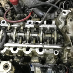
The crankshaft is a vital component of an internal combustion engine, serving as the primary link between the engine’s pistons and the vehicle’s drivetrain. Its primary function is to convert the linear motion of the pistons, which are driven by the combustion of fuel and air, into rotational motion. This transformation is essential for powering the vehicle, as the rotational motion can ultimately be transmitted to the wheels.

Typically made from high-strength steel or iron, the crankshaft is designed to withstand significant stresses and strains. It features several key elements, including crankpins, main journals, and counterweights. The crankpins connect to the connecting rods, which in turn are linked to the engine’s pistons. As the pistons move up and down in their cylinders during the combustion cycle, the crankpins rotate around the crankshaft’s axis, generating rotational movement.

Counterweights are strategically placed on the crankshaft to balance the engine and minimize vibrations, enhancing performance and longevity. The design and precision of the crankshaft are crucial; any imbalance can lead to excessive wear and tear on engine components, decreased efficiency, and potential engine failure.

Moreover, the crankshaft is often equipped with a harmonic balancer, which reduces vibrations caused by the engine’s operation. In summary, the crankshaft is indispensable for converting energy produced during combustion into mechanical energy that propels the vehicle, playing a crucial role in engine performance and efficiency.

Download Kobelco SK170-9 Service Manual –

service manual
Repairing the transmission on a Kobelco SK170-9 excavator is a complex task that usually requires mechanical knowledge and experience. click here for more details on the download manual…..


    Kobelco SK170 Excavating Land [3-1-2021] Here’s a kitchen window shot of a Kobelco SK170 excavating land of a former single family home that was demolished a few days …

    2012 Kobelco SK170-9 Excavator 2012 Kobelco SK170-9 Excavator See more Kobelco SK170 listings here: …

However, I can provide a simplified overview of the process. Please remember that If you’re not familiar with heavy machinery, it’s best to consult a professional mechanic or technician for this kind of work. Here’s a Basic guide:

### Tools and Materials Needed:
Basic hand tools (wrenches, sockets, screwdrivers)
– Torque wrench
– Oil catch pan
replacement parts (gaskets, seals, filters, fluid)
safety gear (gloves, goggles)

### Steps for Transmission Repair:

1. **Safety First**:
– **Turn Off the Machine**: Make sure the excavator is turned off and the keys are removed.
– **Safety Gear**: Put on your gloves and goggles to protect yourself.

2. **Prepare the Work Area**:
– Ensure the area is clean and free of clutter.
– Make sure you have enough space to work around the excavator.

3. **Remove the Transmission Access Panels**:
– Locate the access panels on the transmission housing.
– Use your tools to remove any bolts or screws holding the panels in place.

4. **Drain the Transmission Fluid**:
– Place an oil catch pan under the transmission to collect the fluid.
remove the drain plug and allow the fluid to completely drain out.

5. **Inspect the Transmission**:
– Look for any visible signs of damage or wear, such as broken gears, frayed belts, or leaks.
– Check the fluid for metal shavings or debris, which can indicate internal damage.

6. **Disassemble the Transmission (if necessary)**:
If you find significant damage, you may need to disassemble the transmission.
– Carefully remove bolts and components, keeping track of where each part goes.
– Take photos If necessary to remember the assembly order.

7. **Replace Worn or Damaged Parts**:
– Install new gaskets, seals, and filters as needed.
– Replace any damaged gears or components. Ensure that you use parts that are compatible with the Kobelco SK170-9.

8. **Reassemble the Transmission**:
– Carefully put all parts back together in the reverse order of disassembly.
– Ensure all bolts are tightened to the manufacturer’s specified torque settings.

9. **Refill Transmission Fluid**:
– Replace the drain plug.
– Refill the transmission with the appropriate typedownload Kobelco SK170 9 workshop manual and amount of fluid as specified in the owner’s manual.

10. **Test the Transmission**:
– Replace the access panels and secure them.
– Start the excavator and allow it to run for a few minutes.
– Test the transmission by moving the machine forward and backward to ensure it operates smoothly.

11. **Check for Leaks**:
– After testing, inspect the transmission area for any signs of leakage.

12. **Dispose of Old Fluid Properly**:
– Make sure to dispose of the old transmission fluid in accordance with local environmental regulations.

### Final Note:
This guide is a simplified overview, and actual transmission repair can be much more complicated than described. It’s crucial to refer to the specific service manual for the Kobelco SK170-9 for detailed instructions and specifications. If you’re unsure at any point, don’t hesitate to seek help from a qualified mechanic.
The coolant reservoir, often referred to as the expansion tank or coolant overflow tank, is a critical component of a vehicle’s cooling system. Its primary function is to store excess coolant that may expand during the engine’s operation, particularly when it heats up. As the engine runs, the coolant circulates through the engine block and radiator, absorbing heat. When the coolant temperature rises, it expands and creates pressure within the cooling system. The coolant reservoir provides a safe space for this excess coolant to go, preventing damage to the system.

Typically made of plastic, the coolant reservoir is usually located near the radiator and is marked with minimum and maximum level indicators, allowing drivers to easily check the coolant level. It is connected to the cooling system via hoses, facilitating the flow of coolant back and forth. In addition to storing excess coolant, the reservoir also allows for the return of coolant as the engine cools down and the fluid contracts.

Regular maintenance of the coolant reservoir is important, as a leak or crack can lead to coolant loss, resulting in overheating and potential engine damage. Moreover, keeping the coolant at the proper level is essential for optimal engine performance, as it ensures efficient heat dissipation. Thus, the coolant reservoir plays a vital role in maintaining engine temperature and overall vehicle reliability.

Download Komatsu PC1250-7 shop manual –

diy
Replacing the anti-roll bar on a Komatsu PC1250-7 involves several steps, and it’s essential to follow a reverse order for clarity. click here for more details on the download manual…..


    The Komatsu PC1250 is a BEAST! 👀💪 #Shorts #Komatsu #heavyequipment #construction #mining The Komatsu PC1250 is a GIGANTIC, HUGE, BIG, AND ALL OF THE ABOVE BEAST OF A MACHINE! Learn more about how …

    komatsu PC 210-6 remove engine starter

Here’s a guide to help you understand the process in reverse:

### 5. Reinstall the Components
– **Reattach the Anti-Roll Bar**: position the new or repaired anti-roll bar in place, ensuring it aligns correctly with the mounting points.
– **Secure the Bolts**: Tighten all bolts and nuts to the manufacturer’s specified torque settings using a torque wrench. Ensure everything is secure.

### 4. Lower the Machine
– **Remove Safety Supports**: If you have used jack stands or supports, carefully remove them.
– **Lower the Equipment**: Lower the machine from the jacks or lift, making sure everything is stable.

### 3. Install New Components
– **Attach New Bushings**: If you have new bushings for the bar, install them onto the anti-roll bar in their respective positions.
– **Position the Anti-Roll Bar**: Carefully lift the anti-roll bar into position, ensuring it is correctly aligned with the suspension components.

### 2. Remove Old Anti-Roll Bar
– **Disconnect the Links**: Unbolt and remove any links connected to the anti-roll bar (if applicable).
– **Unfasten the Bar**: Remove the bolts securing the anti-roll bar to the chassis and suspension.

### 1. Prepare the Work Area
– **Safety Precautions**: Ensure the machine is on a flat, stable surface. Engage the parking brake and place wheel chocks.
– **Gather Tools and Parts**: Collect necessary tools (wrenches, sockets, torque wrench) and the replacement anti-roll bar and bushings.

### Additional Considerations:
– Always refer to the specific service manual for the Komatsu PC1250-7 for detailed instructions and torque specifications.
– Check for any other components that may need inspection or maintenance while you have access to the suspension system.
– Dispose of any old parts responsibly and follow safety protocols throughout the replacement process.

This reverse order provides a clear overview of the steps involved in replacing the anti-roll bar on a Komatsu PC1250-7. Always prioritize safetydownload Komatsu PC1250 7 shop workshop manual and consult the manufacturer’s guidelines for any specific details related to your equipment.
The mass airflow sensor (MAF sensor) is a critical component in an automotive engine management system, playing a pivotal role in optimizing engine performance and efficiency. Its primary function is to measure the amount of air entering the engine, which is essential for determining the correct air-fuel mixture needed for combustion. This measurement is crucial because an optimal air-fuel ratio ensures efficient engine operation, leading to better fuel economy, reduced emissions, and improved overall performance.

Typically located between the air filter and the intake manifold, the MAF sensor uses various technologies to gauge airflow, including hot wire and vane-type sensors. In a hot wire MAF sensor, a thin wire is heated electrically, and as air flows over it, the cooling effect of the incoming air changes the wire’s temperature. The sensor then calculates the amount of air entering the engine based on the amount of current needed to maintain the wire’s temperature. on the other hand, vane-type sensors utilize a mechanical flap that opens with incoming air, translating the position of the flap into an airflow reading.

The data collected by the MAF sensor is sent to the engine control unit (ECU), which adjusts fuel injection accordingly. A malfunctioning MAF sensor can lead to various issues, including poor fuel economy, rough idling, and increased emissions. Therefore, maintaining the MAF sensor is essential for ensuring reliable vehicle operation and compliance with environmental regulations.

Download 2013 BMW 320d EfficientDynamics (F31) 3 Series Touring OEM Download Service & Repair Manual Software –

owners manual
Replacing the muffler on a BMW 320d EfficientDynamics F31 3 Touring can seem daunting if you have little mechanical experience, but with the right guidance, you can do it yourself! click here for more details on the download manual…..


    Unlock this Hidden Feature in Your BMW

    BEST BMW F30 Upgrades! Are you the lucky owner of a BMW 3 Series F30? It’s one of the most popular BMWs out there, but also one full of upgrade …

Here’s a simple step-by-step guide.

### Tools and Materials Needed:
1. **New Muffler**: Make sure it’s the correct OEM part for your BMW 320d.
2. **Socket Set**: Typically, you will need 10mm and 13mm sockets.
3. **Wrench Set**: To hold bolts and nuts in place.
4. **Pliers**: For any clamps or hangers.
5. **Jack and Jack Stands**: To lift the car safely.
6. **Safety Glasses**: To protect your eyes.
7. **Gloves**: To keep your hands clean.
8. **Rust Penetrant**: (like WD-40) to help loosen any rusty bolts.

### Step-by-Step Instructions:

#### 1. Safety First
– **Park your car on a flat surface** and engage the parking brake.
– **Put on your safety glasses and gloves**.

#### 2. Lift the Car
– Use a **jack to lift the rear of the car**. Make sure to place jack stands under the car for safety. Never work under a car supported only by a jack.

#### 3. Locate the Muffler
– The muffler is located at the rear of the car, under the back bumper. It is the large cylindrical component in the exhaust system.

#### 4. Inspect the Existing Muffler
– Before removing it, check how it is connected. most mufflers are held in place with **clamps and hangers**.

#### 5. Remove the Old Muffler
– **Spray rust penetrant** on the bolts and clamps to make them easier to remove.
– Use the **socket set and wrench** to remove the bolts that hold the muffler in place.
– If there are clamps, use pliers to loosen them.
– Carefully slide the muffler off its hangers. You may need to gently twist or pull it out from the exhaust pipe.

#### 6. Prepare the New Muffler
– Before installing the new muffler, compare it with the old one to ensure they are the same size and shape.

#### 7. Install the New Muffler
– Slide the new muffler onto the exhaust pipe and align it with the hangers.
– Secure it using the bolts and clamps you removed earlier. Make sure everything is tight, but be careful not to overtighten, which could damage the parts.

#### 8. Check Everything
– Double-check all connections to ensure everything is secure and properly aligned.
– Make sure the hangers are supporting the mufflerdownload BMW 320d EfficientDynamics F31 3 Touring OEM workshop manual and that there are no gaps.

#### 9. Lower the Car
– Carefully remove the jack stands and lower the car back to the ground.

#### 10. Test the Installation
– Start the engine and listen for any unusual noises. The exhaust should be quiet, and there shouldn’t be any leaks.

### final Thoughts
If you notice any issues, double-check your work. If you’re unsure about any step, it’s always a good idea to consult a professional mechanic or refer to the vehicle’s manual for more specifics. Good luck with your muffler replacement!
The brake proportioning valve is a critical component in a vehicle’s braking system, designed to optimize the braking force distributed between the front and rear wheels. In most vehicles, the braking system uses hydraulic pressure to engage the brakes, and the proportioning valve plays a vital role in ensuring that this pressure is balanced appropriately.

When a driver applies the brakes, the weight of the vehicle shifts forward, resulting in increased traction at the front wheels and reduced traction at the rear wheels. If the braking force is not proportioned correctly, this can lead to rear wheel lockup during hard braking, which may cause the vehicle to skid or lose control. The brake proportioning valve mitigates this risk by regulating the pressure that is sent to the rear brakes, ensuring they engage with less force than the front brakes.

Typically, the valve is calibrated to allow more braking pressure to the front wheels, which are responsible for most of the deceleration. It operates based on the vehicle’s dynamics, adjusting the brake force as needed, particularly during sudden stops or when the vehicle is loaded with passengers or cargo. Some modern vehicles incorporate electronic brake proportioning systems that utilize sensors to dynamically adjust brake force, further enhancing safety and control. Overall, the brake proportioning valve is essential for maintaining vehicle stability and ensuring effective braking performance.

Download 2022 RAM 1500 Pickup 5.7L V8 Hemi MDS VVT ETorque Service & Repair Manual –

repair manual
Replacing the shift solenoid on a 2022 RAM 1500 Pickup with a 5.7L V8 Hemi engine can be a bit complex, but I’ll break it down into simple steps. click here for more details on the download manual…..


    2022 Ram 1500 Denver, Littleton, Aurora, Parker, Colorado Springs, CO R7861 Billet Silver Metallic Clearcoat New 2022 Ram 1500 available in Denver Colorado at Brandon Dodge. Servicing the Littleton …

    What is eTorque? New Ram 1500 information A question I get a lot from new and existing Ram customers is in regards to the new eTorque technology. In this video I explain …

Before starting, make sure you have the necessary tools and parts, and always prioritize safety. Here’s a step-by-step guide:

### Tools and materials Needed:
1. **New Shift Solenoid**: Make sure it’s compatible with your RAM 1500.
2. **Basic Hand Tools**: Socket set, wrenches, and screwdrivers.
3. **Torque Wrench**: For tightening bolts to the correct specification.
4. **Jack and Jack Stands**: To lift the vehicle safely if needed.
5. **Drain Pan**: To catch any fluid that may spill.
6. **Gloves and Safety Glasses**: To protect yourself.

### Steps for Replacement:

#### Step 1: Safety First
– **Park the Vehicle**: Ensure the vehicle is on a flat surface.
– **Disconnect the Battery**: Remove the negative battery cable to prevent any electrical issues while you work.

#### Step 2: Access the Transmission
– **Lift the Vehicle**: If necessary, use a jack to lift the front of the truck and place it securely on jack stands.
– **Locate the Transmission**: The shift solenoid is inside the transmission. Depending on the model, you may need to remove some components or covers to access it.

#### Step 3: Drain Transmission Fluid
– **Position Drain Pan**: Place the drain pan under the transmission pan.
– **Remove the Transmission Pan**: Use a socket to remove the bolts holding the pan in place. Carefully lower the pan to allow the fluid to drain completely.

#### Step 4: Remove the Shift Solenoid
– **Locate the Shift Solenoid**: Inside the transmission, find the shift solenoid. It may be attached with a connector and a few bolts.
– **Disconnect the Electrical Connector**: Gently pull the connector off the solenoid.
– **Remove the Bolts**: Use the socket to unscrew the bolts holding the solenoid in place. Be careful not to drop any bolts into the transmission.

#### Step 5: Install the New Shift Solenoid
– **Position the New Solenoid**: Place the new shift solenoid in the same position as the old one.
– **Secure it with Bolts**: Hand-tighten the bolts first, then use a torque wrench to tighten them to the manufacturer’s specifications.
– **Reconnect the Electrical Connector**: Ensure it clicks into place securely.

#### Step 6: Reassemble the Transmission
– **Reattach the Transmission Pan**: Clean the surface of the pan and install a new gasket if necessary. Secure it with the bolts and tighten them evenly.
– **Add Transmission Fluid**: Pour the appropriate type of transmission fluid through the dipstick tube or fill port. check your owner’s manual for specifications.

#### Step 7: final Checks
– **Reconnect the Battery**: Put the negative battery cable back on.
– **Start the Engine**: Let it run for a few minutesdownload 2022 RAM 1500 Pickup 5.7L V8 Hemi MDS VVT ETorque workshop manual and check for any leaks.
– **Test Drive**: Take the vehicle for a short drive to ensure the solenoid is functioning properly.

### Conclusion
Replacing the shift solenoid can be a challenging task, but with patience and careful attention to detail, it can be done successfully. If you’re unsure at any point, it’s always a good idea to consult a professional mechanic. Always refer to your vehicle’s service manual for specific instructions and torque specifications.
A leaf spring is a type of suspension component commonly used in vehicles, particularly in trucks, vans, and some passenger cars. It consists of several layers, or “leaves,” of flat, elongated spring steel that are stacked together in a manner that creates a curved shape. This design allows the leaf spring to flex under load, absorbing shocks and impacts from the road while supporting the vehicle’s weight. The primary purpose of leaf springs is to provide a balance between ride comfort and load-carrying capacity, making them ideal for heavy-duty applications.

Leaf springs are typically mounted on the vehicle’s axle and connect to the frame. When a load is applied, the leaves compress and flex, distributing the weight evenly across the suspension system. This helps maintain proper vehicle height and stability, enhancing handling and safety. Leaf springs also have a natural damping effect, which reduces the impact of bumps and rough terrain on the vehicle’s occupants.

One of the advantages of leaf springs is their simplicity and robustness, which makes them relatively easy to manufacture and maintain. They are also cost-effective compared to more complex suspension systems. However, they can be less effective in providing a smooth ride compared to modern coil spring systems, especially in passenger vehicles. despite this, leaf springs remain a popular choice for applications requiring high load capacity and durability, such as in commercial vehicles and off-road applications.

Download 2006 Nissan Maxima Service & Repair Manual Software –

service manual
Repairing a dual-clutch transmission (DCT) on a Nissan Maxima is a complex process that requires a good understanding of automotive mechanics and access to specialized tools. click here for more details on the download manual…..


    Radiator replacement 2014 Maxima

    2022 Nissan Maxima Muffler Delete

Below is a detailed guide outlining the tools needed and the general steps involved in the repair process. This is a high-level overview and may not cover every specific detail for your model year, so please consult a service manual for exact specifications.

### tools Needed:

– **Socket Set**:
– A complete set of metric sockets (including deep sockets) to remove various bolts and fasteners.
– Ratchet and extension bars for reaching tight spaces.

– **Torque Wrench**:
– A click-type or beam-type torque wrench to ensure that bolts are tightened to the manufacturer’s specified torque settings.

– **Screwdriver Set**:
– Flat-head and Phillips screwdrivers for removing covers and small components.

– **Pliers**:
– Needle-nose and regular pliers for gripping and pulling small parts.

– **Transmission Fluid Pump**:
– To refill the transmission fluid accurately after repairs.

– **Transmission Jack**:
– A specialized jack to safely support and lower the transmission during removal and installation.

– **Oil Catch Pan**:
– To catch any fluid that may leak out during the repair process.

– **O-ring and Gasket Kit**:
– Replacement seals and gaskets to prevent leaks after reassembly.

– **Diagnostic Scanner**:
– An OBD-II scanner to check for error codes and perform system diagnostics.

– **Shop Manual/Service Manual**:
– A detailed guide specific to the Nissan Maxima that includes repair procedures, specifications, and torque settings.

– **Work Light**:
– To illuminate the work area for better visibility.

### General Steps for Dual-Clutch Transmission Repair:

– **Preparation**:
– Gather all tools and materials needed before starting the repair.
– Ensure you have a clean workspace and proper safety equipment (gloves, goggles).

– **Disconnect Battery**:
– Disconnect the negative terminal of the battery to prevent electrical shorts during the repair.

– **Lift the Vehicle**:
– Use a hydraulic jack to lift the front of the vehicle and secure it on jack stands for safety.

– **Drain Transmission Fluid**:
– Place an oil catch pan under the transmission and remove the drain plug to allow the fluid to drain completely.

– **Remove Underbody Covers**:
– Use the socket set and screwdrivers to remove any underbody panels or covers that obstruct access to the transmission.

– **Disconnect Transmission Components**:
– Detach the drive shafts, electrical connectors, and any other components that connect to the transmission.
– Label wires and components for easy reinstallation.

– **Remove the Transmission**:
– Use the transmission jack to support the transmission, then remove the mounting bolts.
– Carefully lower the transmission from the vehicle.

– **Disassemble the Transmission**:
– Following the service manual, carefully disassemble the transmission. Take note of the order of parts for reassembly.
– Inspect components such as clutches, gears,download Nissan Maxima workshop manual and actuators for wear or damage.

– **Replace Worn Components**:
– Replace any damaged or worn components using the O-ring and gasket kit for seals.
– Ensure that all new parts meet OEM specifications.

– **Reassemble the Transmission**:
– Carefully reassemble the transmission in the reverse order of disassembly, ensuring all components are correctly positioned and torqued to specification.

– **Reinstall the Transmission**:
– Use the transmission jack to lift the transmission back into place. Reattach mounting bolts and ensure everything is secure.

– **Reconnect Components**:
– Reattach all drive shafts, electrical connectors, and any other components that were removed.

– **Refill Transmission Fluid**:
– Use the transmission fluid pump to refill the transmission with the recommended fluid type, ensuring to check the level per the manufacturer’s specifications.

– **Reconnect Battery**:
– Reattach the negative terminal of the battery.

– **Test Drive**:
– Start the vehicle and check for any leaks or abnormal noises. Perform a test drive to ensure the transmission operates smoothly.

– **Run Diagnostics**:
– Use the diagnostic scanner to check for any error codes and confirm that the transmission control module (TCM) is functioning properly.

### Final Notes:

– Always consult the specific service manual for your Nissan Maxima model year for detailed instructions and specifications.
– If you are not experienced in transmission repair, consider seeking professional assistance to avoid potential damage to the vehicle.
A tire pressure sensor is a crucial component of a vehicle’s tire pressure monitoring system (TPMS), designed to monitor and report the air pressure within the tires. These sensors play a vital role in ensuring vehicle safety and performance by helping to maintain optimal tire pressure, which is essential for fuel efficiency, handling, and overall driving safety.

There are two primary types of tire pressure sensors: direct and indirect. Direct tire pressure sensors are located inside the tire, typically attached to the valve stem. They use a small battery-powered transmitter to send real-time data about tire pressure to the vehicle’s onboard computer system. Indirect tire pressure sensors, on the other hand, do not measure pressure directly. Instead, they rely on the vehicle’s anti-lock braking system (ABS) to monitor wheel rotation speed. If a tire is under-inflated, it has a smaller diameter and rotates faster than properly inflated tires, triggering a warning light on the dashboard.

The functionality of tire pressure sensors is critical, as under-inflated tires can lead to increased tire wear, decreased fuel efficiency, and a higher risk of tire blowouts. Many modern vehicles come equipped with TPMS as a standard feature, with warnings activated when tire pressure drops below a specified threshold. Regularly checking tire pressure and ensuring that sensors are functioning correctly is essential for safe vehicle operation and optimal driving performance.

Download 2012 Volkswagen Golf Mk6 R 5 Doors Download Service & Repair Manual –

bookshop
Installing a suspension lift kit on a Volkswagen Golf Mk6 R (5-door) involves several steps and requires a good understanding of automotive mechanics. click here for more details on the download manual…..


    VW Golf R MK6 2.0 TSI DSG 270 PS Top Speed Drive German Autobahn No Speed Limit POV 2010 VW Golf 6 R 2.0 TSI DSG 4Motion 199 kW/270 PS 350 Nm 1984 ccm 1521 kg 200.000 km No Speedlimit Topspeed Drive …

    VW Golf R MK6 with 2-STEP ANTI-LAG!! – INSANE Flames & Bangs @ Wörthersee *MUST SEE* Facebook: http://www.fb.com/NM2255 – Instagram http://www.instagram.com/nicknm2255/ ○ Now this is the loudest 2 Step I have …

Below is a detailed guide, along with descriptions of each component involved in the installation process.

### Components of a Suspension Lift Kit

1. **Lift Spacers**: These are used to increase the height of the vehicle. They are typically made from polyurethane or aluminum and are placed above the strut assembly.

2. **Extended Struts/Shocks**: If the lift is significant, you may need longer struts or shocks to maintain proper suspension travel and geometry.

3. **Control Arm Drop Brackets**: These are used to lower the control arms to maintain proper angles for suspension components.

4. **Alignment Kit**: Camber and toe bolts may be needed to adjust the alignment after the lift is installed.

5. **Hardware (Bolts, Nuts, Washers)**: New hardware may be included in the kit to ensure a secure fit.

6. **Instructions Manual**: most kits come with installation instructions specific to the vehicle.

### Tools Required

– Socket set (metric)
– Wrenches (metric)
– Torque wrench
– Jack and jack stands
– Spring compressor (if needed)
– Screwdrivers
– Pliers
– Hammer
– Safety glasses
– Gloves

### Preparation Steps

1. **Safety First**: Ensure you are working in a well-ventilated area. Wear safety glasses and gloves.

2. **Gather Tools and Components**: Have all tools and lift kit components ready for the installation.

3. **Lift the Vehicle**: Use a jack to lift the front of the car and secure it on jack stands. Ensure the vehicle is stable before proceeding.

4. **Remove the Wheels**: Use a socket wrench to remove the lug nuts and take off the wheels, exposing the suspension components.

### Installation Steps

#### Front Suspension

1. **Remove the Strut**:
– Locate the top strut nuts under the hood (usually three per strut).
– Remove these nuts with a socket wrench.
– Underneath the vehicle, remove the bolts that secure the strut to the steering knuckle.
– Carefully pull the strut out of the wheel well.

2. **Install Lift Spacers**:
– If using lift spacers, place them on top of the strut assembly.
– Align the spacer holes with the strut holes.

3. **Reinstall the Strut**:
– Insert the strut back into the wheel well, securing it to the steering knuckle first.
– Tighten the bolts to the manufacturer’s specified torque.

4. **Secure the Top of the Strut**:
go back to the engine bay and secure the top of the strut with the nuts you previously removed.
– Tighten them to the specified torque.

5. **Repeat for the other Side**: Follow the same procedure for the other front strut.

#### Rear Suspension

1. **Remove Rear Shocks**:
– Access the rear shocks by removing any necessary panels or covers.
– Remove the top nut securing the shock and then the bottom bolt.
– Pull out the shock absorber.

2. **Install Lift Kit Components**:
– Depending on the kit, you may need to install lift spacers or new extended shocks.
– If using spacers, install them above the shock mount.

3. **Reinstall Rear Shocks**:
– Insert the new or modified shock into place.
– Secure the bottom bolt and the top nut. Ensure everything is tightened to the manufacturer’s specifications.

4. **Repeat for the other Side**: perform the same steps for the other rear shock absorber.

### Final Steps

1. **Reinstall the Wheels**: Place the wheels back onto the hubdownload Volkswagen Golf Mk6 R 5 Doors workshop manual and hand-tighten the lug nuts. Then, lower the vehicle from the jack stands and fully tighten the lug nuts in a star pattern.

2. **Check Alignment**: After installation, it’s crucial to have a professional alignment performed to ensure proper driving characteristics and tire wear.

3. **Test Drive**: Carefully take the vehicle for a test drive to ensure everything is functioning correctly and to check for any unusual noises or handling issues.

### Post-Installation

– After the installation, periodically check the bolts and hardware for any loosening.
– Monitor the vehicle’s handling and ride quality; adjustments may be necessary based on personal preference or driving conditions.

### Conclusion

Installing a suspension lift kit on a Volkswagen Golf Mk6 R can enhance its off-road capabilities and aesthetic appeal. However, it requires careful attention to detail and adherence to safety practices. Always refer to the specific instructions that come with your lift kit, as variations in design may require different steps or components.
The alternator bracket is a crucial component in the Automotive electrical system, serving as a supportive structure for the alternator, which generates electrical power for the vehicle. This bracket is typically made from durable materials such as steel or aluminum, designed to withstand the vibrations and stresses experienced during vehicle operation. Its primary function is to securely mount the alternator to the engine block, ensuring proper alignment and stability while allowing the alternator to operate efficiently.

The alternator itself is responsible for converting mechanical energy from the engine into electrical energy, which powers the vehicle’s electrical systems and charges the battery. The alternator bracket plays a vital role in this process by maintaining the alternator in the correct position for optimal belt alignment. This is essential because the alternator is driven by a serpentine belt connected to the engine’s crankshaft. If the alternator is misaligned due to a faulty or damaged bracket, it can lead to belt slippage, excessive wear, or even belt failure, which would compromise the electrical system’s functionality.

In addition to providing support, the alternator bracket often features multiple mounting points for securing the alternator and may include provisions for additional components, such as tensioners or idler pulleys. Over time, the bracket can be subject to wear and tear, leading to the need for replacement to maintain the overall efficiency and performance of the vehicle’s electrical system. Proper installation and maintenance of the alternator bracket are essential for ensuring the longevity and reliability of the alternator and the vehicle’s electrical components.

Download Komatsu 140E-5 Engine SAA6D140E-5 Service Repair Manual –

australian
Performing a transmission fluid flush on a Komatsu 140E-5 with an SAA6D140E-5 engine is a task that should be approached with care, especially for those with limited mechanical experience. click here for more details on the download manual…..


    ADJUSTMENT CROSSHEAD ENGINE KOMATSU SAA6D140E-5 UNIT HM400-3, D155-6, WA500-6 KOMATSU

    HAL HAL PENTING SAAT MENGGANTI POMPA SOLAR PADA UNIT D155A-6, HM400-3R, WA500-6_MUDAH DAN BENAR Salam alat berat Ganti supply pump eh malah muncul problem yang lain, ada error CA778 dan startnya juga lama baru bisa …

Below is a simplified step-by-step guide to help you understand the process. Before you start, make sure you have the necessary tools and materials, and consider consulting the owner’s manual for specific details Related to your machine.

### Tools and Materials Needed:
– New transmission fluid (check the owner’s manual for the correct type and amount)
– Transmission fluid filter (if applicable)
– Fluid evacuation pump or suction pump
– Wrenches and sockets (for removing bolts)
– Clean containers for old fluid
– Funnel for adding new fluid
– Rags or paper towels for cleanup
– Safety gloves and goggles

### Step-by-Step Guide:

1. **Safety First:**
– Ensure the machine is parked on a flat, stable surface.
– Turn off the engine and engage the parking brake.
– Wear safety gloves and goggles to protect yourself.

2. **Locate the Transmission Fluid Dipstick:**
– Open the engine compartment and locate the transmission fluid dipstick. It may be labeled and is usually found near the transmission.

3. **Check the Fluid Level:**
– Pull out the dipstick, wipe it clean with a rag, and reinsert it to check the fluid level. This will give you an idea of how much fluid is currently in the transmission.

4. **Prepare for Fluid Removal:**
– Place a clean container under the transmission to catch the old fluid.
– If your machine has a drain plug, use the appropriate wrench to remove it and allow the old fluid to drain completely. If not, you can use a fluid evacuation pump to remove the fluid through the dipstick tube.

5. **Remove the Old Filter (If Applicable):**
– If your transmission has a filter, locate it and remove it according to the manufacturer’s instructions. This may involve unscrewing it or unclipping it.

6. **Install the New Filter (If Applicable):**
– If you removed a filter, install the new One in its place. Make sure it’s secure and correctly oriented.

7. **Replace the Drain Plug:**
– Once all the old fluid has drained, replace the drain plug and tighten it securely.

8. **Add New Transmission Fluid:**
– Using a funnel, pour the new transmission fluid into the dipstick tube. Refer to your owner’s manual for the correct amount to add.

9. **Check the Fluid Level Again:**
– After adding the new fluid, wait a moment and then remove the dipstick again to check the fluid level. If it’s below the recommended level, add more fluid until it reaches the correct mark.

10. **Start the Engine:**
start the engine and let it run for a few minutes. This will help circulate the new fluid through the system.

11. **Check for Leaks:**
– After running the engine, check around the drain plugdownload Komatsu 140E 5 Engine SAA6D140E 5 workshop manual and filter (if applicable) for any signs of leaking fluid. If you see any leaks, you may need to tighten the plug or filter.

12. **Dispose of Old Fluid Properly:**
– Dispose of the old transmission fluid and any filters according to local regulations. Many auto parts stores or service stations accept used fluid for recycling.

### Final Thoughts:
Completing a transmission fluid flush can help maintain the performance and longevity of your Komatsu 140E-5. Always refer to the owner’s manual for specific instructions Related to your machine. If you are unsure about any part of the process, it might be wise to seek help from a professional mechanic.
A map light, also known as a reading light or interior light, is a small yet essential component found in many vehicles. Positioned typically on the overhead console or near the rearview mirror, the map light serves a practical purpose, providing illumination to help passengers read maps, locate items, or perform other tasks without disturbing the driver.

The design of a map light usually features a focused beam of light that can be adjusted or directed as needed. This adjustability allows occupants to illuminate specific areas, such as a map or a book, while minimizing glare and distraction to the driver. Many modern map lights utilize LED technology, which not only enhances energy efficiency but also prolongs the lifespan of the bulb compared to traditional incandescent options.

In addition to its functional aspects, the map light often contributes to the overall ambiance of the vehicle’s interior. It can be designed to match the vehicle’s aesthetic, offering various color temperatures, brightness levels, and switch types—such as toggle or touch-sensitive controls. Some vehicles even include features like a dimming function, allowing users to adjust the intensity of the light to suit their preferences.

Overall, the map light is a vital component that enhances the convenience and comfort of the driving experience, ensuring that passengers can easily access information or perform tasks without compromising safety.

Download Mitsubishi D04FD-TAA Diesel Engine* Factory Service / Repair/ Workshop Manual ! –

book store
Replacing the water pump on a Mitsubishi D04FD TAA engine involves several steps and requires a basic understanding of engine components, as well as the appropriate tools. click here for more details on the download manual…..


      Mitsubishi engine timing gear mark orders 153624 fg oder crank cap tourqe 300lbs connecting road cap tourqe 80lbs head bolt tourqe 120lbs valve clearance 40 inlet 60 …

    Below, I’ll provide a detailed guide to help you through the replacement process.

    ### Tools and Materials Needed:

    1. **Tools:**
    – Socket set (including extensions and universal joints)
    – Wrench set
    – Torque wrench
    – Screwdrivers (flat and Phillips)
    – Pliers
    gasket scraper (or razor blade)
    – Engine hoist (if necessary for access)
    – Timing belt tools (if applicable)
    – Drain pan
    – Shop towels or rags

    2. **Materials:**
    – New water pump (specific to Mitsubishi D04FD TAA)
    – New gasket or sealant (if applicable)
    – New coolant
    – New timing belt (if the water pump is driven by the timing belt and it’s due for replacement)

    ### Step-by-Step Replacement Procedure:

    #### 1. Preparation:

    – **Safety First**: Ensure the engine is cool. Disconnect the negative terminal of the battery to prevent any electrical issues during the repair.

    – **Drain Coolant**: Place a drain pan under the radiator and open the drain valve to drain the coolant. You can also remove the lower radiator hose for complete drainage.

    #### 2. Remove Components for Access:

    – **Access the Water Pump**: Depending on the engine layout, you may need to remove various components to access the water pump, such as:
    – **Timing Belt Cover**: If the water pump is behind the timing belt, remove the timing belt cover by unscrewing the bolts.
    – **Timing Belt**: If the water pump is driven by the timing belt, you will need to remove the belt. Use a tensioner tool to relieve tension before removing the belt.
    – **Accessory Belts**: Remove any Accessory belts that may obstruct access to the water pump. Loosen the tensioners and remove the belts from the pulleys.

    – **Other Components**: You might need to remove additional components such as the alternator, power steering pump, or engine mounts depending on the accessibility of the water pump.

    #### 3. Remove the Old Water Pump:

    – **Unscrew the Water Pump**: Locate the bolts securing the water pump to the engine block. Use the appropriate socket to remove these bolts. Keep track of the bolts as you will need them for the new pump.

    – **Remove the Water Pump**: Once the bolts are removed, gently pull the water pump away from the engine block. If it is stuck, carefully tap it with a rubber mallet to loosen it.

    – **Clean the Mounting Surface**: Use a gasket scraper or razor blade to remove any old gasket material from the engine block. Ensure that the surface is clean and free of debris to ensure a proper seal with the new pump.

    #### 4. Install the New Water Pump:

    – **Prepare the New Pump**: If your new water pump requires a gasket, apply gasket sealant if specified in the manufacturer’s instructions. Align the gasket with the pump if applicable.

    – **Position the New Pump**: Place the new water pump onto the engine block, ensuring it is aligned with the bolt holes.

    – **Install Bolts**: Hand-tighten the bolts into the water pump to secure it in place. Then, use a torque wrench to tighten the bolts to the manufacturer’s specified torque settings (consult the service manual for the exact torque values).

    #### 5. Reassemble Components:

    – **Reinstall the Timing Belt (if removed)**: If you removed the timing belt, ensure the timing marks are aligneddownload Mitsubishi D04FD TAA Engine workshop manual and then reinstall the belt. Adjust the tension according to the manufacturer’s specifications.

    – **Reattach Accessory Belts**: Reinstall any Accessory belts you removed. Ensure they are properly tensioned.

    – **Reinstall Any other Components**: Reattach any components you removed for access, such as the timing belt cover or engine mounts. Make sure all bolts are tightened to the specified torque.

    #### 6. Refill Coolant:

    – **Close Drain Valve**: If you drained the radiator, close the drain valve and reconnect the lower radiator hose.

    – **Refill Coolant**: Using a funnel, refill the cooling system with the appropriate type of coolant specified for your engine. Start with the radiator and then fill the overflow reservoir.

    #### 7. Test the System:

    – **Reconnect the Battery**: Reconnect the negative terminal of the battery.

    – **Start the Engine**: Start the engine and let it run for a few minutes. Check for leaks around the water pump area and ensure the engine reaches operating temperature.

    – **Check Coolant Levels**: After the engine has cooled down, check the coolant level again and top off if necessary.

    #### 8. Final Checks:

    – **Inspect for Leaks**: After running the engine, inspect the water pump and surrounding areas for any signs of leaking coolant.

    – **Dispose of Old Coolant**: Make sure to dispose of the old coolant and any waste materials according to local environmental regulations.

    ### Conclusion:

    Replacing the water pump on a Mitsubishi D04FD TAA engine is a straightforward process if you follow these steps carefully. Always refer to your vehicle’s service manual for specific details and torque specifications. If you are not confident in performing this replacement, consider seeking help from a professional mechanic.
    The turbo drain pipe is a crucial component in a turbocharged engine system. Its primary function is to facilitate the efficient removal of oil that has been used to lubricate the turbocharger. In a turbocharged engine, the turbocharger operates at high speeds and generates significant heat, necessitating proper lubrication to prevent wear and overheating. The turbo drain pipe is designed to collect the oil that drains from the turbocharger’s bearing housing after it has performed its lubricating function.

    Typically made from materials that can withstand high temperatures and resist oil degradation, the turbo drain pipe connects the turbocharger to the engine’s oil return system, allowing the oil to flow back into the engine’s sump. This return is essential for maintaining the correct oil levels, preventing oil starvation, and ensuring that the turbocharger operates smoothly and efficiently.

    Moreover, the design of the turbo drain pipe is engineered to minimize restrictions and ensure proper drainage, which is vital for the turbocharger’s performance. A well-functioning turbo drain pipe prevents oil from pooling in the turbocharger, which could lead to increased pressure and potential oil leaks or turbo failure. In summary, the turbo drain pipe plays a vital role in the longevity and efficiency of a turbocharged engine by ensuring optimal lubrication and preventing oil-related issues.

    Download OPEL OMEGA B 1994-2003 Workshop Service Repair Manual –

    workshop manual
    Replacing the heater core in an Opel Omega B can be a challenging task, especially for someone with little mechanical experience. click here for more details on the download manual…..


      Omega B 2.2 Tuning by RVD Garage

      Opel Omega B – Check For These Issues Before Buying What problems await you after buying a used Opel Omega B 1994 2003. The Opel Omega B is a large family car that was in …

    However, with patience and a clear understanding of the steps involved, you can accomplish this task. Here’s a simple guide to help you through the process.

    ### Tools and Materials Needed:
    – Screwdrivers (flathead and Phillips)
    – Socket set and ratchet
    – Pliers
    – A container to catch coolant
    – New heater core
    – New coolant
    – Towels or rags
    – Safety glasses and gloves

    ### Step-by-Step Guide:

    #### 1. **Preparation:**
    – **Safety First:** Ensure the car is parked on a level surface, turn off the ignition, and engage the parking brake. Wear safety glasses and gloves.
    – **Disconnect the Battery:** To avoid any electrical issues, disconnect the negative terminal of the battery.

    #### 2. **Drain the Coolant:**
    – Locate the radiator drain valve (usually at the bottom of the radiator) and place a container underneath it.
    – Open the valve to let the coolant drain out. Be careful as the coolant can be hot. Close the valve when finished.

    #### 3. **Remove Dashboard Components:**
    – **Remove the Center Console:** You may need to take out screws and clips holding the center console in place. Carefully lift it out and set it aside.
    – **Take Out the Dashboard:** This step can be complex. Look for screws and bolts securing the dashboard, especially around the instrument panel and glove compartment. Disconnect any electrical connectors as you go. Note where everything goes for reassembly.

    #### 4. **Access the Heater Core:**
    – Once the dashboard is removed, you should see the heater box, which contains the heater core.
    – Locate the heater core hoses at the firewall (the wall between the engine bay and the cabin).

    #### 5. **Disconnect the Heater Core Hoses:**
    – Use pliers to loosen the clamps on the heater core hoses and carefully slide them off. Be prepared for any remaining coolant to spill out, so have your container ready.

    #### 6. **Remove the Heater Core:**
    – Find any screws or bolts securing the heater core to the heater box. Remove them carefully.
    – Gently pull the heater core out of the heater box. Be cautious not to damage any surrounding components.

    #### 7. **Install the New Heater Core:**
    – Take your new heater core and insert it into the heater box, ensuring it fits snugly.
    – Reattach any screws or bolts you removed earlier to secure it in place.

    #### 8. **Reconnect the Heater Core Hoses:**
    – Slide the hoses back onto the heater core and tighten the clamps securely.

    #### 9. **Reassemble the Dashboard:**
    – Carefully put the dashboard back in place, reconnecting all electrical connectors and securing it with screws and bolts.
    – Reinstall the center console.

    #### 10. **Refill the Coolant:**
    – Open the radiator cap and refill the cooling system with new coolant. Make sure to check the owner’s manual for the correct type and mixture.
    – Start the engine and let it run for a few minutes, allowing the coolant to circulate. Check for leaks around the heater core hoses.

    #### 11. **Reconnect the Battery:**
    – Once everything is back in place, reconnect the negative terminal of the battery.

    ### Final Steps:
    – **Test the System:** Turn on the heater to ensure hot air is coming outdownload OPEL OMEGA B workshop manual and check for any leaks.
    – **Clean Up:** Dispose of any old coolant properly and clean up any spills.

    ### Important Tips:
    – Take pictures during disassembly to help with reassembly.
    – Be patient and don’t rush the process.
    – If you’re unsure about any step, consider consulting a professional mechanic or referring to a repair manual specific to the Opel Omega B.

    With careful attention to detail, you should be able to successfully replace the heater core in your Opel Omega B. Good luck!
    The heater control valve is a crucial component of a vehicle’s heating and cooling system, primarily responsible for regulating the flow of coolant from the engine to the vehicle’s heater core. Located typically within the engine bay or the dashboard area, this valve plays a vital role in maintaining the desired cabin temperature by controlling the amount of hot coolant that enters the heater core, which in turn heats the air that is blown into the passenger compartment.

    When the vehicle’s heating system is activated, the heater control valve opens to allow hot coolant to flow through the heater core. The heat from the coolant is then transferred to the air passing through the core, warming it before it is distributed throughout the cabin via the vehicle’s ventilation system. Conversely, when the heating system is turned off or adjusted to a cooler setting, the valve closes or restricts coolant flow, preventing hot coolant from entering the heater core, thereby maintaining a comfortable temperature for the occupants.

    Modern vehicles often utilize electronically controlled heater control valves that are integrated with the climate control system, allowing for more precise temperature management and improved fuel efficiency. A malfunctioning heater control valve can lead to insufficient cabin heating, overheating of the engine, or coolant leaks, making it essential for optimal vehicle performance and passenger comfort. Regular maintenance and timely inspections can help ensure the heater control valve functions correctly, contributing to a reliable and enjoyable driving experience.