
Replacing the lower control arm on a 2023 Nissan Frontier is a task that requires mechanical knowledge, proper tools, and safety precautions. click here for more details on the download manual…..
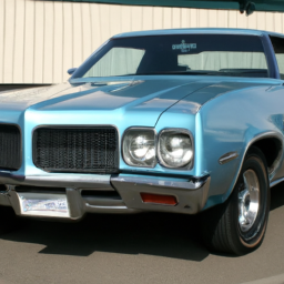
- 2023 Nissan Frontier SV Crew Cab POV Test Drive & Review Here we have a 2023 Nissan Frontier SV Crew Cab! This Frontier SV comes in deep blue pearl on charcoal cloth interior.
- 2023 Nissan Frontier – Intelligent Key Remote Battery Replacement
Below is a detailed guide on how to perform this replacement, including descriptions of each component involved in the process.
### Tools and Materials Needed
1. **Tools:**
– Socket set (including deep sockets)
– Wrench set
– torque wrench
– Ball joint separator or pickle fork
– Hammer
– Pry bar
– Pliers
– Screwdrivers
– Jack and Jack stands or a hydraulic lift
– Wheel chocks
– Safety glasses
– Gloves
2. **Materials:**
– New lower control arm
– New control arm bushings (if applicable)
– New ball joint (if not included with the control arm)
– New cotter pins (if applicable)
– Brake cleaner
– Grease (for new joints/bushings)
### Procedure
#### 1. Preparation
– **Safety First:** Ensure you are wearing safety glasses and gloves.
– **Park the Vehicle:** Park the Frontier on a flat, stable surface. Engage the parking brake and place wheel chocks behind the rear wheels.
– **Lift the Vehicle:** Use a hydraulic lift or Jack to raise the front end of the vehicle. Secure it with Jack stands to ensure it is stable before working underneath.
#### 2. Remove the Wheel
– Use a lug wrench to loosen and remove the lug nuts from the front wheel on the side you are replacing the lower control arm.
– Remove the wheel and set it aside.
#### 3. Disconnect the Brake Components
– **Brake Caliper:** Remove the caliper by unscrewing the caliper mounting bolts. Hang the caliper using a wire or bungee to avoid straining the brake line. Do NOT let it hang by the brake line.
– **Brake Rotor:** If necessary, remove the brake rotor by sliding it off the wheel hub.
#### 4. Disconnect the Suspension Components
– **Ball Joint:**
– Locate the ball joint connecting the lower control arm to the steering knuckle.
– Remove the cotter pin (if present) and loosen the nut on the ball joint.
– Use a ball joint separator or a pickle fork to separate the ball joint from the steering knuckle.
– **Stabilizer Bar Link (if applicable):** If the lower control arm is connected to a stabilizer bar, unbolt the link from the control arm.
– **Control arm Bolts:** Identify the bolts securing the lower control arm to the vehicle frame and the steering knuckle.
– Use the socket set to remove these bolts.
– Support the control arm with one hand while you remove the last bolt to prevent it from dropping.
#### 5. Remove the Lower Control Arm
– Once all connections are released, pull the lower control arm away from the vehicle. If it feels stuck, gently tap it with a hammer to free it from any remaining attachments.
#### 6. Install the New Lower Control Arm
– Align the new lower control arm with the mounting points.
– Insert the bolts to secure it to the vehicle frame and steering knuckle.
– Tighten the bolts to the manufacturer’s specified torque using a torque wrench.
#### 7. Reconnect the Suspension Components
– Reattach the ball joint to the steering knuckle and tighten the nut. Install a new cotter pin if applicable.
– Reconnect the stabilizer bar link (if applicable).
#### 8. Reinstall Brake Components
– Slide the brake rotor back onto the hub.
– Reattach the brake caliper and tighten the caliper mounting bolts.
#### 9. Reinstall the Wheel
– Place the wheel back onto the hub and hand-tighten the lug nuts.
– Lower the vehicle from the Jack stands and torque the lug nuts to the manufacturer’s specifications.
#### 10. Final Checks
– Before taking the vehicle for a test drive, double-check all connections and ensure everything is tight.
– Conduct a visual inspection to ensure no tools or parts are left under the vehicle.
### Conclusion
Replacing the lower control arm on a 2023 Nissan Frontier requires careful attention to detail and safety. If you are not comfortable or familiar with automotive repairs, it is advisable to consult a professional mechanic. Always refer to the vehicle’s service manual for specific torque specifications and any additional steps that may be needed for your particular model.
The throttle cable is a crucial component in the operation of internal combustion engines, specifically in vehicles equipped with a traditional mechanical throttle system. Its primary function is to connect the accelerator pedal to the throttle body, which regulates the amount of air entering the engine. When the driver presses the accelerator pedal, the throttle cable transmits this input to the throttle body, opening it to allow more air into the engine and thereby increasing power and speed.
Typically made of a flexible steel wire encased in a protective outer sheath, the throttle cable is designed to withstand tension and friction while ensuring smooth operation. The cable’s design allows for precise control over the throttle response, enabling the driver to modulate engine power effectively. In many modern vehicles, the throttle system has evolved with the incorporation of electronic throttle control (ETC), which replaces the mechanical linkage with sensors and electronic signals. However, throttle cables are still prevalent in older vehicles and some budget models.
Regular inspection and maintenance of the throttle cable are essential to ensure optimal performance. A frayed or damaged cable can lead to throttle sticking or failure, resulting in compromised engine performance or, in some cases, dangerous driving conditions. Overall, the throttle cable plays a vital role in the driving experience, linking driver input with engine response.

 handle batteries with care and dispose of the old battery properly.
 and replacement parts.
 and let it run for a few minutes.
 and allow it to cool down.
 and that there are no loose parts.
 and specifications tailored to your machine. If you’re not experienced with such repairs, consider consulting a professional mechanic.
 and torque specifications, as these can vary
 and the new
 and safety glasses to protect yourself while working.