Download Chrysler Town & Country 1998 1999 Workshop Service Manual –

service
Performing a CV (constant velocity) joint replacement on a Chrysler Town & Country is a detailed process that involves several steps. click here for more details on the download manual…..


    2011-2016 Chrysler Town & Country – Factory Radio Upgrade Options – Easy Plug & Play Inst… PRODUCT LINKS: 430 RBZ …

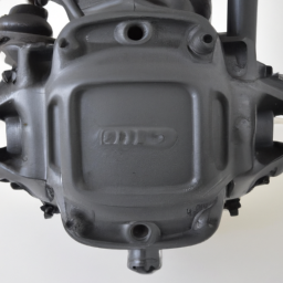
    Chrysler 62TE Transmission: Common Problems and Specs https://amzn.to/43i0HtT – All-in-One OBDII Car Scanner The Chrysler 62TE is a 6 speed automatic transmission. It was produced in …

Here is a reverse order explanation of the procedure:

### 8. **Reassemble Components**
– Reinstall any components that were removed or displaced during the process, such as the wheel, brake caliper, and rotor.
– Tighten the lug nuts in a crisscross pattern to ensure even pressure.

### 7. **Lower the Vehicle**
– Carefully lower the vehicle back to the ground using a jack.
– Remove the jack stands.

### 6. **Reattach the axle Shaft**
– Insert the new CV joint or axle shaft into the transmission or differential. Ensure that it’s securely seated.
– If applicable, reattach the retaining clip.

### 5. **Install the CV Joint**
slide the new CV joint onto the axle shaft, ensuring that it is properly aligned.
– Secure the joint with the appropriate retaining clips or bolts as needed.

### 4. **Remove the Old CV Joint**
Disconnect the axle shaft from the wheel hub by removing the axle nut and any other fasteners.
– Carefully slide the axle shaft out of the hub assembly.

### 3. **Disconnect Suspension Components**
– If necessary, Disconnect any suspension components that obstruct the removal of the axle, such as the lower control arm or tie rod end.
– Use appropriate tools to remove bolts and fasteners.

### 2. **Prepare the Vehicle**
– Park the vehicle on a level surface and engage the parking brake.
– Raise the front of the vehicle using a jack and secure it with jack stands.
– Remove the wheel on the side where the CV joint is being replaced.

### 1. **Gather Tools and Parts**
– Collect all necessary tools (like a socket set, wrenches, pry bar,download Chrysler Town Country workshop manual and a hammer) and the replacement CV joint/axle shaft.
– Ensure you have safety equipment, including gloves and goggles.

### Notes:
– Always consult the vehicle’s service manual for specific torque specifications and detailed instructions.
– If you are uncomfortable performing this repair, it is recommended to seek professional assistance.

This reverse outline provides a general framework for the CV joint replacement process. Each vehicle may have specific steps or additional components that need attention, so it’s important to refer to a detailed service manual for your specific model year.
A wiper blade is a crucial component of a vehicle’s windshield wiper system, designed to maintain visibility by clearing rain, snow, dirt, and other debris from the windshield. Typically made of a flexible rubber material, the blade is mounted on a metal or plastic frame that allows it to flex and conform to the curvature of the windshield. The wiper blade moves back and forth across the glass, powered by an electric motor or a mechanical linkage connected to the vehicle’s wiper switch.

Wiper blades come in various designs, including conventional blades, beam blades, and hybrid models. Conventional blades feature a simple structure with a metal frame, while beam blades have a more streamlined design that eliminates the need for a separate frame, providing better contact with the windshield and improved performance in adverse weather conditions. Hybrid models combine features from both types, offering the benefits of a beam design with the traditional wiper blade’s structure.

Regular maintenance and timely replacement of wiper blades are essential for optimal performance. Over time, the rubber can wear out, leading to streaking, skipping, or ineffective wiping. most experts recommend replacing wiper blades every six months to a year, depending on driving conditions and usage. In addition, the use of windshield washer fluid complements the wiper blades by helping to remove stubborn grime and ensuring clear visibility while driving. Overall, wiper blades play a vital role in ensuring safety and comfort during inclement weather, making them an indispensable feature of modern vehicles.

Download JCB 8013 Mini Excavator Workshop Service Repair Manual –

australia
Replacing the differential pinion bearing on a JCB 8013 Mini Excavator is a complex task that requires careful attention to detail and safety precautions. click here for more details on the download manual…..


    JCB JS220XD TRACKED EXCAVATOR C/W QUICK HITCH & BUCKET JCB JS220XD TRACKED EXCAVATOR C/W QUICK HITCH & BUCKET . 2 SPEED TRACKING . JOYSTICK CONTROLS . FULLY …

Below is a reverse order guide for the differential pinion bearing replacement process:

### 11. Reassemble the Differential Housing
– Reattach the differential cover, ensuring a proper seal with a new gasket or sealant as needed.
– Tighten the differential cover bolts to the manufacturer’s specifications.

### 10. Install the Drive Shaft
– Reconnect the drive shaft to the differential, ensuring it is properly aligned.
– Secure the drive shaft with the appropriate bolts and tighten them to specification.

### 9. Reinstall the Axles
– Carefully insert the axle shafts back into the differential housing.
– Make sure that the splines are properly engaged, and secure them with the retaining clips or bolts.

### 8. Reattach the Wheel Hubs
– Reinstall the wheel hubs and tighten the wheel nuts to the recommended torque specifications.
– Ensure that the brake components are reconnected if they were removed.

### 7. Refill Differential Oil
– Once the differential is reassembled, refill it with the appropriate type and amount of differential oil.
– Check for any leaks around the seals and gaskets.

### 6. Check Pinion Gear and Assembly
– Before final assembly, ensure that the pinion gear is correctly meshed with the ring gear.
rotate the pinion to check for any binding or irregularities.

### 5. Adjust Bearing Preload
– Use a torque wrench to adjust the pinion bearing preload according to manufacturer specifications.
rotate the pinion to ensure smooth operation and check for any play.

### 4. Remove Old Bearings
– Carefully remove the old pinion bearings from the pinion shaft and housing.
– Inspect the bearing races for wear and damage.

### 3. Install New Bearings
press new pinion bearings onto the pinion shaft and into the differential housing.
– Make sure they are properly seated and aligned.

### 2. Disassemble the Differential
– Remove the differential assembly from the housing, which may require disassembling various components.
– Take note of the order of assembly for reinstallation.

### 1. Prepare the Work Area
– Ensure you have all necessary tools, replacement parts (new bearings, seals, gaskets),download JCB 8013 Mini Excavator workshop manual and safety equipment.
– Disconnect the battery and secure the excavator on a flat surface.

### Important Notes:
– Always refer to the JCB 8013 Mini Excavator service manual for specific torque settings and detailed instructions.
– Ensure that you follow safety protocols, including wearing protective gear and working in a well-ventilated area.
– It may be helpful to take photos during disassembly to aid in reassembly.

This reverse order guide provides an overview of the steps involved in replacing the differential pinion bearing on a JCB 8013 Mini Excavator.
A rearview camera, also known as a backup camera, is an essential safety feature in modern vehicles that provides drivers with improved visibility and awareness when reversing. Positioned at the rear of the vehicle, typically near the license plate, the rearview camera captures real-time video footage of the area directly behind the vehicle. This imagery is transmitted to a display screen located inside the cabin, usually integrated into the dashboard or rearview mirror.

The primary purpose of the rearview camera is to enhance safety by reducing blind spots and helping drivers detect obstacles, pedestrians, or other vehicles that may be in their path while backing up. This technology is particularly beneficial in larger vehicles, such as SUVs and trucks, where rear visibility can be significantly limited. The camera often comes equipped with features like gridlines, which help drivers gauge distances and angles, making parking and maneuvering into tight spaces easier.

In addition to providing visual feedback, many rearview camera systems are now integrated with advanced safety features such as parking sensors and collision warning systems. These enhancements further assist drivers by alerting them to potential hazards as they reverse. As a result, rearview cameras have become a standard feature in many new vehicles, contributing to overall road safety and reducing the likelihood of accidents caused by reversing maneuvers.

Download Yanmar 4TNE98-HYF Industrial Diesel Engine Workshop Service Repair Manual – –

australian
Performing differential service on a Yanmar 4TNE98 HYF industrial engine involves checking and maintaining the differential, which is a critical component that allows the wheels to rotate at different speeds, especially when turning. click here for more details on the download manual…..

However, it’s important to clarify that the Yanmar 4TNE98 itself is an industrial engine typically found in various equipment, and “differential service” usually pertains to the vehicle or machine’s drivetrain rather than the engine itself.

Here’s a simplified guide on how to approach differential service:

### Tools and Materials Needed:
– Wrench set
– Socket set
– Screwdriver set
– Clean rags
– Differential oil (check the manual for specifications)
– Drain pan
– Funnel
– Safety glasses and gloves

### Steps for Differential Service:

1. **Safety First:**
– Ensure the machine is turned off, cool, and on a stable surface.
– Wear safety glasses and gloves to protect yourself.

2. **Locate the Differential:**
– The differential is usually located between the rear wheels of the vehicle or machine. It’s encased in a metal housing.

3. **Prepare for Draining:**
– Place a drain pan under the differential to catch the old oil.
– Locate the drain plug on the differential housing. This is typically a bolt or screw on the bottom of the housing.

4. **Drain the Old Oil:**
– Use a wrench or socket to carefully remove the drain plug.
– Allow the old oil to completely drain into the pan. This might take a few minutes.
– Once drained, clean the drain plug and inspect it for any metal shavings which could indicate wear.

5. **Replace the Drain Plug:**
– After all the oil has drained, replace the drain plug, ensuring it’s tightened securely but not over-tightened.

6. **Refill with New Oil:**
– Locate the fill plug on the differential, which is typically on the side or top of the housing.
– Remove the fill plug.
– Using a funnel, pour the new differential oil into the fill hole until it reaches the proper level. The level is usually just below the fill hole, but check your machine’s manual for the exact specifications.

7. **Check for Leaks:**
– After filling, replace the fill plug and tighten it securely.
check around the drain and fill plugs for any leaks.

8. **Clean Up:**
– Dispose of the old differential oil properly. Many auto parts stores will accept used oil for recycling.
– Clean any spillsdownload Yanmar 4TNE98 HYF Industrial Engine workshop manual and ensure that all tools are accounted for.

9. **Test the Machine:**
– Start the machine and allow it to run for a few minutes.
– Test the differential by driving the machine slowly and listening for any unusual noises.

### Additional Tips:
– Always refer to the owner’s manual for specific instructions and oil specifications for your machine.
– If you’re unsure about any step or if something doesn’t seem right, consult a professional mechanic.

By following these steps, you’ll be able to perform basic differential service, ensuring that your equipment runs smoothly and effectively.
A torque converter is a crucial component of an automatic transmission system in vehicles, designed to facilitate the transfer of power from the engine to the transmission. It serves as a fluid coupling between the engine and the transmission, allowing for smooth acceleration and deceleration without the need for a manual clutch. The primary function of the torque converter is to multiply engine torque during initial acceleration, enhancing the vehicle’s performance.

The torque converter consists of three main components: the impeller (or turbine), the turbine (or rotor), and the stator. The impeller is connected to the engine and spins with it, creating a flow of transmission fluid. This fluid is directed towards the turbine, which is linked to the transmission. As the turbine spins, it generates power to propel the vehicle forward. The stator, positioned between the impeller and turbine, redirects the fluid returning from the turbine back to the impeller, optimizing efficiency and preventing energy loss.

One of the key advantages of a torque converter is its ability to provide a seamless power transfer, enabling the vehicle to accelerate smoothly. Additionally, it allows for a certain degree of slip, which helps in preventing engine stalling when the vehicle is stationary. Overall, the torque converter plays an essential role in enhancing driving comfort and performance in automatic vehicles by bridging the gap between engine output and vehicle speed.

Download 1992 Mercedes-Benz G-Class G290GD (W460/W461) OEM Download Service & Repair Manual Software –

bookshop
Repairing the suspension crossmember on a Mercedes Benz G-Class G290GD (W460/W461) involves several steps. click here for more details on the download manual…..


    W202 mercedes kompresör tamiri için bize ulaşın

    Mercedes G-Class Three Lock Differentials Demonstration | Mercedes Lounge Mercedes G-Class Three Lock Differentials Demonstration. What is a three lock differential? This video was filmed at the G-Class …

Below is a reverse order guide to help you understand the process. Please note that this is a general overview and may require specific details depending on the condition of your vehicle and the extent of the damage.

### 7. Reinstallation and Final Checks
– **Reinstall Components**: Reattach any components you removed earlier, such as the exhaust system and any plastic covers.
– **Lower the Vehicle**: Carefully lower the vehicle back to the ground.
– **Torque Specifications**: Ensure all bolts and nuts are torqued to the manufacturer’s specifications.
– **Inspect for Leaks**: Check for any fluid leaks or abnormal sounds upon testing.

### 6. Finishing Touches
– **Clean Up**: clean the area around the crossmember and remove any tools or debris from the workspace.
– **Test Drive**: Take the vehicle for a short test drive to ensure everything is functioning correctly.

### 5. Welding and Painting
– **Weld the New Crossmember**: If a new crossmember has been installed, carefully weld it in place, ensuring that it is aligned correctly.
– **Paint for Protection**: Apply rust-resistant paint to any exposed metal to prevent corrosion.

### 4. Installation of New Crossmember
– **Position the Crossmember**: Place the new or repaired crossmember in position, ensuring it aligns with the frame and suspension components.
– **Secure the Crossmember**: Use bolts and washers to secure the crossmember to the vehicle’s frame.

### 3. Removal of Old Crossmember
– **Remove Fasteners**: Unbolt the old crossmember from the frame. This usually involves removing several bolts and possibly some brackets.
– **Detach Suspension Components**: Disconnect any suspension components that are attached to the crossmember, such as control arms or shock absorbers.

### 2. Preparation Before Repair
– **Safety Precautions**: Wear safety gear, including gloves and goggles. Ensure the vehicle is on a level surface and securely supported with jack stands.
– **Gather Tools and Parts**: Collect all necessary tools, including wrenches, sockets, and possibly a cutting tool if the old crossmember needs to be cut out. Have the replacement crossmemberdownload Mercedes Benz G Class G290GD W460 W461 OEM workshop manual and any other parts ready.

### 1. Initial Diagnosis and Assessment
– **Inspect the Crossmember**: Start by carefully inspecting the crossmember for damage, rust, or any other issues that may require repair or replacement.
– **Decide on Repair vs. Replacement**: Determine whether the crossmember can be repaired or if it needs to be replaced entirely.

### Important Notes:
– **Consult Repair Manuals**: Refer to the vehicle’s service manual for specific torque specifications and any special instructions pertaining to your model.
– **Professional Help**: If unsure about any step, consider seeking help from a professional mechanic, especially for welding and structural repairs.

This reverse order guide should help you understand the process of repairing or replacing the suspension crossmember on a Mercedes Benz G-Class G290GD. Always prioritize safety and accuracy in every step.
The cigarette lighter, often referred to as a power outlet or accessory socket in modern vehicles, is a component originally designed for igniting cigarettes. It consists of a cylindrical metal socket that connects to the vehicle’s electrical system. When the lighter is pressed in, an internal heating element is activated, causing it to heat up to a red-hot temperature. This feature allowed users to light a cigarette by removing the heated lighter from its socket and using it to ignite tobacco.

Over time, the function of the cigarette lighter has evolved significantly. While it still retains its original purpose, many cars now include it as a 12-volt power outlet, enabling users to power various electronic devices. This is particularly useful for charging smartphones, powering GPS devices, and operating other accessories like dash cams or portable air compressors. The socket typically uses a standardized design, making it compatible with a wide range of adaptors and chargers.

Despite its name, the cigarette lighter is seldom used for smoking purposes today, as health awareness and regulations around tobacco use have increased. Nevertheless, it remains a staple in vehicle design, reflecting the broader trend of integrating convenience and technology into automotive interiors. Its functionality and ease of use make it an essential component for modern drivers, offering a practical solution for maintaining connectivity on the go.

Download 2000 Mercedes-Benz C-Class 200 (W202) OEM Service & Repair Manual Software –

repairs
Shifting drum repair on a Mercedes Benz C Class 200 W202 involves several steps and requires specific tools and materials. click here for more details on the download manual…..


    W202 mercedes kompresör tamiri için bize ulaşın

    Mercedes W202 C Klasse Benziner in Betrieb. Fahrt W202 C180 durch den Frühling.

Below is a detailed guide to help you through the process:

– **Tools Required:**
– **Socket Set:** A complete metric socket set (including 10mm, 13mm, and 17mm sockets) will help in removing bolts and nuts.
– **Torque Wrench:** Ensures that bolts are tightened to the manufacturer’s specifications.
– **Screwdrivers:** A flathead and Phillips screwdriver for various screws and clips.
– **Pliers:** Needle-nose pliers are useful for manipulating small parts and clips.
– **Brake Tool:** If you have drum brakes, a brake tool might be necessary for adjusting the brake shoes.
– **Hammer:** A rubber mallet can assist in loosening stubborn parts without causing damage.
– **Pry Bar:** Useful for removing the drum if it’s stuck.
– **Jack and Jack Stands:** For safely lifting and supporting the vehicle.
– **Brake Cleaner:** To clean components as needed.
– **Shop Towels:** For wiping down parts and cleaning up.
– **Replacement Parts:** Ensure you have the correct OEM parts for the shifting drum and any associated hardware.

– **Safety Precautions:**
– **Wear Safety Gear:** always wear safety glasses and gloves to protect against debris and sharp edges.
– **Ensure Stability:** Make sure the vehicle is on a flat surface and securely supported by jack stands before starting any work.

– **Preparation:**
– **Disconnect the Battery:** To prevent any electrical issues, disconnect the negative terminal of the battery.
– **Remove the Wheel:** Use a jack to lift the vehicle and remove the wheel to access the brake assembly.

– **Accessing the Drum:**
– **Remove the Brake Drum:** If applicable, unbolt and slide off the brake drum. If it’s stuck, gently tap it with a rubber mallet.
– **Inspect Components:** Check the brake shoes, springs, and other components for wear or damage.

– **Removing the Shifting Drum:**
– **Locate the Shifting Drum:** Identify the shifting drum, which is typically located near the rear axle.
– **Unbolt the Drum:** Use the appropriate socket size to remove the bolts securing the shifting drum.
– **Disconnect Linkages:** Carefully detach any linkages or cables connected to the drum, taking note of their positions for reinstallation.

– **Replacing or Repairing the Drum:**
– **Inspect the Drum:** Check for wear or damage. If it’s severely worn, replace it with an OEM part.
– **Clean the Area:** Use brake cleaner to remove any debris or contaminants from the area.
– **Install New Drum:** If replacing, position the new shifting drum and secure it with bolts. Ensure it aligns correctly with the other components.

– **Reassembly:**
– **Reconnect Linkages:** Reattach any linkages or cables you previously disconnected, ensuring they are secured properly.
– **Reinstall Brake Drum:** If applicable, reinstall the brake drum, ensuring it spins freely without obstruction.
– **Reattach Wheel:** Mount the wheel back ondownload Mercedes Benz C Class 200 W202 OEM workshop manual and hand-tighten the lug nuts.

– **Final Steps:**
– **Lower Vehicle:** Carefully lower the vehicle back to the ground and remove the jack stands.
– **Reconnect Battery:** Reconnect the negative terminal of the battery.
– **Test Operation:** Before driving, test the operation of the shifting drum by engaging the transmission and ensuring smooth operation.

– **Torque Specifications:**
– **Follow OEM Specs:** Use the torque wrench to tighten all bolts to the manufacturer’s specifications, typically found in the vehicle’s service manual.

– **Road Test:**
– **Check Functionality:** After repairs, take the vehicle for a short test drive to ensure everything operates smoothly.

By following these steps with the appropriate tools and precautions, you should be able to successfully repair or replace the shifting drum on your Mercedes Benz C Class 200 W202. always refer to the vehicle’s service manual for specific details related to your model.
The connecting rod is a crucial component in internal combustion engines, serving as a key link between the piston and the crankshaft. Its primary function is to convert the linear motion of the piston, which is driven by the combustion of fuel and air, into the rotational motion required to turn the crankshaft. This transformation of motion is essential for the engine’s overall operation and power delivery to the vehicle’s drivetrain.

Typically constructed from high-strength materials such as forged steel or aluminum alloys, connecting rods must withstand significant stress and tension during the engine’s operation. They are designed to be lightweight yet robust, ensuring minimal energy loss while providing the necessary strength to handle high temperatures and pressures generated within the engine.

Connecting rods come in various designs, including I-beam and H-beam configurations, each offering different benefits in terms of weight, strength, and performance. The ends of the connecting rod feature bearings: one end connects to the piston via a wrist pin, while the other end connects to the crankshaft. Proper alignment and clearance are critical to prevent excessive wear and ensure smooth operation.

Additionally, modern advancements in manufacturing techniques have led to the development of connecting rods that are optimized for performance and efficiency, often incorporating features such as oil passages for lubrication and cooling. Overall, the connecting rod plays a vital role in the functionality and efficiency of an engine, contributing significantly to the vehicle’s performance and reliability.

Download Jeep CJ-3A 1949-1953 Workshop Service Manual –

fix
Replacing a CV joint on a Jeep CJ-3A involves several steps to ensure that you perform the repair safely and effectively. click here for more details on the download manual…..


    1949 CJ-3A – L134 – Flathead – Freeze / Core Plug Replacement & Cooling System Flush Welcome back to channel! In today’s video, I cover replacing a common freeze plug on the L134 flathead in this ’49 CJ-3A. *If you …

    Comparison of Jeep CJ3A & M38 Walk-Around and Comparison of CJ3A & M38 Jeep Willy’s with ​⁠@therealjeepguy #jeep #thejeepguy #offroad #willysjeep …

The CV (constant velocity) joint is a crucial component that allows the drive shaft to transmit power to the wheels while accommodating the up-and-down motion of the suspension and allowing for steering. Here’s a detailed guide on how to perform a CV joint replacement:

### Tools and Materials Needed:

1. **Tools:**
– Socket set (including deep sockets)
– Wrench set
– Torque wrench
– Pliers
– Screwdrivers (flathead and Phillips)
– Hammer
– Pry bar
– Jack and jack stands
– CV joint puller (if necessary)

2. **Materials:**
– Replacement CV joint or axle assembly
– New CV joint grease (if applicable)
– New axle nut (if applicable)
– New cotter pins (if applicable)
– Brake cleaner
shop rags or paper towels

### Step-by-Step Guide:

#### 1. Preparation:
– **Safety First:** Park the Jeep on a flat surface, engage the parking brake, and place wheel chocks behind the rear wheels.
– **Gather Tools and Materials:** Ensure you have all the necessary tools and replacement parts before starting.

#### 2. Lift the Jeep:
– Use a jack to lift the front of the Jeep CJ-3A and secure it on jack stands. Make sure it’s stable before proceeding.

#### 3. Remove the Wheel:
– **Loosen Lug Nuts:** Using a socket wrench, slightly loosen the lug nuts on the front wheel where you are replacing the CV joint.
– **Remove Wheel:** Completely remove the lug nuts and take off the wheel.

#### 4. Remove the Brake Caliper (if applicable):
– Depending on your Jeep’s setup, you might need to remove the brake caliper to access the CV joint. If so:
– Remove the bolts holding the caliper in place.
– Carefully hang the caliper using Wire or a bungee cord to prevent stress on the brake line. Do not let it hang by the brake line.

#### 5. Remove the Axle Nut:
– **Access the Axle Nut:** If there’s a dust cover, remove it to access the axle nut.
– **Remove the Nut:** Use a socket wrench to remove the axle nut. If it’s stubborn, a breaker bar may be necessary.

#### 6. Detach the CV Joint from the Wheel Hub:
– **Pry Out the CV Joint:** Use a pry bar to carefully separate the CV joint from the wheel hub. Be cautious not to damage any surrounding components.
– If the joint is stuck, you may need to tap it gently with a hammer, But be careful to avoid damaging the threads or the hub.

#### 7. Remove the CV Joint from the Differential:
– **Access the CV Joint:** If the CV joint connects to the differential, you will need to pull it out.
– **Pull the Joint Out:** Gently pull the CV axle out of the differential. You may need to rotate the axle slightly to ease the removal.

#### 8. compare Old and New CV Joint:
– Before installation, compare the old CV joint with the new one to ensure they are the same size and fit.

#### 9. Install the New CV Joint:
– **Insert the New Joint:** Slide the new CV joint into the differential first. Ensure it is seated properly.
– **Reattach to Wheel Hub:** Align the CV joint with the wheel hub and push it into place. You may need to rotate it slightly to get it fully seated.

#### 10. Replace the Axle Nut:
– Once the CV joint is in place, thread on the new axle nut. Make sure it’s download Jeep CJ 3A workshop manualhand-tightened first.

#### 11. Reinstall the Brake Caliper (if removed):
– Reattach the brake caliper and tighten the bolts securely.

#### 12. Replace the Wheel:
– **Reattach the Wheel:** place the wheel back on and hand-tighten the lug nuts.
lower the Jeep back to the ground.

#### 13. Tighten the Axle Nut and Lug Nuts:
– **Torque the Axle Nut:** Use a torque wrench to tighten the axle nut to the manufacturer’s specifications.
– **Torque the Lug Nuts:** Tighten the lug nuts in a crisscross pattern to ensure even pressure.

#### 14. Test the Repair:
– Before taking the Jeep for a drive, check that everything is secure and properly installed. Test drive the vehicle at low speed to listen for any unusual noises.

### Final Thoughts:
Replacing a CV joint can be a challenging task, especially for those unfamiliar with automotive repairs. If you’re unsure or uncomfortable with any step, consider consulting a professional mechanic. Always refer to the Jeep CJ-3A’s repair manual for specific torque specifications and detailed diagrams for your particular model.
An odometer is a vital instrument found in vehicles that measures the distance traveled by the vehicle over its lifespan. It is an essential component for both drivers and automotive professionals, as it provides crucial information regarding the vehicle’s usage and helps in assessing its overall condition. Traditionally, odometers were mechanical devices consisting of a series of gears and rotating drums that displayed the mileage on a physical dial. However, modern vehicles typically use electronic odometers, which display the distance digitally on the dashboard.

Odometers serve several important functions. For one, they help vehicle owners monitor maintenance schedules; many maintenance tasks are recommended based on mileage, such as oil changes, tire rotations, and other critical services. Furthermore, the odometer reading is a key factor in determining the vehicle’s resale value. A car with lower mileage is often perceived as being in better condition and may command a higher price in the used car market.

In addition to standard distance measurement, some odometers also include trip settings that allow drivers to track the distance of specific journeys separately from the total mileage. This feature can be useful for calculating fuel efficiency or for business purposes, where mileage tracking is essential for expense reimbursement.

Lastly, it is important to note that tampering with odometers, a practice known as “odometer rollback,” is illegal in many jurisdictions, as it misrepresents the vehicle’s true usage and can lead to significant financial and safety implications for future buyers. Overall, the odometer is a fundamental component that plays a crucial role in vehicle maintenance, valuation, and safety.

Download MAZDA 3Service & Repair Manual 2003-2006 –

stores
Repairing power steering on a Mazda 3 can be a bit complex, but I’ll break it down into simpler steps. click here for more details on the download manual…..


    2024 Mazda3 vs Mazda CX-30 / Open and Shut? On the surface, the CX-30 is a more versatile, AWD Mazda3 without a real price increase. After driving them back to back, the …

    How to fix heat issue on Mazda 3 (2015) Quick video of one method that fixes the heating issues on the Mazda 3.

Keep in mind that if you’re not comfortable working on vehicles, it’s always a good idea to seek help from a professional mechanic. Here’s a general guide to understanding and potentially addressing power steering issues on a Mazda 3:

### What You Need:
1. **Basic Tools**: Wrenches, screwdrivers, pliers, and possibly a ratchet set.
2. **Power Steering Fluid**: Make sure you have the correct type for your Mazda 3.
3. **Rags or Towels**: For cleaning up any spills.
4. **Safety Gear**: Gloves and safety glasses.

### Symptoms of power Steering Issues:
– Difficulty steering the car.
– A whining noise when turning the steering wheel.
– Fluid leaks under the car.
– Steering wheel feels stiff or unresponsive.

### Steps to Address power Steering Issues:

#### 1. **Check the power Steering Fluid Level**:
– Locate the power steering reservoir. This is usually near the engine and has a cap labeled for power steering.
– Check the fluid level against the markings on the reservoir.
– If it’s low, add the correct type of power steering fluid until it reaches the recommended level.

#### 2. **Inspect for Leaks**:
– Look under the car and around the power steering components for any signs of fluid leaks.
– Common leak spots include the power steering pump, hoses, and the steering rack.
– If you find a leak, you may need to replace the affected part (pump, hose, or rack).

#### 3. **Examine the power Steering Belt**:
– Locate the belt that connects to the power steering pump. It should be tight and in good condition.
– If the belt is loose, worn, or cracked, it may need to be tightened or replaced.

#### 4. **Check the power Steering Pump**:
– If you’re still having issues after checking fluid and the belt, the power steering pump may be faulty.
– Listen for unusual noises coming from the pump when the engine is running.
– If the pump is noisy or not functioning properly, it may need to be replaced. This usually requires more mechanical skill.

#### 5. **Bleed the power Steering System**:
– If you’ve added fluid, you may need to bleed the system to remove air bubbles.
– Turn the steering wheel from lock to lock several times while the engine is running. This helps circulate the fluiddownload MAZDA 3 workshop manual and push out any air.

#### 6. **Test Drive the Vehicle**:
– After making any adjustments or repairs, take the car for a short drive to see if the steering feels normal.
– Check again for any leaks or unusual sounds.

### Important Notes:
– **Safety First**: Always ensure the car is parked on a flat surface, and the engine is off before starting any work.
– **Consult the Owner’s Manual**: Your Mazda 3’s owner manual can provide specific information about fluid types and other details unique to your vehicle.
– **Seek Help if Needed**: If you’re uncertain or if the problem persists, it’s best to consult a professional mechanic.

Remember, regular maintenance can help prevent power steering issues from occurring in the first place!
The fuel pump is a critical component of an internal combustion engine’s fuel delivery system. Its primary function is to transport fuel from the fuel tank to the engine, ensuring that the engine receives the appropriate amount of fuel for efficient combustion. Fuel pumps can be categorized into two main types: mechanical and electrical.

Mechanical fuel pumps are commonly found in older vehicles and rely on the engine’s vacuum to draw fuel from the tank. They are typically mounted on the engine and use a diaphragm mechanism to pump fuel. In contrast, modern vehicles predominantly utilize electric fuel pumps, which are submerged in the fuel tank. These pumps use an electric motor to create the necessary pressure to push fuel through the system.

An electric fuel pump offers several advantages, including more efficient fuel delivery and the ability to maintain a consistent pressure, which is crucial for optimal engine performance. The fuel pump works in conjunction with various sensors and the engine control unit (ECU) to adjust the flow rate based on the engine’s demands, such as during acceleration or idling.

Fuel pumps are designed to withstand harsh conditions, including exposure to heat and vibration. A failing fuel pump can lead to a range of issues, including poor engine performance, stalling, or even complete engine failure, making regular maintenance and timely replacement important for vehicle reliability. Thus, the fuel pump plays an essential role in the overall performance and efficiency of an automobile.

Download Kobelco E235SR Operators Manual –

sale
Repairing a turbocharger on a Kobelco E235SR excavator can be a complex task, but I’ll break it down into simpler steps. click here for more details on the download manual…..


    2004 KOBELCO SK235SR LC-1E For Sale http://www.machinerytrader.com/listingsdetail/detail.aspx?OHID=27676039 Title: 2004 KOBELCO SK235SR LC-1E For Sale …

    FC2098 – SCANIA G450 XT – 2019 Tracteur Routier SCANIA G450 XT – 2019 1ère M.E.C. : 10/2019 Boîte automatique 1 couchette Norme Euro 6 186 353 km …

First, please remember that if you’re not comfortable with mechanical work, it’s best to consult a professional. Here’s a simplified guide on how to approach turbocharger repair:

### Tools and Materials You Might Need:
– Basic hand tools (wrenches, sockets, screwdrivers)
– Torque wrench
– Gasket scraper or razor blade
– Replacement gaskets and seals
– Engine oil
– Cleaning rags
– Safety gear (gloves, goggles)

### Safety First:
1. **Turn Off the Engine**: Ensure the engine is completely off and cool.
2. **Disconnect the Battery**: This prevents any electrical issues or accidental starts.
3. **Wear Safety Gear**: Gloves and goggles protect you from dirt and sharp objects.

### Step-by-Step Process:

#### 1. **Locate the Turbocharger**:
– The turbocharger is usually mounted on the engine. Look for a round, metallic component connected to the engine with pipes leading to and from it.

#### 2. **Remove the Turbocharger**:
– **Disconnect Pipes**: Carefully disconnect the intake and exhaust pipes. Use a wrench to loosen the bolts or clamps.
– **Remove the Turbo**: Once the pipes are off, there may be bolts holding the turbocharger to the engine. Use the appropriate socket to remove these bolts.

#### 3. **Inspect the Turbocharger**:
– Look for visible signs of damage like cracks or excessive wear. Check the turbine blades for any chips or bends.
– If the turbocharger is excessively worn or damaged, it may need to be replaced entirely.

#### 4. **Clean the Turbocharger**:
– If it’s dirty, clean the exterior and the inlet/outlet ports with a rag. Use a gasket scraper to remove old gasket material from the mounting surfaces.

#### 5. **Replace Gaskets and Seals**:
– Install new gaskets and seals to ensure there are no leaks when you reassemble everything. Make sure they fit snugly.

#### 6. **Reinstall the Turbocharger**:
– Position the turbocharger back onto the engine. Secure it with the bolts you removed earlier, ensuring they are tightened to the manufacturer’s specifications (use a torque wrench if you have one).

#### 7. **Reconnect Pipes**:
– Reattach the intake and exhaust pipes, ensuring they are securely fastened.

#### 8. **Reconnect the Battery**:
– Once everything is reassembled, reconnect the battery.

#### 9. **Start the Engine**:
– Start the engine and listen for any unusual noises. Check for leaks around the turbocharger.

#### 10. **Final Checks**:
– After a short run, turn off the engine and check if everything is secure and there are no leaks.

### Important Tips:
– **Take Photos**: If you’re unsure about how things go back together, take photos during disassembly to reference later.
– **Consult the Manual**: If you have the operator’s manual for the Kobelco E235SR, it can provide specific torque settingsdownload Kobelco E235SR s workshop manual and additional guidance.
– **Don’t Rush**: Take your time to ensure everything is done correctly.

### When to Seek Help:
If you encounter any issues that seem beyond your skill level or if the turbocharger is severely damaged, consider consulting a professional mechanic. Turbochargers are vital components, and improper repair can lead to further engine damage.

By following these steps and tips, you should have a clearer understanding of how to approach turbocharger repair on a Kobelco E235SR excavator. Always prioritize safety and make sure you’re comfortable with each step before proceeding.
The cigarette lighter, also known as the auxiliary power outlet or 12V socket, is a component found in many vehicles that serves as both a functional and symbolic accessory. Originally designed to heat tobacco for smoking, the cigarette lighter has evolved into a versatile power source for various electronic devices. Typically located on the dashboard or in the center console, it consists of a cylindrical socket that can accommodate a removable metal lighter element.

When the lighter is activated, an electrical current heats a coiled wire element until it glows red hot, allowing users to ignite cigarettes or other smoking materials. However, as smoking rates have declined and health awareness has increased, the usage of the cigarette lighter has shifted significantly. Today, it is more commonly used to power portable devices such as smartphones, GPS units, dash cams, and other electronic accessories through specialized adapters.

The cigarette lighter socket operates on a standard 12-volt electrical system, making it compatible with a wide range of devices. Many modern vehicles come equipped with multiple outlets to accommodate the growing number of electronic gadgets that drivers and passengers use. Despite its name, the cigarette lighter has become a multifunctional component, representing the intersection of automotive design and the increasing reliance on technology in everyday life. Its enduring presence in vehicles highlights its practicality and adaptability in an ever-evolving automotive landscape.

Download Liebherr R 996 Hydraulic Excavator Complete Workshop Service Repair Manual –

bookstore
Repairing the suspension arm on a Liebherr R 996 Hydraulic Excavator is a complex task that requires a detailed understanding of the machine’s mechanical systems and appropriate safety measures. click here for more details on the download manual…..


    Hydraulic RC Excavator. The first tests 3

    Oil in Coolant Reservoir? 6 Causes & How To Fix It

Below is a comprehensive guide outlining the necessary tools and steps for a successful suspension arm repair.

### Tools Needed

– **Wrenches and Sockets**
– A set of metric wrenches and sockets to fit various bolt sizes on the suspension arm.
– Ratchet and extension bars for better access to tight spaces.

– **Torque Wrench**
– Essential for applying the correct torque specifications when reassembling components to prevent over-tightening or under-tightening.

– **Hammer**
– A heavy-duty hammer (e.g., sledgehammer) for driving out stubborn pins and bushings.

– **Pry Bar**
– A sturdy pry bar to help leverage and separate components when disassembling the suspension arm.

– **Hydraulic Jack**
– A hydraulic jack or a jack stand to lift the excavator safely and support it during the repair process.

– **Creeper or Mechanic’s Stool**
– To comfortably work underneath the excavator, providing mobility and access to the suspension components.

– **Cutting Tools**
– Angle grinder or reciprocating saw to cut through any damaged or rusted components that cannot be removed otherwise.

– **Pneumatic Tools (Optional)**
– Air impact wrench for quicker removal of bolts and nuts, especially those that are rusted or seized.

– **Bearing Puller**
– For extracting bearings and bushings from the suspension arm assembly without causing damage.

– **Cleaning Supplies**
– Degreaser, rags, and brushes to clean the suspension arm and surrounding areas before inspection and repair.

– **Lubrication Tools**
– Grease gun and appropriate lubricant for reassembling components to ensure smooth operation.

– **Replacement Parts**
– New suspension arm bushings, pins, and any other necessary components based on inspection findings.

### Steps for Suspension Arm Repair

– **Safety Precautions**
– Ensure the excavator is parked on a flat surface and engage the parking brake.
– Use proper personal protective equipment (PPE) such as gloves, safety glasses, and steel-toed boots.

– **Prepare Work Area**
– Clear the surrounding area of any obstacles and ensure there is adequate lighting for the repair work.

– **Lift the Excavator**
– Use the hydraulic jack to lift the excavator, placing jack stands securely beneath the frame for safety.

– **Remove the Wheel/Track (if necessary)**
– Depending on the configuration, remove the wheel or track assembly to gain access to the suspension arm.

– **Disassemble the Suspension Arm**
– Start by removing any protective covers or guards.
– Use the appropriate wrenches and sockets to detach the bolts securing the suspension arm to the chassis and other components.
– Carefully drive out any pins or bushings using a hammer and bearing puller, if needed.

– **Inspect Components**
– Thoroughly inspect the suspension arm for signs of wear, cracks, or damage.
– Check bushings, pins,download Liebherr R 996 Hydraulic Excavator workshop manual and mounting points for any defects that need addressing.

– **Clean the Area**
– Use degreaser and rags to clean the suspension arm and surrounding components to remove dirt and debris.

– **Replace Damaged Parts**
– Install new bushings and pins as required. Ensure that all components meet manufacturer specifications.
– If any structural repairs are needed, weld or replace sections of the suspension arm as necessary.

– **Reassemble the Suspension Arm**
– Position the suspension arm back in place and secure it with bolts, ensuring to apply the correct torque using the torque wrench.
– Reinstall any protective covers or guards that were removed.

– **Lubricate Moving Parts**
– Use a grease gun to lubricate all moving parts, ensuring smooth operation.

– **Test Functionality**
– Once reassembled, carefully lower the excavator and conduct a visual inspection.
– Test the suspension arm by operating the excavator at low speeds to ensure proper function and stability.

– **Final Inspection**
– After testing, conduct a final inspection to confirm that all components are secure and functioning as intended.

– **Document the Repair**
– Record all repairs made, including parts replaced and any observations for future reference.

By following these detailed steps and utilizing the appropriate tools, you can effectively repair the suspension arm on a Liebherr R 996 Hydraulic Excavator, ensuring optimal performance and safety during operation.
A tow strap, also known as a towing strap or recovery strap, is a specialized piece of equipment designed for safely pulling or towing vehicles that are immobilized due to various reasons, such as mechanical failure or getting stuck in mud or snow. Typically made from durable materials like nylon or polyester, tow straps are engineered to withstand significant tension and force, allowing them to handle the weight of the vehicle being towed.

Tow straps usually feature reinforced loops or hooks on both ends, which facilitate secure attachment to the towing vehicle and the vehicle being towed. This design ensures that the strap can be easily connected and disconnected while providing a reliable grip during towing operations. The straps come in various lengths and widths, with the strength rated in terms of pulling capacity, often measured in pounds or tons. It is crucial to select a tow strap that exceeds the weight of the vehicle being towed to ensure safety and prevent breakage.

In addition to their primary function of towing, tow straps can also be used in off-road recovery situations, where vehicles may become stuck in challenging terrain. Safety is paramount when using a tow strap; users should always follow proper techniques and guidelines to avoid accidents or injuries. Overall, a tow strap is an essential accessory for vehicle owners, especially those who frequently engage in outdoor activities or travel in areas where breakdowns may occur.

Download MITSUBISHI D04FD, D04FD-TAA Diesel Engine Service Repair Manual – ! –

owners manual
Air suspension repairs on a Mitsubishi D04FD engine involve a series of steps and the use of specific tools. click here for more details on the download manual…..


    R145LC-9 Hyundai Excavator Engine Overhaul Rebuild Kit for Mitsubishi Engine D04FD-TAA R145LC-9 Hyundai Excavator Engine Overhaul Rebuild Kit for Mitsubishi Engine D04FD-TAA From www.soonparts.com Online …

    2012 Hyundai Robex 140LC-9 excavator for sale | sold at auction October 8, 2015 SOLD! Construction Equipment Auction This asset was for sale and sold for a contract price of $48400 in an absolute, no-reserve …

Here’s a detailed breakdown of the process and the tools required:

### Tools Required

– **Air Suspension Repair Kit**
– Contains air springs, fittings, and necessary hardware specific to the D04FD model.

– **Socket Set**
– A comprehensive socket set (including both metric and standard sizes) will help you remove and reinstall bolts and nuts efficiently.

– **Wrench Set**
– A set of combination wrenches for tightening and loosening various components, particularly for hard-to-reach areas.

– **Torque Wrench**
– Essential for tightening bolts to the manufacturer’s specified torque settings, ensuring safety and performance.

– **Pliers**
– Needle-nose and standard pliers will be useful for manipulating small components and securing clamps or connectors.

– **Flathead and Phillips Screwdrivers**
– For removing any screws that hold covers or components in place.

– **Air Compressor**
– To test the air suspension system after repairs, ensuring it holds air properly.

– **Diagnostic Tool**
– A device that can read fault codes from the vehicle’s onboard computer, helping to identify issues in the air suspension system.

– **Safety Gear**
– Gloves, goggles, and a mechanic’s apron to protect yourself during the repair process.

### Repair Process

– **Diagnosis**
– Use the diagnostic tool to check for any error codes related to the air suspension system. This will help identify specific issues that need addressing.

– **Safety Precautions**
– Ensure the vehicle is parked on a flat surface. Engage the parking brake and use wheel chocks to prevent movement. Disconnect the battery to avoid electrical issues during the repair.

– **Inspect Air Suspension Components**
– Examine the air springs, compressors, and air lines for any visible signs of wear, damage, or leaks. Look for cracks, tears, or corrosion.

– **Remove Old Air Springs**
– Use the socket set and wrenches to remove the bolts securing the air springs in place. Carefully detach any air lines connected to the springs, ensuring you do not damage the fittings.

– **Install New Air Springs**
– Position the new air springs in place. Reconnect the air lines, ensuring a secure and leak-free connection. Use the torque wrench to tighten bolts to the manufacturer’s specifications.

– **Replace Air Compressor (if necessary)**
– If diagnostics indicate a faulty compressor, remove it using the socket set. Install the new compressor, ensuring proper alignment and connections.

– **Reconnect Electrical Connections**
– Ensure all electrical connections are secure, including any sensors that may be part of the air suspension system.

– **Recheck All Connections**
– Double-check that all fittings, hoses,download MITSUBISHI D04FD D04FD TAA Engine workshop manual and bolts are tightened appropriately and that there are no obstructions.

– **Reconnect Battery**
– Once all components are in place, reconnect the battery and clear any diagnostic codes from the system.

– **Test the System**
– Start the vehicle and allow it to run for a few minutes to let the air suspension system activate. Use the air compressor to inflate the air springs and check for any leaks or irregularities.

– **Final Inspection**
– Conduct a final inspection of the air suspension system while the vehicle is running. Look for any signs of air leaks or improper function.

– **Road Test**
– Take the vehicle for a short drive to ensure the air suspension is functioning correctly and providing a smooth ride.

### Conclusion

Performing air suspension repairs on a Mitsubishi D04FD engine requires careful attention to detail and the right tools. Following these steps will help ensure that the air suspension system is properly repaired and restored to optimal functionality. Always refer to the vehicle’s service manual for specific instructions and torque specifications.
An airbag is a crucial safety feature in modern vehicles, designed to protect occupants during a collision by providing a cushion that mitigates the impact forces. Typically made from nylon or polyester, an airbag is a flexible fabric sac that inflates rapidly in the event of an accident, usually deploying in milliseconds. The deployment of an airbag is triggered by sensors that detect sudden deceleration or impact, signaling the airbag control unit to release gas from a canister, which fills the airbag and allows it to expand.

Airbags are strategically positioned throughout a vehicle, including the steering wheel, dashboard, side panels, and even the roof, to provide comprehensive coverage for passengers. There are various types of airbags, including front airbags that protect the driver and front passenger, side airbags that shield occupants from lateral impacts, and curtain airbags that deploy from the roof to protect against side collisions.

While airbags significantly enhance passenger safety, they are most effective when used in conjunction with seat belts. It’s important to note that airbags are designed to work in high-impact scenarios, and their deployment can sometimes cause minor injuries, such as abrasions or bruises, due to the force of inflation. Overall, airbags have been instrumental in reducing fatalities and serious injuries in vehicle accidents, making them an essential component of automotive safety systems.